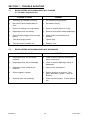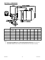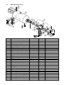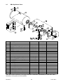
1
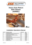
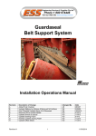
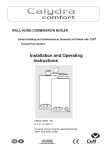
BIG BLASTER AIR CANNON SAFE WORKING PROCEDURES (SWP) INSTALLATION MANUAL Revision A B C D E F Revision F Description of Change Added Final Checklist Changed to Metric Tanks Updated Melbourne Address & Removed SA Address Commisioning Section (5) added to manual (CR 2608) Final Checklist Updated Items 4 & 5 Reversed Section 9 item 1 BB2-50 should be BB2-15 1 Changed By AS TT SH SH SH KOR Date 28/5/07 15/12/08 3/08/09 14/08/09 15/04/10 24-01-2011 24-01-2011 ENGINEERING SERVICES and SUPPLIES OFFICE DETAILS ESS HEAD OFFICE 11-13 TRADERS WAY PO BOX 121 CURRUMBIN QLD 4223 P: (07) 5589 2000 F: (07) 5598 1353 ESS MACKAY 1 PROGRESS STREET PO BOX 5755 MACKAY MC QLD 4740 P: (07) 4952 4600 F: (07) 4952 4717 ESS PERTH 19 CLAVERING ROAD BAYSWATER WA 6053 P: (08) 9370 3155 F: (08) 9272 5130 ESS MAITLAND UNIT 2 BARTON COURT 6 JOHNSON STREET MAITLAND NSW 2320 P: (02) 4932 3544 F: (02) 4932 3611 ESS WOLLONGONG 1/20 DOYLE AVENUE PO BOX 343 UNANDERRA NSW 2526 P: (02) 4272 4422 F: (02) 4272 4434 ESS MELBOURNE 4/314 Governor Road BRAESIDE VIC 3195 P: (03) 9580 0388 F: (03) 9587 5199 ESS EMERALD 11/115 ROBERTS STREET EMERALD QLD 4720 P: (07) 4982 4855 F: (07) 4987 5118 ESS GLADSTONE 2/34 CHAPPLE STREET PO BOX 1475 GLADSTONE QLD 4680 P: (07) 4972 3759 F: (07) 4972 2866 ESS ADELAIDE P: (08) 8262 8955 F:(08) 8262 4944 ESS KALGOORLIE 4/235 HAY STREET PO BOX 10471 KALGOORLIE WA 6430 P: (08) 9021 7991 F: (08) 9021 7291 ESS MOUNT ISA 6 TRADERS WAY PO BOX 1554 MT ISA QLD 4825 P: (07) 4749 4580 F: (07) 4749 3019 CUSTOMER SERVICE NUMBER 1800 074446 TOLL FREE FROM ANYWHERE IN AUSTRALIA Revision F 2 24-01-2011 WARRANTY NOTE ESS WARRANTS the ESS Product to be free of defects both in materials and workmanship for a period of 12 months from the date of despatch of the product from the ESS factory. The warranty given by ESS in this regard will extend only to replacing or repairing product shown to be defective. The warranty also is subject to the following restrictions: (a) Installation of the product contrary to the instructions contained in the supplied manual will void such warranty absolutely; (b) The warranty will not extend to any liability for injuries incurred and which result from the use of the product contrary to the instructions in the manual; (c) Save as prescribed by law, ESS will not be liable for any damage sustained by a purchaser or a third party by way of consequential loss arising out of defects in the product. You are asked to note that ESS offers purchasers a service whereby either: (a) It will install the product and certify the correctness of such installation, or (b) Certify the correctness or otherwise of the installation of the product by third parties. This certification service is designed to ensure that you obtain the full benefit of the ESS warranty hereby provided. If you would like to take advantage of the installation certification service provided, please contact ESS regarding the service. THE CONTENTS OF THIS MANUAL ARE COPYRIGHT TO: ESS ENGINEERING SERVICES AND SUPPLIES PTY LTD ALL RIGHTS RESERVED Information contained herein is for use in the operation of the Big Blaster Air Cannon, purchased from ESS and cannot be passed on to any other party without express permission, in writing, from ESS. ESS Despatch Department to complete. Client should retain for warranty. Purchaser / Client: Purchase Order / Contract No.: Site: Despatch Date: No. Supplied: Description / Part Numbers: Tank Serial Numbers: Comments: Revision F 3 24-01-2011 INDEX SECTION 1 INTRODUCTION SECTION 2 SAFETY SECTION 3 INSTALLATION SECTION 4 OPERATION SECTION 5 COMMISSIONING SECTION 6 PREVENTATIVE MAINTENANCE SECTION 7 TROUBLE SHOOTING SECTION 8 DIMENSIONS SECTION 9 PARTS LIST Revision F 4 24-01-2011 SECTION 1 - INTRODUCTION 1.1 GENERAL INFORMATION ESS Engineering Services and Supplies Pty Ltd is the sole Licensed Manufacturer of Martin Big Blaster® Air Cannons in Australia. Martin Big Blaster® Air Cannons feature the patented Mark III External Piston Assembly, giving the Big Blaster® the fastest discharge time available, ensuring maximum effect from the stored air. The Mark III Piston Assembly has the added bonuses of excellent reliability coupled with simplicity of maintenance. The Big Blaster range of tanks was redesigned and converted to metric sizing in 2008. The following Big Blaster models are now available: Model Number Replaces Previous Model Tank Capacity Discharge Orifice Size BB2-15 BB2-8-16 15 litres DN50 (2”) BB4-50 BB4-12-30 50 litres DN100 (4”) BB4-150 BB4-20-30 150 litres DN100 (4”) BB4-250 BB4-20-48 250 litres DN100 (4”) BB4-375 BB4-25-48 375 litres DN100 (4”) BB6-600 BB6-30-60 600 litres DN150 (6”) Big Blasters® are designed to operate on plant compressed air in the range of 80 - 120 psi (550 – 820 kPa). The safety valve is set to operate at 140 psi (970 kPa). All Big Blaster® Tanks are pressure vessels designed and manufactured to AS1210-1997. The appropriate vessel test certificates will be forwarded to the customer shortly after despatch of the blaster/s. 1.2 HIGH TEMPERATURE APPLICATIONS When used in high temperature applications, and in some other specialised applications, the Big Blaster Air Cannon may be supplied with the XHV discharge valve in place of the Mark III Piston Assembly. The XHV Valve is easily identified by its cast aluminium surface finish, and the large XHV letters in the side of the outer housing casting. If the Big Blaster being installed has XHV Valve(s), read this manual in conjunction with the separate XHV manual. If the XHV manual is not available, request a copy from your ESS representative. Revision F 5 24-01-2011 1.3 PACKAGING The blasters are despatched individually mounted on a small timber or steel pallet to facilitate fork handling, and are orientated with the vessel lifting lug at the top to allow crane handling if required. The blasters are also plastic heat wrapped to ensure good weather resistance during handling and pre-installation storage. Approximate shipping weights of the Blaster assemblies are: Revision F BB2-15 - 24 KG BB4-50 - 100 KG BB4-150 - 110 KG BB4-250 - 130 KG BB4-375 - 150 KG BB6-600 - 240 KG 6 24-01-2011 1.4 HOW THEY WORK To be installed in your plant is the most unique system for assisting the flow of bulk materials. This equipment is engineered to provide years of dependable service if operated and maintained in accordance with the enclosed instructions. The Big Blaster® Air Cannon pneumatic bulk material activating systems utilise the release of a volume of compressed air at very high speed. This sudden release of energy is directed through a transition pipe into compacted or frozen material in a bin, silo or stockpile, to dislodge that material and restore flow. Compressed air stored in the Big Blaster® Air Cannon’s reservoir is released via the exclusive piston valve. The high speed of discharge (around 0.15 seconds) of the Big Blaster® Air Cannon allows the released energy to be delivered as an “explosive charge”. This initial shock dislodges the material whilst the expanding air then aerates the material, encouraging it to flow freely through the discharge orifice. Big Blaster® Air Cannons are safe to operate, being remote from personnel, and causing no sparks or flame. There is no damage to the structure, since the blasters are designed to minimise recoil, avoiding structural fatigue. Revision F 7 24-01-2011 SECTION 2 - SAFETY IMPORTANT! To guard against possible serious injury, ensure the following rules are strictly adhered to: 1. DO NOT under any circumstances, attempt to operate, pressurise or fire an unsecured blaster. The blaster must be permanently mounted to a structure, and all of the appropriate blast directing pipework connected to ensure that the blast effect is contained within the area where it is intended. 2. Before attempting any work or maintenance on a blaster, ensure that all air pressure is drained from the blaster. This is done by closing the isolating valve on the air supply to the blaster, and opening the drain valve on the bottom of the blaster tank. Allow all pressure to drain before attempting any disassembly. Take appropriate means to ensure that the blaster cannot be repressurised whilst the maintenance work is in progress. 3. Before attempting ANY work which requires personnel to be in the area of the blast discharge nozzles (i.e. inside the bin) ensure that blasters are isolated and drained as described above. Accidental firing of a blaster could result in serious injury to any personnel in close proximity to discharge nozzle. Revision F 8 24-01-2011 SECTION 3 - INSTALLATION IMPORTANT NOTE Sketches are provided within this manual that show typical Big Blaster® installations. Most applications, however, will be different in some way to this. Unless you have already done so, or you are duplicating an existing installation, we strongly advise that you contact ESS for assistance. ESS can provide you with a supplementary drawing that will show suggested Blaster positions, mounting details and transition pipe details for your application. ESS also has a range of special nozzles suitable for many applications, including high temperature applications. This equipment can enhance the effectiveness of the Big Blaster system. ESS cannot guarantee the effectiveness of Blasters placed contrary to, or without our recommendation. 3.1 PRE-INSTALLATION STEPS FOR STEEL BINS 3.1.1 Locate and mark points for installation of blaster pipes as per installation drawing or ESS instructions. The transition pipe must come out of the bin horizontally or inclined upwards. Pipes below horizontal will suffer material build-ups and subsequent loss of blaster power. A minimum of 300mm vertical run is required to prevent material dust entering the piston assembly. Revision F 9 24-01-2011 3.2.2 Cut a hole in the hopper large enough to allow insertion of the transition pipe at the desired angle. This hole will probably be an ellipse, the shape of which depends on the hopper angle and the transition angle. If a compensating plate is to be used, cut the hole in the bin slightly larger than that in the compensating plate. 3.2.3 Tack weld the compensating plate in position (if used). NOTE: the installation procedure of the transition pipe is the same with or without the compensating plate. 3.2.4 Insert the transition pipe through the compensating plate to the distance indicated by the drawing or ESS instructions (usually level with inside of bin wall). Check that the other end (i.e. Blaster end) of the pipe is vertical, then tack weld the pipe to the compensating plate. NOTE: Ensure that there is enough clearance from the hopper to install the blaster onto the pipe. Fully weld compensating plate to hopper and pipe to compensating plate. 3.3 PRE-INSTALLATION STEPS FOR CONCRETE BINS Installation of Big Blasters® on concrete hoppers is exactly the same as for steel hoppers except: 3.3.1 A hole will need to be drilled through the concrete hopper wall. Diameters required are: BB2 - 70mm BB4 - 125mm BB6 - 175mm A mounting plate is welded to the transition pipe and then bolted, with masonry anchors, to the outside of the hopper wall, after insertion of the pipe through the drilled hole. Typical mount plates are: BB2 - 225 x 225 x 6mm PL - 4 only 16mm anchors BB4 - 400 x 400 x 10mm PL - 8 only 16mm anchors BB6 - 500 x 500 x 12mm PL - 8 only 20mm anchors 3.3.2 Revision F The anchor bracket for the suspension kit will need to be masonry anchored to the wall above the Blaster. 10 24-01-2011 3.4 BLASTER INSTALLATION 3.4.1 Select a blaster, remove the plastic wrapping and straps, and remove the blaster from its pallets. 3.4.2 Using appropriate lifting gear (see shipping weights), hoist the blaster to the mounting position. 3.4.3 A blank gasket is supplied bolted to the discharge flange of the blaster and is there to prevent dirt ingress during shipment. Cut the centre out of the gasket so that it can be used to seal the blast pipe at the connection to the Blaster. With the Blaster positioned over the selected transition pipe, bolt a loose flange to the discharge flange of the Blaster. Position the bolted flange over the transition pipe, and lower until the top of the transition pipe enters about 6-8 mm inside the loose flange. Level the Blaster tank, rotate it to the desired position, then tack weld the transition pipe to the loose flange. Remove the bolts securing the loose flange to the Blaster, and lift the Blaster clear. Check that the loose flange is suitably located on the transition pipe, then fully weld the flange to the pipe. Revision F 11 24-01-2011 Insert the gasket on the flange, then lower and fully bolt the Blaster to the transition pipe flange. 3.4.4 Even though the blaster self-supports at this point, an additional support at the lifting lug is required to minimise recoil during firing – see typical installation sketches in 3.2 and 3.3.. This is normally done using an appropriately rated chain or cable support combined with a turnbuckle anchored to an appropriate mounting bracket directly above the lifting lug. The turnbuckle is adjusted to just relieve the weight of the blaster, without placing stress on the valve flanges or pipework. Ensure that the Blaster tank cannot move excessively in the event of a pipe weld failure, bolted flange failure or the like. 3.4.5 If attachment as above is not achievable, the Blaster tank may be supported on a purpose built cradle, support bracket or similar. Ensure that the tank is secured to the cradle, and the cradle is secured to structure, but also ensure that there is room for pipe movement or expansion, especially in high temperature applications. Flexible pipe sections, or rubber mounting pads may be used to achieve this. 3.4.6 Fit the safety valve (mandatory) to the top socket and drain valve (recommended option) to the bottom socket of the blaster. 3.4.7 Fit the accessory kit to the blaster and connect the air and electrical supplies. NOTE 1: It is advisable to leave this step until just before commissioning to prevent accidental or unauthorised firing of the blasters. NOTE 2: In cases where noise output needs to be minimised, a silencer may be fitted to the pilot air discharge point of the diaphragm valve of the Accessory Kit. This must be a free flow silencer, and it must be inspected and cleaned regularly to ensure correct operation of the Big Blaster. ESS part number 51092105 is available for BB4 model Big Blasters. Revision F 12 24-01-2011 3.4.8 The Blasters are pre-tested for leaks before leaving the factory. Once the blaster is connected and pressurised, it should be visually inspected for leaks at any of the site connection points (safety valve, drain valve, accessory kit, air supply line). The blast transition pipes (discharge pipework) are not normally pressurised and therefore will not show any leaks except during firing, the duration of which is less than one second. Therefore, only a very major leak in the transition pipework will be detectable or have any effect on the blast force. LUBRICATION NOTE ESS strongly recommends installation of a filter/lubricator unit in the air supply line to each Blaster to help prevent corrosion of the piston assembly barrel, and ensure reliable operation. Ensure that the filter / lubricator unit is regularly serviced. THE BLASTER IS NOW READY TO FIRE 3.5 DOUBLE ENDED BLASTERS ESS can supply the Big Blaster® Air Cannon in optional Double Ended configuration. This is effectively two Blasters sharing a single storage vessel, and should be treated as two Blasters. The Double Ended Blaster is suitable where blast points are close together, allowing sharing of the vessel without long blast pipe runs. Where blast points are more than 3 metres apart, or are at substantially different heights, single ended Blasters should be used. The Double Ended Blaster should be installed as per the previously described procedures. The minimum 300 mm vertical pipe run must be maintained from the highest blast point (where blast points are not at the same level), meaning that the pipe run to the lower Blaster will be longer. Care must be taken to avoid inducing stresses into the Blaster discharge valve (piston assembly) when making the second pipe closure. When connecting the compressed air supplies to each end of the Double Ended Blaster, ensure that individual ½” lines are run to each end of the Blaster. DO NOT Tee from one line, as this may provide insufficient air to “seat” both pistons, and air leakage may result. Revision F 13 24-01-2011 SECTION 4 - OPERATION 4.1 Big Blasters® are designed to operate on plant compressed air in the range of 80 – 120 psi (550 – 820 kPa). To fire a pressurised Big Blaster® Air Cannon is simply a matter of energising the solenoid on the diaphragm valve of the accessory kit. This allows the air on the accessory kit side of the piston to evacuate. The pressure in the vessel immediately pushes the piston (at high velocity) to the lid end of the piston barrel, allowing all of the compressed air in the vessel to escape through the discharge orifice. All of this takes place in less than 0.15 seconds. Refer to operating sketch in section 1.4. The solenoid can be supplied in a number of voltages to suit clients’ requirements, with 240V AC being standard supply. The solenoid only needs to be energised for a maximum of about 0.5 seconds. Any longer and compressed air is being vented to atmosphere for no reason, and vessel refill is being delayed. 4.2 MANUAL OPERATION To operate a blaster manually, switching is normally done by the use of a simple nonretaining push button. As soon as the blaster fires, release the button. Where multiple blasters are installed, fire the lowest blaster first. Allow a short period of time to allow the dislodged material to clear, then fire the next lowest blaster, and so on. Always ensure that dislodged material has somewhere to go, i.e. bin gates are open, feeder belt is running, etc. Firing blasters into a closed bin may result in further material compaction in some materials, or excessive material aeration in other materials. Always allow at least 30 seconds between consecutive firings of the same blaster to allow vessel refill. 4.3 AUTOMATIC OPERATION Automatic control may be done using a number of switching devices including sequence timers and PLC’s. The same criteria are required to fire the blaster – i.e. a signal of the appropriate voltage, and maximum duration of 0.5 seconds. Frequency of operation of Blasters depends entirely on plant requirements – i.e. how soon the flow problem re-emerges after having been cleared by the previous blaster operation. Therefore, cycle times will need to be adjustable. ESS can advise and assist with your particular plant requirements, including supply of an automatic system to suit. All other operational constraints are as for the manual system. 4.4 OPERATION OF DOUBLE ENDED BLASTERS As previously noted, Double Ended Blasters should be treated as two separate Blasters. This means that the two solenoid controlled valves are energised separately, and are never operated simultaneously. It is essential that only one end of the Double Ended Blaster is fired at a time, and the Blaster must be given time to re-fill before either the same end or the opposite end is fired. Revision F 14 24-01-2011 SECTION 5 – COMMISSIONING Ensure that all personnel are clear of the inside of the chute, bin or silo where the Blaster(s) are installed. Ensure that all access doors are closed and locked. Ensure that warning signs are placed at any point where personnel can access the Blaster operating area. (ESS can provide adhesive signs). Open the valve to supply compressed air to the Blaster(s). Listen for the sound of the Blasters filling – this should cease within about 1 minute as the Blaster fills. If the air running sound continues, look for air leaks. If air continues to run and no leaks can be found, a piston may not have seated – isolate and drain Blaster, and follow maintenance procedure to dismantle valve assembly and remedy. Once Blaster(s) have filled, place controller in Manual mode, and test fire first Blaster. Listen for a crisp discharge, and for subsequent re-filling of Blaster. Repeat for all Blasters. Place controller in Auto mode. Observe operation of sequence during plant operation. Ensure sequence initiates as required, and that Blasters fire in correct sequence. Inform production operators of Blaster operations, and ensure they know to contact a trained service person if the Blasters cease to operate. Untrained personnel should not attempt to modify or repair a non-operational Blaster. Follow all safety precautions outlined in the manual, plus normal safe working procedures for compressed air devices for any future maintenance work. If Blaster sequence operates correctly and Blasters fire as required, but blockages or hangups are not removed, contact ESS for advice and assistance. An in line lubricator unit should be placed in the air supply line to the Blaster(s). Adjust for very light lubrication. If excess oil is discharged from the diaphragm valve pilot port, reduce the oil feed rate. Standard light compressed air tool oil is suitable for the Blasters. Revision F 15 24-01-2011 SECTION 6 – PREVENTATIVE MAINTENANCE 6.1 BIG BLASTER AIR CANNON SYSTEM The Big Blaster® Air Cannon requires little maintenance, however, the following schedule of preventative maintenance is recommended to eliminate the possibility of system shutdown due to failure. 6.2 IMPORTANT DO NOT discharge blaster while any person is inspecting device. Eye protection should be worn by persons in the area of blaster in the event that air from the diaphragm valve should create flying debris. ROUTINE EXTERNAL INSPECTION (MONTHLY) 6.2.1 Inspect all air lines and air line connections for leaks. checked for deterioration. Ensure hoses are secured. 6.2.2 Inspect accessory kits, filter and regulators for correct operation. 6.2.3 Check operation of the Safety Valve by lifting the tab on the valve. Drain accumulated moisture in the Blaster tank by cracking the drain valve. If fitted, inspect the silencer on the Accessory Kit. If silencer is dirty, isolate and drain the Blaster, then remove and clean or replace the silencer. 6.2.4 6.3 Air hoses should be SHUTDOWN SERVICE (SIX MONTHLY) 6.3.1 Visually inspect each of the Big Blaster® Air Cannons. Isolate the air supply and drain blasters as described in the safety notes. Allow any water to drain from blaster tanks and lines. 6.3.2 Check mounting at hopper to be sure there is no damage to mount plate, welds or fixing screws. 6.3.3 Check suspension turnbuckle to ensure that it is taut, and relieving the bulk of the blaster assembly weight. 6.3.4 Check diaphragm valve for loose screws and clean out any dirt accumulation. Replace diaphragm or complete valve assembly if badly worn. 6.3.5 If leaks are detected from blaster during normal operation, an exchange piston assembly should be installed. We strongly recommend the use of exchange piston assemblies from ESS as each assembly has matching parts to provide long service. The faulty piston assembly can be forwarded to ESS for refurbishing. Refer to section 6.4 for disassembly procedure. Also at this time inspect the interior of the pressure vessel and remove any scale build-up etc. Reinstall all bolts, washers and torque bolts to 200Nm (150ft.lbs). Revision F 16 24-01-2011 6.4 6.3.6 Check all electrical connections to be sure there are no loose connections or broken wires. 6.3.7 Having completed above, reconnect all the air lines and power source and cycle each blaster individually to be sure of proper operation while checking that they charge fully to line pressure. DISASSEMBLY PROCEDURE If a fault is detected in the operation of the Blaster that requires the disassembly or replacement of the piston assembly (discharge valve) the following procedures should be followed. Before commencing any work on the Blaster, ensure that the incoming air supply has been isolated, and that all air in the Blaster tank has been drained. Disconnect the air supply lines to prevent accidental re-pressurising. 6.4.1 PISTON ASSEMBLY (DISCHARGE VALVE) REPLACEMENT A complete change-out of the piston assembly is the quickest and easiest way to overcome a fault in the operation of the valve. ESS can supply an exchange unit, and then repair or re-furbish the old unit at ESS factory. The following procedure should be followed: Isolate the Blaster as previously described. Disconnect the air supply line from the non-return valve on the accessory kit. Disconnect the electrical supply from the diaphragm valve on the accessory kit. Using a pipe wrench, unscrew and remove the accessory kit from the end of the piston assembly. Ensure that the Blaster tank is supported by a supplementary support at the lifting lug (ESS Suspension Kit or similar), then remove the 8 x M16 screws (4 screws for BB2) securing the piston assembly to the Blaster tank. The Blaster tank will now be loose and suspended by the lifting lug only. Be careful not to drop or lose the rubber seat. Ensure that the piston assembly is supported, especially in elevated positions. Remove the 8 x M16 bolts (4 bolts for BB2) that attach the piston assembly to the transition pipe. Remove the piston assembly. Installation is a simple reversal of the previous steps. 6.4.2 PISTON ASSEMBLY (DISCHARGE VALVE) DISASSEMBLY At times it may be necessary to inspect and / or replace some of the internal components of the piston assembly in-situ. This is easily done as follows: Note: the model BB2-50 Big Blaster does not have a removable end cover on the piston assembly, and can only be serviced by removal of the piston assembly as described in section 5.5.1. Isolate the Blaster as previously described. If the air supply line and electrical connections are flexible, and have sufficient slack, they can be left connected. Otherwise disconnect. Remove the 8 x M16 bolts that attach the piston assembly end cover plate to the valve body, and remove the cover plate with the accessory kit attached. Be careful not to damage air or electrical connections. The exposed piston will be visible in the bore of the piston assembly. A hole through the piston has a short threaded section to allow insertion of a long bolt to assist withdrawal of the piston. Bolt sizes are M16 for BB4 and M20 for BB6. Revision F 17 24-01-2011 Withdraw the piston. Inspect and if necessary replace the piston and / or the seal ring. The rubber seat can be inspected, but cannot be replaced without completely removing the piston assembly as described in 5.5.1. Re-assembly is the reverse of the above. Lightly oil the bore of the valve before inserting the piston. Be careful when inserting the piston past the seal ring – gently rotate the piston whilst working it in to avoid rolling over the seal ring. On completion, re-pressurise the Blaster and check for leaks. Test fire the Blaster. If operation is correct, return to service. Revision F 18 24-01-2011 SECTION 7 – TROUBLE SHOOTING 7.1 BIG BLASTER® AIR CANNON DOES NOT CHARGE (i.e. fill with compressed air) POSSIBLE CAUSE REMEDY a) Accessory kit installed incorrectly a) Re-install following diagram b) Non return valve installed back to front b) Re-install correctly c) Piston not sealing or O-ring leaking c) Clean or replace piston or O-ring d) Diaphragm valve not sealing d) Remove and replace rubber diaphragm e) Piston fill-hole plugged (hole through piston) e) Clean piston hole and check air filtration f) Tank drain plug(s) loose f) Tighten plug g) Tank punctured, cracked, etc g) Replace Tank 7.2 BIG BLASTER® AIR CANNON DOES NOT DISCHARGE POSSIBLE CAUSE REMEDY a) Diaphragm valve not connected properly a) Check to be sure air line connections are to correct port b) Diaphragm valve dirty or damaged b) Clean or replace diaphragm valve, or diaphragm c) Diaphragm valve, exhaust port blocked c) Open port to atmosphere d) Piston lodged in cylinder d) Relieve pressure in receiver. Free piston and clean cylinder. Check air filtration e) Solenoid valve not operating e) Check electrical signal. If okay replace coil Revision F 19 24-01-2011 7.3 BIG BLASTER® AIR CANNON DISCHARGE FORCE LOW POSSIBLE CAUSE REMEDY a) Low air pressure a) Check and increase pressure b) Big Blaster® Air Cannon not completely filled before it discharges b) Allow longer period between actuating Big Blaster® c) Material in tank c) Remove and clean d) Water accumulated in tank d) Drain tank and take measures to prevent moisture accumulation e) Piston leaking air past O-ring or piston seat, due to damage e) Replace piston assembly with exchange unit from ESS f) Optional Accessory Kit silencer partially blocked f) Remove and clean or replace silencer. 7.4 BIG BLASTER® AIR CANNON DOES NOT FILL FAST ENOUGH POSSIBLE CAUSE REMEDY a) Air supply line too small a) Go to larger airline size b) Restriction in airline b) Trace airline to restriction and remove. Check filtration c) Restriction in diaphragm valve or piston hole c) Check both and remove blockage. Check filtration d) Air compressor too small d) Go to larger air compressor IF YOU SHOULD REQUIRE ANY ASSISTANCE IN REGARD TO THE OPERATION AND/OR THE MAINTENANCE OF THE BIG BLASTER® AIR CANNON PLEASE DO NOT HESITATE TO CALL ESS FOR IMMEDIATE ATTENTION Revision F 20 24-01-2011 SECTION 8 - DIMENSIONS Dimension Model A B C D E F G BB2-15 Tank Volume 15litres 485 219 240 320 50 110 192 BB4-50 50 litres 762 314 370 476 100 220 200 BB4-150 150 litres 912 518 370 551 100 220 200 BB4-250 250 litres 1387 518 370 789 100 220 200 BB4-375 375 litres 1438 622 370 814 100 220 200 BB6-600 600 litres 1610 762 442 917 150 300 235 Notes: Dimensions are indicative only – request certified drawings before designing applications. For Double Ended Blasters, mirror the assembly about the centre line. Model BB2-50 Blaster does not have a removable end cover on the piston assembly. Revision F 21 24-01-2011 SECTION 9 – PARTS LISTS 9.1 BB2-8-16 Big Blaster Parts Item Description 1 2 3 4 5 6 7 8 9 10 11 12 13 14 15 16 17 18 19 20 Part Number BB2-15 Blaster Tank ½” Safety Valve BB2 Piston Assembly Complete BB2 Seat BB2 Piston BB2 Piston O-Ring BB2 Piston Barrel Assembly BB2 Accessory Kit Complete ½” Non Return (Check) Valve ¾” x ½” BSP Reducing Nipple ¾” BSP Tee ¾” BSP Nipple Diaphragm Valve RCA20T ½” BSP Nipple ½” Ball Valve (Optional) BB2 Suspension Kit Complete BB2 Suspension Bracket BB2 Suspension Cable M16 x 25 Setscrew M16 x 50 Bolt, Nut & Washer Revision F 51001100 51002102 51011000 51012102 51012101 51012103 51012100 51041100 02820315B 02404555 02410505 02404505 51042100 02404305 02820305 51071100 51072100 51072106 02315610Z 02315640Z 22 No. Req’d 1 1 1 1 1 1 1 1 1 1 1 1 1 1 1 1 1 1 4 4 Comments 24-01-2011 9.2 BB4 Big Blaster Parts Item 1 2 3 4 5 6 7 8 9 10 11 12 13 14 15 16 17 18 19 20 21 22 23 24 25 26 27 Revision F Description BB4-50 Blaster Tank BB4-150 Blaster Tank BB4-250 Blaster Tank BB4-375 Blaster Tank ½” Safety Valve ¾” x ½” BSP Reducing Bush BB4 Tank Gasket BB4 Tank Cover Plate Adaptor Ring O-Ring Adaptor Ring BB4 Piston Assembly Complete BB4 Seat BB4 Piston BB4 Quad Ring BB4 Piston Barrel BB4 Barrel End Gasket BB4 Barrel End Cover Plate BB4 Accessory Kit Complete ½” Non Return (Check) Valve 1” x ½” BSP Reducing Nipple 1” BSP Tee 1” BSP Nipple Diaphragm Valve RCA25T BB4 Suspension Kit BB4 Suspension Cable BB4 Suspension Bracket ¾” x ½” BSP Reducing Nipple ½” Ball Valve (Optional) M16 x 30 Setscrew M16 x 50 Bolt, Nut and Washer Part Number 51001106 51001111 51001115 51001120 51002102 02392515 51002100 51002101 51092103 51092101 51021100 51022102 51022101 51022103 51022100 51022104 51022105 51041105 02820315B 02404630 02410605 02404610 51042105 51071105 51072106 51072105 02404555 02820305 02315610Z 02315640Z 23 No. Req’d 1 1 1 1 1 1 1 1 1 1 1 1 1 1 1 1 1 1 1 1 1 1 1 1 1 1 1 1 8 16 Comments Not on metric tanks Not on metric tanks 24-01-2011 9.3 BB6 Big Blaster Parts Item 1 2 3 4 5 6 7 8 9 10 11 12 13 14 15 16 17 18 19 20 21 22 23 Description BB6-600 Blaster Tank ½” Safety Valve ½” x ¾” Reducing Bush BB6 Piston Assembly Complete BB6 Seat BB6 Piston BB6 Piston O-Ring BB6 Piston Barrel BB6 Barrel End Gasket BB6 Barrel End Cover Plate BB6 Accessory kit Complete ½” Non Return (Check) Valve 1½” x ½” BSP Reducing Nipple 1½” BSP Tee 1½” BSP Nipple Diaphragm Valve RCA40T BB6 Suspension Kit BB6 Suspension Cable BB6 Suspension Bracket 1” x ½” Reducing Nipple 1/2” Ball Valve M16 x 30 Setscrew M16 x 50 Bolt, Nut and Washer Part Number 51001125 51002102 02392515 51031100 51032102 51032101 51032103 51032100 51032104 51032105 51041110 02820315B 02404670 02410635 02404665 51042110 51071110 51072111 51072110 02404630 02820305 02315610Z 02315640Z No. Req’d 1 1 1 1 1 1 1 1 1 1 1 1 1 1 1 1 1 1 1 1 1 8 16 Comments Note: BB6 Piston Assembly is no longer available. It has been supseded by the BB6 XHV Valve Assembly. Some parts are still available. Revision F 24 24-01-2011 FINAL CHECKLIST Site: ____________________________ Number: _____________________ Site Equipment No./Location: _________________________ Date: ___________________ Site Contact: _________________________ Completed By: _____________________________________ (Circle Yes or No Below) 1. Was equipment to ESS Specification? _______________________________ Yes/No Drawing No. Ref: _________________________________________ Attached? Yes/No If No, WHY _______________________________________________________________________________ ________________________________________________________________________________________ Will this affect performance? Yes/No If Yes, WHY ______________________________________________________________________________ ________________________________________________________________________________________ 2. Was this a standard service inspection installation? Yes/No If No, WHY _______________________________________________________________________________ ________________________________________________________________________________________ 3. Was work carried out as per procedure and JSA? Yes/No If No, WHY _______________________________________________________________________________ ________________________________________________________________________________________ 4. Is equipment fit for commissioning? Yes/No If No, WHY _______________________________________________________________________________ ________________________________________________________________________________________ 5. Was a final inspection carried out while plant was running? Yes/No If No, WHY _______________________________________________________________________________ ________________________________________________________________________________________ 6. Has anything changed from previous service / inspection / installation? Yes/No If Yes, WHAT _____________________________________________________________________________ ________________________________________________________________________________________ 7. Is equipment performance to Client expectations? Yes/No If No, WHY _______________________________________________________________________________ ________________________________________________________________________________________ ESS Signature: ______________________________ Revision F 25 Client Signature: ____________________________ 24-01-2011