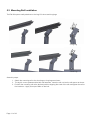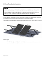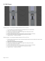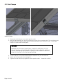
1
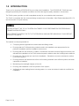
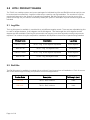
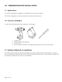
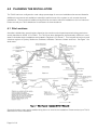
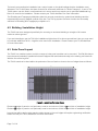
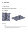
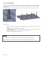
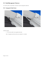
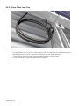
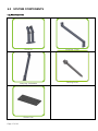
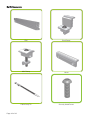
SECURE . UNIVERSAL . MOUNTING
Tilt Kit Installation Manual
1.0
INTRODUCTION ................................................................................................................................... 3
2.0
KITS / PRODUCT RANGE..................................................................................................................... 4
2.1
Leg Kits................................................................................................................................................. 4
2.2
Rail Kits................................................................................................................................................. 4
3.0
PREPARATION FOR INSTALLATION ................................................................................................... 5
3.1
Applications .......................................................................................................................................... 5
3.2
Tools for Installation.............................................................................................................................. 5
3.3
Additional Materials for Installation....................................................................................................... 5
4.0
PLANNING THE INSTALLATION .......................................................................................................... 6
4.1
Site Locations ....................................................................................................................................... 6
4.2
Building / Installation Height ................................................................................................................. 7
4.3
Solar Panel Layout................................................................................................................................ 7
4.4
General Installation Notes .................................................................................................................... 8
5.0
INSTALLATION ..................................................................................................................................... 9
5.1
Leg Kit Installation ................................................................................................................................ 9
5.1.1
Leg Kit Fixed ...................................................................................................................................................... 9
5.1.2
Leg Kit Adjustable ............................................................................................................................................ 10
5.2
Mounting Rail Installation.................................................................................................................... 11
5.3
Solar Panel Module Installation .......................................................................................................... 12
5.4
Mid Clamps ........................................................................................................................................ 13
5.5
End Clamps ........................................................................................................................................ 14
5.6
Cable Management Features............................................................................................................. 15
5.6.1
Integrated Cable Track .................................................................................................................................... 15
5.6.2
Clip-in Cable Loop Ties.................................................................................................................................... 16
6.0
SYSTEM COMPONENTS ................................................................................................................... 17
7.0
STANDARDS....................................................................................................................................... 19
8.0
CONTACT DETAILS............................................................................................................................ 19
Page 2 of 19
1.0 INTRODUCTION
Thank you for choosing LOCKSOLAR for your solar panel installation. The LOCKSOLAR, Tilt Kit has been
designed specifically for Australian conditions and uses the highest quality materials in construction.
The Tilt Kit system provides you with unequalled security for your valuable solar investment.
The Tilt Kit is compliant with the structural design requirements of Australian / New Zealand standard AS 1170
and comes with a 10 year warranty.
WARNING
INSTALLATION OF THE TILT KIT SYSTEM IS INTENDED TO BE PERFORMED BY PROFESSIONALLY
TRAINED INSTALLERS ONLY.
ANY ATTEMPT TO INSTALL THE TILT KIT SYSTEM BY AN UNQUALIFIED INDIVIDUAL COULD RESULT
IN INJURY OR DEATH
The installer is solely responsible for:
•
Complying with all applicable local and national building codes;
•
Ensuring that the Tilt Kit and other products used in the installation are appropriate for the
particular installation and the installation environment;
•
Ensuring that the roof structure, its rafters, connections and other structural support members can
withstand the installation of the Tilt Kit and solar panel modules under live building load conditions;
•
Ensuring only Tilt Kit parts are used in the installation. Substitution of parts could lead to a failure
in the Tilt Kit system;
•
Ensuring that the roof attachments of the roof mounting brackets have sufficient pullout and shear
capacities as installed;
•
Maintaining the watertight integrity of the roof;
•
Ensuring safe installation of all components of the system;
•
Verifying that other loading factors including water, ice, snow and seismic loads do not affect the
installation.
Page 3 of 19
2.0 KITS / PRODUCT RANGE
The Tilt Kit is a modular system and comes packaged in individual Leg Kits and Rail Kits so that each job can
be customized cost effectively. Leg Kits include all you need for one leg installation. The number of Leg Kits
required will depend on the amount of panels being installed. Rail Kits include all you need to secure your
panels to the legs. All you need to successfully install your system in Australian city and suburban regions are
included.
2.1 Leg Kits
The Leg Kit system is available in modular kits to suit different angular needs. There are two adjustable leg kits
to cater for angles between 10-30 degrees and 30-60 degrees. Two fixed angle kits at 30 degrees and 60
degrees are also available. Each Leg Kit comes with one long leg, one short leg and mounting components
required. The number of leg kits required for installation will depend on the amount of panels being installed.
Product Code
Description
Leg Angle
RIB-TILT-10-30
Tilt Kit – Leg, 10-30 degrees adjustable
10-30 degrees
RIB-TILT-30
Tilt Kit – Leg, 30 degrees fixed
30 degrees
RIB-TILT-30-60
Tilt Kit – Leg, 30-60 degrees adjustable
30-60 degrees
RIB-TILT-60
Tilt Kit – Leg, 60 degrees fixed
60 degrees
2.2 Rail Kits
The Rail Kit system is available in modular kits to suit both 3 and 4 panel per rail installations. Each kit comes
with 2 rails and enough mounting components to suit most applications.
Product Code
Description
Rail Length (mm)
RIB-2560
Tilt Kit – Rail, 2560mm
2560
RIB-3410
Tilt Kit – Rail, 3410mm
3140
Page 4 of 19
3.0 PREPARATION FOR INSTALLATION
3.1 Applications
The Tilt Kit is designed for installation on residential and commercial buildings.
The Tilt Kit is designed for mounting solar panel modules to flat steel roofs.
3.2 Tools for Installation
You will need the following tools for installing the Tilt Kit system.
1.
2.
3.
4.
Cordless drill
Protective gloves and clothing
Security driver
Various wood screw drivers, including Phillips head driver and Torx head drivers
3.3 Additional Materials for Installation
Our Tilt Kit system comes with just about everything you need to install the solar module panels. In order to
ensure the watertight integrity of the roof you will need waterproofing materials. Other tools and materials may
be required to prepare the roof structure for installation.
Page 5 of 19
4.0 PLANNING THE INSTALLATION
The Tilt Kit has been configured to meet a large percentage of common installation sites around Australia.
Additional components are available to extend the performance of the system to suit unusual sites and
installations. These consist of additional Leg Kits that are used to hold the installation to the roof structure.
Please consult your Tilt Kit distributor for assistance in these situations.
4.1 Site Locations
Australia is divided into several regions based on the maximum wind speed expected during peak storm
activity identified in AS/NZ 1170.2:2002. The Tilt Kit has been designed to be structurally sufficient in most
areas in Australia where installations are located in Regions A, B, W and C. This includes all major city and
suburban regions of Sydney, Melbourne, Brisbane, Adelaide, Canberra, Hobart and Perth. See figure 1 for
wind areas.
Figure 1 - Wind Regions - Australia AS/NZ1170.2:2.002
Some wind regions may require additional leg kits to be used in the installation. Please contact your Tilt Kit
distributor for more information.
Page 6 of 19
The terrain surrounding the installation has a major impact on the wind loadings that the installation must
withstand. The Tilt Kit system has been found to be structurally sufficient for Terrain Category 2, 3 and 4. The
Tilt Kit system can be used in rural locations but in some cases may require you to purchase additional Leg
Kits to be used in the installation. Please contact your Tilt Kit distributor for more information.
The Shielding and Topography Multipliers take into account protection by upwind local buildings and the
increased exposure by gradient upwind of the site. The Tilt Leg system has been found to be structurally
sufficient for Shielding and Topography multipliers of 1.
4.2 Building / Installation Height
The Tilt Kit has been designed specifically for mounting on enclosed building to a height of 20 meters
maximum above ground.
If you are intending to use the Tilt Kit for installations higher than 20 m above ground level, then you may need
to purchase additional Tilt Kit – Leg Kits to be used in the installation. Please contact your Tilt Kit distributor
for more information.
4.3 Solar Panel Layout
The Tilt Kit is a modular system to which a range of solar panel modules can be mounted. The Rail Kit clamps
the solar panel modules to parallel rails that are aligned with and tied structurally to the existing roof structure.
With the use of the Leg Kits
The Tile Kit needs to be sited within the perimeter of the roof and no closer to the roof edges than as follows;
Figure 2 – Installation Perimeter Zones
Distance A (edge of panel to roof perimeter) must be a minimum of 20% of X and 20% of installation height
Distance B (edge of panel to roof perimeter) must be a minimum of 20% of Y and 20% of installation height
Layouts that will locate the solar panel modules closer to the roof edges will require engineering verification.
Please consult your Tilt Kit distributor for further information.
Page 7 of 19
4.4 General Installation Notes
1. Mounting rails should align with the spacing of the battens / purlins of the roof
2. The spacing between the mounting rails shall not be less than 50% of the length of the solar panel
modules.
3. The mounting brackets should align with the rafters of the roof structure.
4. The mounting brackets shall be spaced evenly along the length of the mounting rail
5. The outer / end most mounting brackets shall be located evenly from the rail ends.
Page 8 of 19
5.0 INSTALLATION
Referring to the layout of the solar panel modules and Tilt Kit system, identify the positions of the mounting
rails and locate the roof structure for attachment.
5.1 Leg Kit Installation
The Leg Kit system provides the Tilt Legs pre-assembled in order to save on installation time. The mounting
legs are attached to the roof structure through the roof sheeting.
The placement and configuration of the different sized legs will determine the angle and direction of the panel.
5.1.1 Leg Kit Fixed
The Tilt Kit - Leg Kit Fixed allows the panel to be placed at fixed angles of 30 or 60 degrees depending on
which kit is purchased.
Assembly steps:
1. Mark the installation points and ensure that installation points are located over the centre of the
rafters.
2. Drill pilot holes in the steel roofing for the roofing screws.
3. Use the rubber pad supplied in the Leg Kit under each bracket and over the pilot holes to ensure a
watertight connection
4. Align the bracket along the line of the roof structure and mounting rail.
5. Secure the bracket with the roofing screws.
Page 9 of 19
5.1.2 Leg Kit Adjustable
The Tilt Kit - Leg Kit Adjustable allows the panel to be placed at angles between 10-30 degrees and 30-60
degrees depending on which kit is purchased. The long leg is supplied secured in the minimum length
configuration.
It is recommended to adjust the panel angle after the solar panel modules have been securely installed.
Assembly steps:
1. Mark the installation points and ensure that installation points are located over the centre of the
rafters.
2. Drill pilot holes in the roofing for the roofing screws.
3. Use the rubber pad supplied in the Leg Kit under each bracket and over the pilot holes to ensure a
watertight connection
4. Align the bracket along the line of the roof structure and mounting rail.
5. Secure the bracket with the roofing screws.
WARNING
ADJUSTABLE LEG 10-30 DEGREE SHOULD NOT BE EXTENDED FURTHER THAN 627mm.
ADJUSTABLE LEG 30-60 DEGREE SHOULD NOT BE EXTENDED FURTHER THAN 1100mm
Page 10 of 19
5.2 Mounting Rail Installation
The Rail Kit system easily attaches to the Leg Kit’s short and long legs.
- Long Leg
- Short Leg
Assembly steps:
1. Attach the mounting rail to the short legs or long legs as shown.
2. The leg kit comes preassembled with rail fasteners. Insert the rail nut into the rail space as shown.
3. Position the mounting rail at the desired position aligning the ends of the rail and tighten the rail to
the brackets – Apply a torque of 8Nm to the bolt.
Page 11 of 19
5.3 Solar Panel Module Installation
WARNING
ENSURE YOU FOLLOW ANY OF THE RECOMMENDATIONS AND INSTRUCTIONS OF THE SOLAR
PANEL MODULE SUPPLIER IN HANDLING AND INSTALLING THE SOLAR PANEL MODULES.
FOLLOW THE NEXT INSTRUCTIONS CAREFULLY. WHEN INSTALLING THE PANELS CORRECTLY
USING THE TILT KIT SYSTEM THE SOLAR PANEL MODULES WILL NOT BE DAMAGED.
The Solar panels are assembled to the Tilt Kit mounting rails 1 panel at a time starting from the center panel.
Use a suitable means to prevent the panels slipping from the frame during installation.
Once installed, the mounting clamps will hold the solar module panels in place. Until the clamps are securely
installed, the solar panel module needs to be appropriately secured.
Assembly steps:
1. Start by attaching a mid clamp to each mounting rail.
2. Using the following assembly steps for mid clamps and end clamps work from the center solar
panel module to the end solar panel modules.
Page 12 of 19
5.4 Mid Clamps
Assembly steps - For solar panel module thickness of 35 mm to 45mm:
1.
2.
3.
4.
5.
6.
7.
The mid clamps are preassembled with the fasteners for your convenience.
Attach the mid clamp to the mounting rail.
Position the mid clamp firmly against the edge of the solar panel module.
Turn the bolt to achieve a loose fit.
Slide the adjoining solar panel module along the rail and under the mid clamp.
Ensure that the mid clamp is tight against the solar panel modules.
Tighten the bolt. Torque bolt to 8 Nm.
Assembly steps - For solar panel module thickness of 45 mm to 55 mm:
1. Disassemble the fasteners from the mid clamp assembly and remove the aluminium spacer tube
from around the bolt.
2. Reassemble the fasteners to the mid clamp.
3. Attach the mid clamp to the mounting rail.
4. Position the mid clamp firmly against the edge of the solar panel module.
5. Turn the bolt to achieve a loose fit.
6. Slide the adjoining solar panel module along the rail and under the mid clamp.
7. Ensure that the mid clamp is tight against the solar panel modules.
8. Tighten the bolt. Torque bolt to 8 Nm.
Page 13 of 19
5.5 End Clamps
Assembly steps:
1. Determine the thickness of your solar panel module.
2. Start with the assembly of 1 set of end clamps on each of the mounting rails. The end clamps are
designed to suit a variety of solar panel module thicknesses from 35mm to 55mm. Set the end
clamp to suit the solar module panel.
WARNING
ENSURE THAT THE END CLAMP ONLY CONTACTS ONE POINT OF THE
MOUNTING RAIL AND THE FRAME EDGE OF THE SOLAR PANEL MODULE.
ADJUST THE END CLAMP HEIGHT TO ENSURE THAT THERE IS ONLY ONE
POINT OF CONTACT WITH THE MOUNTING RAIL.
3. The end clamps come preassembled with the fasteners for your convenience.
4. Attach the end clamp to the mounting rail.
5. Tighten the end clamp firmly against the solar panel module. Torque bolt to 8 Nm.
Page 14 of 19
5.6 Cable Management Features
The Tilt Kit system incorporates a number of cable management features;
5.6.1 Integrated Cable Track
Assembly steps:
1. Push loose cable into integrated cable slot
Note: Integrated cable slot will accommodate 2 to 3 cables.
Page 15 of 19
5.6.2 Clip-in Cable Loop Ties
Assembly steps:
1.
2.
3.
4.
Position Cable Loop Tie so that it runs parallel to rail and insert boss into rail clipping groove.
Maintaining some pressure, rotate clip clockwise to vertical, locked position.
Collect excess cable into loops and bend cable tie tail up to hold in place.
Push cable tie tail thru ratchet head and pull to tighten.
Page 16 of 19
6.0 SYSTEM COMPONENTS
Leg Kit Components:
Short Leg
Long Leg - Adjustable
Rubber Pad
Page 17 of 19
Long Leg - Fixed
Roofing Screw
Rail Kit Components:
Page 18 of 19
Rail
End Clamp
Mid Clamp
Joiner
Cable Loop Tie
Security Head Screw
7.0 STANDARDS
Australian/New Zealand Wind Loading Standard AS/NZ S1170.2.2002.
8.0 CONTACT DETAILS
T: 1300 199 233
F: 1300 779 882
INT: +61 41 99 22 777
E: [email protected]
www.locksolar.com
Page 19 of 19