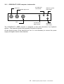
1
GYROPILOT 2 computer
product reference : 90-60-130
INSTALLATION GUIDE
nke – Sail racing
Z.I. Kerandré – Rue Gutenberg – 56700 HENNEBONT- FRANCE
http://www.nke.fr – After-sales service 0 892 680 656 : 0,34€/min.
SOMMAIRE
1
PRESENTATION ........................................................................................................... 3
2
INSTALLING THE HYDRAULIC UNIT........................................................................... 4
2.1
2.2
2.3
2.4
3
PREPARING THE RUDDER ARM ........................................................................................ 4
INSTALLATION OF THE HYDRAULIC LINEAR DRIVE ............................................................... 4
INSTALLATION OF THE HYDRAULIC PUMP ........................................................................... 6
INSTALLATION OF THE RUDDER ANGLE SENSOR ................................................................. 6
INSTALLATION AND CONNECTING THE COMPUTER .............................................. 8
3.1 PACKING LIST ................................................................................................................ 8
3.2 LIST OF ACCESSORIES .................................................................................................... 8
3.3 INSTALLING AND LOCATION OF THE COMPUTER GYROPILOT 2............................................. 8
3.4 ELECTRIC DIAGRAM OF GYROPILOT 2 RVP COMPUTER (REVERSIBLE PUMP) ....................... 9
3.5 ELECTRIC DIAGRAM GYROPILOT 2 CRP COMPUTER ....................................................... 11
3.6 CONNECTING THE POWER SUPPLY OF THE LINEAR DRIVE MOTOR ...................................... 13
3.7 CONNECTING THE COMPUTER TO TOPLINE BUS .............................................................. 14
3.8 TECHNICAL SPECIFICATION ........................................................................................... 15
3.9 SOFTWARE COMPUTER VERSION ................................................................................... 15
3.10 DIAGNOSTIC FOR 1ST LEVEL TROUBLES SHOOTING. ...................................................... 15
4
INITIALISATION OF THE COMPUTER ....................................................................... 16
4.1 INITIALISATION ............................................................................................................. 16
4.2 FIRST START-UP OF THE PILOT ...................................................................................... 17
-2-
Installation guide Gyropilot computer - 33-60-038-000
1 PRESENTATION
This installation guide gives you all information :
-
To install the computer Gyropilot 2
-
To install rudder angle sensor
-
To install de the hydraulic unit
-
To get the optimal performances from your pilot and your boat.
See the installation guide for fluxgate compass and multifonction Gyrographic.
Installation architecture
The presence of the equipment in the following diagram is for information only, and does
not represent the equipment of your installation.
Gyropilote Graphic
G5
True wind mode
Input NMEA
NMEA +
Reference
Page
Ent
True wind
-30°
1
-30°
1
nke
loch depth interface
90-60-450
Rudder angle
M
NMEA -
-10 0
10
Stop
Auto
Connecting box
90-60-417
nke
depth
loch
speedomètre
nke Gyropilot 2
RVP
GND
DATA black
Calculteur Gyro2
CRP
RVP
12VDC white
Embrayage
TOPLINE câble
20-61-001
Bus
Angle
Barre
Tiller
Pompe
réversible
Alim.
Masthead unit
Helm spindle
Rudder angle
hydaulic cylinder
Figure 1
-3-
Installation guide Gyropilot computer - 33-60-038-000
2 INSTALLING THE HYDRAULIC UNIT
Read this guide entirely before starting the installation .
Read the installation manual the hydraulic linear drive manufacture.
2.1 Preparing the rudder arm
If it is not possible to install the drive unit directly to the steering quadrant, then you will
have to buy and install a rudder arm for your rudder shaft. The rudder arm can be mounted
on the rudder shaft in any direction.
Make sure that the ruder arm can freely move 35° in both directions and that there is
enough room available to mount the drive unit and rudder angle sensor as per the following
sections.
Check with your boat manufacturer for special instructions on mounting autopilots to your
rudder shaft or your quadrant
Drill a ∅ 12mm hole to mount the hydraulic linear drive axis:
-
240mm from ruder axis for pack type 60
-
190mm from ruder axis pack type 40
-
170mm from ruder axis pack type 32
-
150mm from ruder axis pack type 27
-
129mm from ruder axis pack type mini
Rudder Arm
35°
35°
Rudder Shaft
2.2 Installation of the hydraulic linear drive
CAUTION:
The force developed by an hydraulic linear drive is very important and could occasion
important damage if it was badly installed.
The linear drive and the hydraulic pump must be positioned on an horizontal plan.
Make sure that the linear drive support is positioned in the way that the rudder arm or rudder
sector are in the same horizontal plan than the linear drive axis.
The fixing of the linear must be very rigid and you should not hesitate to strengthen it with a
stainless steel plate strongly attached to the boat.
-4-
Installation guide Gyropilot computer - 33-60-038-000
2.2.1 Dimensions for installation
Pack type
B
the rod half the way out
F
G
60
727mm
240mm
218mm
40
627mm
190mm
172,5mm
32
533mm
170mm
160mm
27
472mm
150mm
136,5mm
Mini
395mm
129mm
117mm
Rod tip
Rudder arm
2.2.2 Installation procedure
-
Put the rudder to the axis
-
Unscrew half the way the tip at the end of the drive rod, and pull the rod half the way out
such as the length between the axis of the linear support and the thrust axis is equal to
the rod length
-
Place the linear drive at 90° of the rudder arm
-
Fixed it with 4 stainless steel screws and nuts.
-
Grease the thrust axis of the linear drive and fix it on the rudder arm or rudder sector
with the supplied nylstop nut.
-
Adjust the rod tip on the same axis than the thrust axis and block it in position with the
counter-nut.
-
Insert the thrust axis in the rod tip and block it with a lynch pin.
Caution:
Check that the mechanical stop unit of rudder, stop the hydraulic unit. If the linear drive is
used as stop unit, it could be irremediably damaged.
-5-
Installation guide Gyropilot computer - 33-60-038-000
2.3 Installation of the hydraulic pump
Select a location where it is easy to access to the pump for maintaining : oil adjust, speed
setting.
Fix the pump with 4 screw and nuts ∅ 6mm, on an horizontal plan.
Not allowed
Correct mounting
Caution:
Don’t forget before start up , take of the tight cap, on the top of the oil tank, by the non-tight
cap supply with the hydraulic unit.
2.4 Installation of the rudder angle sensor
2.4.1 Precautions
-
The sensor arm must be able to move ±160° UNOBSTRUCTED.
-
When the rudder is centred line, the sensor arm must also be centred (in relation to the
axis screw head-see below).
-
Distance “A” must be equal to “B”.
-
The sensor connector must be 90° to the rudder arm when the rudder is centred.
-
It must be installed in a safe/dry location and away from interfering equipment (radio
receivers, compressors, speakers, generators, etc.)
-
The mounting location must be perfectly rigid and so that the sensor arm and the
rudder s arm are in the same horizontal plan.
-6-
Installation guide Gyropilot computer - 33-60-038-000
2.4.2 Installation procedure
1. Present the threaded rod in front of the rudder shaft, measure the maximum distance
where you can place the sensor, in function of the rod length. The sensor arm will have
to be able to rotate by 160° in both ways.
2. Measure precisely the distance A
3. Carefully centre the sensor so that the straight line going by the axis of the sensor arm
and the blocking nut is parallel to the rudder arm.
4. Drill a ∅ 7mm hole and mount the threaded connector arm to the rudder arm and the
sensor arm.
5. Then, cut the threaded rod such as value L = A-22mm
6. Mount the tips on the threaded rod, and block them with the counter nuts.
7. Before mounting the rod and tips on the connector arm, test manually your installation :
maintain the tips just above each connector, and move the rudder from Port to
starboard. If the parallelism is good, you can mount the tips on the connector arms.
Caution :
When the rudder is centred, the rudder arm of the angle sensor must also be centred and
parallel to the rudder arm.
The threaded rod must always be parallel to the linear drive axis. If not, this could seriously
damage the sensor.
The A lenght of the threaded rod must be less than 360mm.
-7-
Installation guide Gyropilot computer - 33-60-038-000
3 INSTALLATION AND CONNECTING THE COMPUTER
3.1 Packing list
-
One computer Gyropilote 2, with its connecting cables.
-
One installation guide.
-
One TOPLINE bus cable.
3.2 List of accessories
-
Standard terminal box TOPLINE bus : 90-60-121
Terminal box TOPLINE bus with NMEA input : 90-60-417
3.3 Installing and location of the computer Gyropilot 2
Precautions
The gyrometer sensor, essential to have good performances with the pilot, is integrated in
the computer Gyropilot 2. As this sensor is very sensible, the computer must be :
-
Mounted on a vertical wall,
-
It is screw with 4 screw ∅ 4mm and the cable outlet are to the bottom.
-
The location must be dry, above 50°C and not subjected to excessive vibrations
ATTENTION :
-
During fixing, tighten the nuts moderately. An excessive tightening can cause a break
of the case.
-
Do not use silicon mastic to fix the computer.
-8-
Installation guide Gyropilot computer - 33-60-038-000
3.4 Electric diagram of Gyropilot 2 RVP computer (reversible pump)
In this configuration, Gyropilot 2 RVP with reversible pump, the white wire are not used : put
an isolating protection on it.
nke
NMEA
- + - + - +-
+
-+-
²Blanc
Tresse
²Blanc
Tresse
noir
²Blanc
Tresse
noir
²Blanc
Tresse
noir
²Blanc
Tresse
noir
²Jaune
Vert
+- +
to BUS TOPLINE
Bus
power
supply
12 Vdc
nke Gyropilot 2
RVP
Calculteur Gyro2
CRP
RVP
Bus
Rudder
reference
Tiller
Clutch
Reversible
pump
Power
supply
fuse
or circuit breaker
white
Topline
BUS
Red
BLUE
Noir
+ Linear drive
- power supply
Brown
clutch
Hydraulic linear drive
Rudder arm
threaded rod
REVERSIBLE
PUMP
Rudder shaft
Rudder angle
sensor
-9-
Installation guide Gyropilot computer - 33-60-038-000
3.4.1
GYROPILOT 2 RVP computer : bottom side
Blue wire : ground
Hydraulic pump
TOPLINE BUS
Hydraulic power
supply
Rudder angle sensor
Two white wire : clutch coil
Tiller
Red wire : +
Two white wires
Brown wire :
+
Hydraulic pump
- 10 -
Black wire: ground
Hydraulic power
supply
Installation guide Gyropilot computer - 33-60-038-000
3.5 Electric diagram Gyropilot 2 CRP computer
nke
NMEA
-
+
- + - +- +-
+
-+-
²Blanc
Tresse
²Blanc
Tresse
noir
²Blanc
Tresse
noir
²Blanc
Tresse
noir
²Blanc
Tresse
noir
²Jaune
Vert
+
TOPLINE bus
Bus
power
Supply
12 Volts
nke Gyropilot 2
CRP
Calculteur Gyro2
CRP
RVP
Bus
Rudder
reference
Clutch
Tiller
Reversible
Pump
Supply
Circuit breaker
or fuse
Red
+ Linear drive
- power supply
Black
Topline
BUS
cable
Left solenoide
Right solenoide
Linear drive unit
Rudder arm
Threaded rod
Rudder
Shatf
Rudder angle
sensor
- 11 -
Installation guide Gyropilot computer - 33-60-038-000
3.5.1
GYROPILOT 2 CRP computer : bottom side
Two white wires :
Topline bus
Rudder angle sensor
Tiller
Left solenoide
Two white wires
Right solenoide
Black wire : ground
Power supply
Red wire : +
Power supply
The GYROPILOT 2 CRP computer is designed to drive the solenoids of an hydraulic
system ; This hydraulic system are generally mounted on big boat.
As the electric power of the solenoid are low, it is not necessary to connect the power
supply with higher electric wires diameter.
- 12 -
Installation guide Gyropilot computer - 33-60-038-000
3.6 Connecting the power supply of the linear drive motor
ATTENTION:
The Gyropilot 2 computer is designed to supply the linear power supply with 12VDC or
24VDC, but the TOPLINE bus must always de supply with 12VDC.
The supply power wires, from the computer and linear drive to the power battery, must be
as short as possible.
It is necessary to protect the linear drive power supply, using a fuse or a circuit breaker on
the red wire : 30A for a 12VDC supply and 16A for a 24VDC supply.
Recommended wire section to supply the power battery to the linear drive motor.
Length from battery to the linear drive
motor, via the Gyropilot 2 computer
Recommended section
3m
2,5 mm²
5m
4 mm²
7m
6 mm²
10 m
10 mm²
A too low section cause heating of cable and decrease the performances of the Gyropilot.
ATTENTION:
To avoid drop voltage on the TOPLINE BUS, it is strongly recommended to use two Batteries :
one for the linear drive unit power and another one for the TOPLINE BUS and the instrument. If
it is not possible on your boat, use a DC/DC 12V converter to separate the TOPLINE BUS
From the linear drive unit power.
- 13 -
Installation guide Gyropilot computer - 33-60-038-000
3.7 Connecting the computer to Topline bus
1. Make the computer bus cable run towards the TOPLINE terminal box of your
installation.
2. Connect the bus cable inside the terminal box :
If you reduce the length of the bus cable, strip and galvanise the wires before connecting
them inside the terminal box.
Gyropilote Graphic
G5
mode vent reel
nke Gyropilot 2
Consigne
ang vent rl
-30°
-30°
Page
Ent
1
1
RVP
COMPAS FLUXGATE
Angle de barre
Calculteur Gyro2
M
-10 0
CRP
RVP
nke
Embrayage
Bus
Angle
Barre
Tiller
Pompe
réversible
10
Stop
Auto
nke
Alim.
Alimentation 12Vdc
+
entrée NMEA
GND tresse
NMEA+
NMEA-
init
NMEA+
NMEA-
NOIR
GND
BLANC
NOIR
GND
BLANC
NOIR
GND
BLANC
GND
12V
DATA noir
12VDC blanc
boîte de connexion
90-60-417
Figure 3 : raccordement au bus TOPLINE
- 14 -
Installation guide Gyropilot computer - 33-60-038-000
3.8 Technical specification
-
Supply : 10 à 16VDC
Consumption : 50mA, without the hydraulic linear unit.
IP protection : IP67
Weight : 1kg, with cable
Dimensions : width = 210mm ; height = 134mm ; thickness = 42mm
Operating temperature : -10°C à +50°C
Temperature of storage : -20°C à +60°C
3.9 Software computer version
The software version is indicated on the label of the product.
3.10 Diagnostic for 1st level troubles shooting.
This chapter can help you rapidly resolve minor problems which do not require the
intervention of a specialist. Before contacting technical support, please check the
troubleshooting table below.
Problem
Possible causes and solutions
The Topline installation does not detect the Gyropilot Graphic
The bus cable is not or is badly connected to the terminal box : check the
plugging and the connection inside the terminal box. Check the state of
the cables : they must not show any sign of wear or cut.
The Gyropilot Graphic displays the message «
absent »
master Initialise the Gyropilot Graphic : see installation chapter.
The Gyropilot Graphic displays the message « bus error . Check that the black data wire is properly connected inside the terminal
box : see installation chapter.
The data cable (black) is in short-circuit »
The Gyropilot Graphic display three dashes «- - -» in place of Check the sensor of this channel, check the connection cable : it may be
damaged or disconnected.
the data of a channel.
The Gyropilot Graphic displays the message « bus error : It may be that there are two master displays (at address 1) on your
installation : check the addresses, if that is the case, reinitialise one of
conflict problem »
the displays.
The Gyropilot Graphic does not display the NMEA data : those Has the NMEA link been initialised ? see NMEA initialisation chapter
from the GPS for example.
The NMEA link is not or is badly connected to the terminal box : check
the connection of the Gyropilot Graphic and that of the NMEA
transmitter (GPS). see installation chapter.
The Gyropilot Graphic displays the message « low battery »
Check the voltage of your battery with a voltmeter : the operating voltage
must be above 10VDC. Check that the battery maintains the load.
The Gyropilot Graphic indicates « Error EPROM».
Reinitialise your Gyropilot Graphic. If the error message persists, please
contact your distributor.
If you do not manage to solve the problem, please contact your distributor.
- 15 -
Installation guide Gyropilot computer - 33-60-038-000
4 INITIALISATION OF THE COMPUTER
This chapter describes the initialisation of the Gyropilot 2 computer and the Gyropilot
Graphic. See also the Gyropilot Graphic user manual.
4.1 Initialisation
After installing the Gyropilot, you must initialise the whole of your pilot system. This is
required in order to perform the training of the Gyropilot computer: position the rudder at
the centre, then into limit stop on starboard side and finally into limit stop on port side, so
that the computer stores these positions of the rudder. These three rudder positions are
essential for the good operation of the cylinder of the pilot.
Follow the menu « Pilot Initialisation » of the Gyropilot Graphic which will guide you
along the procedure.
Procedure
− Using the Page key, select the Main menu page,
− then using the browser, select Configuration then Pilot initialisation,
− press the Ent key,
− the following message is displayed « This procedure will erase current settings.
Press the Ent key to start. Press the Page key to exit », press the Ent key,
the Gyropilot Graphic will guide you through the positioning of the rudder : follow the
indications :
Position the helm perfectly
in the centre then press
the Ent Key
Position the helm into
limit stop on starboard
side then press the Ent Key
Position the helm into limit
stop on port side then
press the Ent Key
− After performing an auto test, your pilot is initialised,
− Exit this menu by pressing the Page key.
CAUTION :
Inadequate initialisation of the pilot can lead to premature wear of the parts, poor heading
maintenance by the pilot and excessive electrical consumption.
If you are unsure about your setting, perform the initialisation once again.
- 16 -
Installation guide Gyropilot computer - 33-60-038-000
4.2 First start-up of the pilot
See the Gyropilot Graphic user manual.
Note that powering up or powering down your installation is done using the auxiliary switch
of the electric switchboard of your boat. Your installation must comprise two separate 12V
power supplies : one for power to the hydraulic pump and to the computer and the other for
the Gyropilot Graphic, the TOPLINE bus and the sensors. If it is not possible to have 2
batteries pack you must set up a converter 12V/12V.
CAUTION : It is imperative to start the first power supply before that of the TOPLINE bus.
- 17 -
Installation guide Gyropilot computer - 33-60-038-000
NOTES
________________________________________________________________________________________________
________________________________________________________________________________________________
________________________________________________________________________________________________
________________________________________________________________________________________________
________________________________________________________________________________________________
________________________________________________________________________________________________
________________________________________________________________________________________________
________________________________________________________________________________________________
________________________________________________________________________________________________
________________________________________________________________________________________________
________________________________________________________________________________________________
_______________________________________________________
- 18 -
Installation guide Gyropilot computer - 33-60-038-000
NOTES
________________________________________________________________________________________________
________________________________________________________________________________________________
________________________________________________________________________________________________
________________________________________________________________________________________________
________________________________________________________________________________________________
________________________________________________________________________________________________
________________________________________________________________________________________________
________________________________________________________________________________________________
________________________________________________________________________________________________
________________________________________________________________________________________________
________________________________________________________________________________________________
_______________________________________________________
- 19 -
Installation guide Gyropilot computer - 33-60-038-000
NOTES
________________________________________________________________________________________________
________________________________________________________________________________________________
________________________________________________________________________________________________
________________________________________________________________________________________________
________________________________________________________________________________________________
________________________________________________________________________________________________
________________________________________________________________________________________________
________________________________________________________________________________________________
________________________________________________________________________________________________
________________________________________________________________________________________________
________________________________________________________________________________________________
_______________________________________________________
- 20 -
Installation guide Gyropilot computer - 33-60-038-000