
1
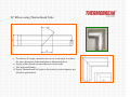
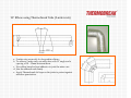
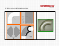
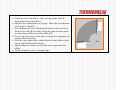
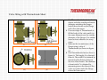
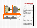
Installation Manual - Fittings
Fabrication from Thermobreak Tube and Sheet
• 90˚ Elbow with Thermobreak Tube …………………………………….
• 45˚ Elbow with Thermobreak Tube …………………………………….
• 90˚ Elbow in 2 miter cuts with Thermobreak Tube……………………
• 45˚ Elbow in 2 miter cuts with Thermobreak Tube……………………
• 90˚ Elbow in 3 miter cuts with Thermobreak Tube……………………
• 45˚ Elbow in 3 miter cuts with Thermobreak Tube……………………
• Tee fitting using Thermobreak Tube……………………………………
• 90˚ Elbow with Thermobreak Sheet……………………………………..
• Valve fitting with Thermobreak Sheet………………………………….
90˚ Elbow using Thermobreak Tube
a. To achieve 45˚ angle, use miter box or cut in an angle to achieve
the outer diameter of the insulation as illustrated above
b. Apply rubber based solvent adhesive to both ends
c. Join both ends firmly
d. Apply Thermobreak foil tape on the joints to protect against any
moisture penetration
45˚ Elbow using Thermobreak Tube
a. To achieve 22.5˚ angle, use miter box or cut in an angle to
achieve the 1/3rd of the outer diameter of the insulation as
illustrated above (Note: The 1/3rd of the outer diameter cut is
approximate values to achieve 22.5˚ angle)
b. Apply rubber based solvent adhesive to both ends
c. Join both ends firmly
d. Apply Thermobreak foil tape on the joints to protect against any
moisture penetration
90˚ Elbow using Thermobreak Tube (2-miter cuts)
a. 2-miter cuts are mostly for long radius elbows
b. To achieve 2 miter cuts, use miter box with 15˚ angle and a
spacing of 10 – 15mm between them.
c. Use rubber based solvent adhesive to joint the miter cuts
d. Join the adhered ends firmly
e. Apply Thermobreak foil tape on the joints to protect against
moisture penetration.
90˚ Elbow using Thermobreak Tube (3-miter cuts)
a. 3-miter cuts are mostly for short radius elbows
b. To achieve 3 miter cuts, use miter box with 11.25˚ angle and a
spacing of 10 – 15mm between them.
c. Use rubber based solvent adhesive to joint the miter cuts
d. Join the adhered ends firmly
e. Apply Thermobreak foil tape on the joints to protect against
moisture penetration.
Tee using Thermobreak Tube
a.
b.
c.
d.
Cut the two tubes as per drawing illustrated above
Apply rubber based solvent adhesive to both ends
Join both ends firmly
Apply Thermobreak foil tape on the joints to protect against any
moisture penetration
90˚ Elbow using with Thermobreak Sheet
a. Check the size of the elbow – short or long radius. Take R1
measurement as shown above.
b. Measure the circumference of the pipe. Halve the circumference
of the pipe to obtain R2 .
c. Use a reference point on Thermobreak sheet as the center and
draw an arc using R1 as radius. Using the same reference point
as center draw another arc with radius of R2.
d. Cut out the first section of the elbow. Using this as template, cut
another identical section
e. Glue the outer edges with a rubber based solvent adhesive and
tape it with Thermobreak foil tape.
f. Apply adhesive at seam on other side and wrap around the
elbow.
g. Trim both ends to give it a straight edge.
Valve fitting with Thermobreak Sheet
(i)
(iii)
(ii)
(iv)
a. Cut Thermobreak sheet in to donut
shapes with the outside and inside
diameter matching the flanges.
Install these donuts on the flange
and valve stem areas.
b. Use scar strips of Thermobreak to
fill the body of the valve until it is
the same dimension as the outside
diameter of the flanges. Use rubber
based solvent adhesive for scrap
strips.
c. Measure the circumference of the
flange using a strip of
Thermobreak (as shown in figure
iii)
d. Cut Thermobreak sheet as show in
figure iv. The length A is obtained
from iii. The width B is obtained by
measuring the distance between
the two outer donuts. The diameter
of semi-circle C is obtained by
measuring across the throat of the
valve at a point under the flange
where the stem enters.
(v)
(vi)
(vii)
(viii)
e. The cut sheet (iv) is installed
around the valve body using a
rubber based solvent adhesive.
f. The last piece of insulation to wrap
the bonnet area is made as show in
vii & viii.
g. The overall length C is determined
by wrapping Thermobreak on the
bonnet.
h. L1 is obtained from the middle of
the valve body till the neck of
bonnet area (as shown in vi).
i. L2 is obtained by measuring the
outer surface of the insulated valve
to the bonnet neck area (as shown
in vi).
j. Y is the difference between L1 & L2.
k. Cut the Thermobreak sheet in size
C x L1.
l. Divide it in to 4 quarters, at the
end of the 1st , 2nd and 3rd quarter
use Y as the distance from top and
use this as reference to draw an
arc. Connect the arc by staright
lines and cut Thermobreak along
these marks and install it on the
bonnet area.


![MANUAL DON100 [00].indd](http://vs1.manualzilla.com/store/data/006095799_1-d1aaff0cf1c228ce06e57a23b8945995-150x150.png)
