1
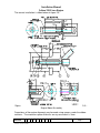
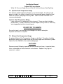
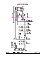
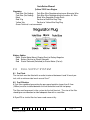
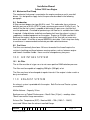
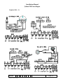
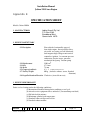
Installation Manual
Jabiru 2200 Aero Engine
INSTALLATION MANUAL
FOR
JABIRU 2200 AIRCRAFT ENGINE
This Manual has been prepared as a guide to correctly install the Jabiru 2200
engine into an airframe.
Should you have any questions or doubts about the contents of this manual, please
contact Jabiru Aircraft Pty Ltd.
Applicable to Jabiru 2200A, 2200B & 2200J Models
REVISION
0
1
2
3
Dated : 13 Nov 2000
L:\files\engine_manuals\2200_engine_manuals\Installation Manual 2200 (Issue 3).doc
Print Date: 12/11/02 10:35 AM
Page: 1
Installation Manual
Jabiru 2200 Aero Engine
Table of Contents
1.0
DESCRIPTION_______________________________________________________ 5
2.0
SPECIFICATIONS ___________________________________________________ 5
3.0
DIMENSIONS _______________________________________________________ 6
4.0
DENOMINATION OF CYLINDERS _____________________________________ 7
5.0
ENGINE MOUNT ____________________________________________________ 7
6.0
CONTROLS _________________________________________________________ 9
6.1 Throttle and Choke _________________________________________________________9
6.2 Master Switch, Ignition Switches and Starter Button _____________________________9
7.0
INSTRUMENTS ______________________________________________________ 9
7.1 Electronic Tachometer ______________________________________________________9
7.2 Oil Temperature Gauge______________________________________________________9
7.3 Oil Pressure Gauge _________________________________________________________9
7.4 Cylinder Head Temperature Gauge___________________________________________10
7.5 Exhaust Gas Temperature Gauge ____________________________________________10
8.0
ELECTRICAL EQUIPMENT __________________________________________ 12
8.1 Alternator ________________________________________________________________12
8.2 Regulator_________________________________________________________________12
8.3 Ignition __________________________________________________________________12
8.4 Starter Motor _____________________________________________________________13
8.5 Battery___________________________________________________________________13
8.6 Additional Wiring Information ______________________________________________13
9.0
FUEL SUPPLY SYSTEM _____________________________________________ 14
9.1 Fuel Tank ________________________________________________________________14
9.2 Fuel Filtration_____________________________________________________________14
9.3 Mechanical Fuel Pump _____________________________________________________15
9.4 Carburettor_______________________________________________________________15
9.5 Fuel Lines ________________________________________________________________15
10.0 AIR INTAKE SYSTEM _______________________________________________ 15
10.1 Air Filter ________________________________________________________________15
11.0 EXHAUST SYSTEM _________________________________________________ 15
REVISION
0
1
2
3
Dated : 13 Nov 2000
L:\files\engine_manuals\2200_engine_manuals\Installation Manual 2200 (Issue 3).doc
Print Date: 12/11/02 10:35 AM
Page: 2
Installation Manual
Jabiru 2200 Aero Engine
12.0 COOLING SYSTEMS ________________________________________________ 16
13.0 PROPELLER SELECTION____________________________________________ 16
14.0 AUXILIARY UNITS__________________________________________________ 16
Appendix A ______________________________________________________________ 17
Appendix B ______________________________________________________________ 18
LIST OF EFFECTIVE PAGES
The dates of issue for original & revised pages are:
Page
Issue
Date
1
2
3
4
5
6
7
8
9
10
11
12
13
14
15
16
17
18
19
20
3
3
3
3
3
3
3
3
3
3
3
3
3
3
3
3
3
1
3
3
13/11/00
13/11/00
13/11/00
13/11/00
13/11/00
13/11/00
13/11/00
13/11/00
13/11/00
13/11/00
13/11/00
13/11/00
13/11/00
13/11/00
13/11/00
13/11/00
13/11/00
13/11/00
13/11/00
13/11/00
Issue Notes:
Issue 3 Raised to Include Revised CHT specification for New Heads. Effects Appendix B data Only
REVISION
0
1
2
3
Dated : 13 Nov 2000
L:\files\engine_manuals\2200_engine_manuals\Installation Manual 2200 (Issue 3).doc
Print Date: 12/11/02 10:35 AM
Page: 3
Installation Manual
Jabiru 2200 Aero Engine
1 .0
-
4 Stroke
4 Cylinder Horizontally Opposed
1 Central Camshaft
Push Rods
Over Head Valves (OHV)
Ram Air Cooled
Wet Sump Lubrication
Direct Propeller Drive
Dual Transistorised Magneto Ignition
Integrated AC Generator
Electric Starter
Mechanical Fuel Pump
Naturally Aspirated – 1 Pressure Compensating Carburettor
6 Bearing Crankshaft
2 .0
-
DE S CR I P T I ON
S P E CI F I CAT I ONS
Displacement
Bore
Stroke
Compression Ratio
Direction of Rotation
of Prop Shaft
Ramp Weight
:
:
:
:
2200 cc
97.5 mm
74 mm
8.3:1 Note:
:
:
:
:
:
-
Ignition Timing
Firing Order
DC Output
Fuel Consumption
@ 75% Power
Fuel
Oil
Clockwise – Pilot’s view – Tractor Applications
60 kg (132 lbs) Complete including Exhaust,
Carburettor, Starter Motor, Alternator & Ignition
System.
25o BTDC
1–3–2–4
10 Amps
-
Oil Capacity
Spark Plugs
:
:
-
REVISION
0
1
2
as standard.
:
:
:
3
Eng S/N 832 on have lowered compression again
15 l/hr (4 US gal/hr)
AVGAS 100/130
Aero Oil W Multigrade 15W-50, or equivalent
Lubricant complying with MIL-L-22851C, or
Lycoming Spec. 301F, or Teledyne –
Continental Spec MHF-24B
2.3 1 (2.2 quarts)
NGK D9EA – Automotive
Dated : 13 Nov 2000
L:\files\engine_manuals\2200_engine_manuals\Installation Manual 2200 (Issue 3).doc
Print Date: 12/11/02 10:35 AM
Page: 4
Installation Manual
Jabiru 2200 Aero Engine
3 .0
DI ME NS I ONS
Drawing 9404041/1 Engine Dimensions
REVISION
0
1
2
3
Dated : 13 Nov 2000
L:\files\engine_manuals\2200_engine_manuals\Installation Manual 2200 (Issue 3).doc
Print Date: 12/11/02 10:35 AM
Page: 5
Installation Manual
Jabiru 2200 Aero Engine
4 .0
DE NOMI NAT I ON OF CY L I NDE R S
Cylinder Firing Order: 1 – 3 – 2 – 4
5 .0
E NGI NE MOU NT
The design of the engine mount must not only take into account the structural
loadings but must make allowances for accessibility of components and the removal
of equipment located at the rear of the engine.
The engine has four engine mounting points located at the rear of the engine (refer
to figure 1.0) from which the engine is to be mounted. An optional bed mount may
be fitted.
Figure 1.0 – Engine Mount Point Locations
REVISION
0
1
2
3
Dated : 13 Nov 2000
L:\files\engine_manuals\2200_engine_manuals\Installation Manual 2200 (Issue 3).doc
Print Date: 12/11/02 10:35 AM
Page: 6
Installation Manual
Jabiru 2200 Aero Engine
The correct installation is shown below in figure 2.0
Figure
Engine Mount Assembly
2.0 –
Corrections of the engine alignment may be made using spacers under the rubber
cushions. The maximum spacer thickness on any one mount is 3mm.
REVISION
0
1
2
3
Dated : 13 Nov 2000
L:\files\engine_manuals\2200_engine_manuals\Installation Manual 2200 (Issue 3).doc
Print Date: 12/11/02 10:35 AM
Page: 7
Installation Manual
Jabiru 2200 Aero Engine
6 .0
CONT R OL S
This section comprises of the mechanical controls and electrical switches.
6.1 Throttle and Choke
Provisions for the connection of the throttle and choke are made on the carburettor.
Note: Since a pressure compensating carburettor is used there is no mixture control.
6.2 Master Switch, Ignition Switches and Starter Button
The switches are connected as shown by the circuit diagram, on Page 10.
7 .0
I NS T R U ME NT S
7.1 Electronic Tachometer
The tachometer uses a pick-up mounted on the alternator mounting bracket which
‘counts’ the teeth of the flywheel ring gear. Jabiru Part No. PI10772N is the
recommended tachometer. Note: On later engines tacho picks up on 2 metal tabs
attached to the inside of the flywheel. Pickup is of induction sender type.
Tachometer Wiring
3
Tachometer Negative (3) to Earth
4
Tachometer Positive (4) to Instrument
8
Tachometer to Red Wire tachometer pick-up
7
Tachometer to Black Wire tachometer pick-up
7.2 Oil Temperature Gauge
The Oil Temperature Gauge uses an electric probe mounted in the base of the
sump. Jabiru Part No. PI10752N is recommended.
Oil Temperature Wiring
Black Oil Temperature Gauge Negative to Earth
Red Oil Temperature Gauge Positive to Instrument
White Oil Temperature Gauge Sensor (S) to Oil Temperature Sensor
(Lower Left Eng Sump)
7.3 Oil Pressure Gauge
An electric oil pressure sender is fitted to the engine for an Oil Pressure Gauge.
Jabiru Part No. PI10762N is the recommended gauge.
Oil Pressure Wiring
Black Oil Pressure Gauge Negative to Earth
Red Oil Pressure Gauge Positive to Instrument
REVISION
0
1
2
3
Dated : 13 Nov 2000
L:\files\engine_manuals\2200_engine_manuals\Installation Manual 2200 (Issue 3).doc
Print Date: 12/11/02 10:35 AM
Page: 8
Installation Manual
Jabiru 2200 Aero Engine
White Oil Pressure Gauge Sensor (S) to Oil Pressure Sensor (Fwd Top Eng)
7.4 Cylinder Head Temperature Gauge
The Cylinder Head Temperature Gauge uses a thermocouple. An audit must be
done to establish the hottest cylinder and the thermocouple probe should be fitted
under the exhaust spark plug on that cylinder. Jabiru Part No. PI10732N is the
recommended gauge.
Cylinder Head Temperature Wiring
Loom and sensor is supplied with the instrument. These must be installed as
per directions. If cable is too long it must be looped as many times as necessary
and strapped behind the instrument panel.
DO NOT CUT TO LENGTH
Ensure that wire is not chaffing on the fibreglass air duct or cooing fins.
No power connection is required.
7.5 Exhaust Gas Temperature Gauge
An optional Exhaust Gas Temperature Gauge can be fitted. The probe should be
positioned 100mm from the port flange on the exhaust pipe of a convenient cylinder.
Jabiru Part No. PI0325N is the recommended gauge.
SCAT HOSE
Remove at each 50 hourly inspection one end of each scat hose. Inspect for holes,
leaks and condition of helical wound in a wire former. Replace if any signs of
corrosion is evident.
REVISION
0
1
2
3
Dated : 13 Nov 2000
L:\files\engine_manuals\2200_engine_manuals\Installation Manual 2200 (Issue 3).doc
Print Date: 12/11/02 10:35 AM
Page: 9
Installation Manual
Jabiru 2200 Aero Engine
REVISION
0
1
2
3
Dated : 13 Nov 2000
L:\files\engine_manuals\2200_engine_manuals\Installation Manual 2200 (Issue 3).doc
Print Date: 12/11/02 10:35 AM
Page: 10
Installation Manual
Jabiru 2200 Aero Engine
8 .0
E L E CT R I CAL E QU I P ME NT
8.1 Alternator
The alternator fitted to the Jabiru 2200 engine is a single phase, permanently
excited with a regulator. The rotor is mounted on the flywheel with the stator
mounted on the alternator mount plate at the back of the engine. The alternator
mount plate is also the mount for the ignition coils and the vacuum pump.
Specifications
Power (Max): 120W Continuous
Note: The electrical system is Negative Earth.
8.2 Regulator
The regulator has been selected to match the voltage and current of the integral
alternator. Only Jabiru Part No. PI10652N should be used. (The regulator output
voltage is 14 volts + 0.8 volt.)
Recommended wiring of regulator is positive and negative of the regulator directly to
the battery
8.3 Ignition
The ignition unit has dual breakerless transistorised ignition with the magnets
mounted on the flywheel and the coils mounted on the alternator mount plate.
The current from the coils flows to the distributor from where it is distributed to the
spark plugs. (See also Regulator Wiring at Page 12.)
The ignition is turned off by grounding the coils via the ignition switches.
The ignition is timed to 25o BTDC
The temperature limit for the ignition coils is 100oC. This should be checked by the
installer. It is recommended that pipes of 12mm dia be fitted to the top rear of each
air duct directing air onto the coils for cooling purposes.
From serial number 1205 engines require coil gap to flywheel of 0.80mm
(0.032 “). Early engines required only 0.25mm (0.010 “) gap.
From serial number 1292 coils set at 0.25mm (0.010”).
Transistorised Ignition 1 Wiring
No. 1 Switch – Upper to Left Transistorised Ignition
No. 1 Switch – Lower to Earth
Switch Open for Ignition ON, closed for Ignition OFF.
Transistorised Ignition 2 Wiring
No. 2 Switch – Upper to Right Transistorised Ignition
No. 2 Switch – Lower to Earth
Switch Open for Ignition ON, closed for Ignition OFF.
REVISION
0
1
2
3
Dated : 13 Nov 2000
L:\files\engine_manuals\2200_engine_manuals\Installation Manual 2200 (Issue 3).doc
Print Date: 12/11/02 10:35 AM
Page: 11
Installation Manual
Jabiru 2200 Aero Engine
8.4 Starter Motor
The starter is mounted on the top of the engine and drives the ring gear on the
flywheel. The motor is activated by engaging the starter button (the master switch
has to be ON) which trips the solenoid, hence current flows from the battery to the
motor. The cable from Battery to starter should be minimum 16mm2 copper.
Starter Wiring
Starter Button Switch (lower) to Main Bus
Starter Button Switch (upper) to Start Solenoid (through Grommet)
8.5 Battery
The battery should be of a light weight, 12V, 20 Ah type able to accept a charging
voltage up to 14 V (+ 0.8V) and a 10 AMP Input.
8.6 Additional Wiring Information
Engine Hourmeter Wiring
Red
Hourmeter Positive to Positive
Black
Oil Pressure Switch to Engine Sump Bolt
Black
Hourmeter to Oil Pressure Switch (Fwd Eng Left)
Earth Wiring
Black
Black
Battery Earth Negative to Firewall Earth (Engine Bay)
Battery Earth Negative to Earth Bus
Master Wiring
Red
Red
Red
Red
Starter Solenoid to Main Fuse
Main Fuse to Master Switch (Lower)
Master Switch (Upper) to Main Bus
Main Bus to Red on Regulator
Fuel Pump Wiring
Red
Main Bus to Fuel Pump Fuse
Red
Fuel Pump Fuse to Fuel Pump Switch (Lower)
Red
Fuel Pump Switch (Upper) to fuel Pump (Red Wire)
Black
Fuel Pump (Black Wire) to Earth Bus
REVISION
0
1
2
3
Dated : 13 Nov 2000
L:\files\engine_manuals\2200_engine_manuals\Installation Manual 2200 (Issue 3).doc
Print Date: 12/11/02 10:35 AM
Page: 12
Installation Manual
Jabiru 2200 Aero Engine
Regulator
Pale Blue (No Coding)
Pale Blue Wire Regulator plug to one Alternator Wire
Pale Blue (No Coding)
Pale Blue Wire Regulator plug to the other Alt. Wire
Black
Black Wire Regulator Plug to Earth
Red 10 g
Positive to Red Wire Reg. Plug
Yellow 16g
Positive to Yellow Wire Reg Plug
Green Terminal is not connected.
Battery Cables
Black Starter Motor Mount (Engine Rear) to Battery Negative
Red Battery Positive to Starter Solenoid
Red Starter Solenoid (Switched) to Starter Motor (Part of)
9 .0
F U E L S U PPL Y S Y S T E M
9.1 Fuel Tank
The fuel tank must be fitted with an outlet strainer of between 8 and 16 mesh per
inch, with a minimum total mesh area of 5 cm2.
9.2 Fuel Filtration
A Fuel filter capable of preventing the passage of particles larger than 0.1mm
(100um) must be installed between the fuel tank outlet and the fuel pump.
The filter must be present in the system for the fuel flow test. The size of the filter
should give consideration to allow adequate flow with a used filter.
A Ryco Z15 or similar filter has been used successfully.
REVISION
0
1
2
3
Dated : 13 Nov 2000
L:\files\engine_manuals\2200_engine_manuals\Installation Manual 2200 (Issue 3).doc
Print Date: 12/11/02 10:35 AM
Page: 13
Installation Manual
Jabiru 2200 Aero Engine
9.3 Mechanical Fuel Pump
The mechanical fuel pump is mounted on the engine crankcase and is camshaft
driven. It is designed to supply fuel at the pressure described in the following
paragraph.
9.4 Carburettor
A Bing constant depression type 94/40 is used. This carburettor has a minimum
delivery pressure of 5 kPa (0.75 Psi) and a maximum pressure of 20 kPa (3 psi). To
confirm that the fuel system is capable of delivering this pressure a fuel flow test
must be performed. A method for performing a fuel flow test is available from Jabiru
if required. A drip deflector to deflect overflowing fuel from the exhaust system is
supplied as standard equipment on the engine. Engines to S/N 698 used 64/32.
Because the engine is dyno run some adjustment of the 7mm idle set screw may
have to be made. A hot idle of around 900RPM is desirable. Earth strap from carby
to crankcase is recommended to eliminate possible radio interference.
9.5 Fuel Lines
Fuel lines are nominally 6mm bore. All hoses forward of the firewall require fire
resistant sheathing and those between moving sections such as between engine
and firewall should be flexible. Hoses must be changed every two years.
1 0 .0
AI R I NT AK E S Y S T E M
10.1 Air Filter
The air filter must be of a type so as to not cause positive RAM induction pressure.
The filter must be capable of supplying 250 kg/hr (550 pph) of air
The filter may have to be changed at regular intervals if the engine is to be used in a
dusty environment.
1 1 .0
E X H AU S T S Y S T E M
An exhaust system is provided with the engine. Both Pusher and Tractor systems
are available.
Muffler Volume – Capacity 3 litres
Back pressure at Takeoff Performance – Max 0.2 bar (2.9 psi) – readings taken
70mm from muffler flange connections.
Exhaust Gas Temperature (EGT) - Nominal 650o – 750o (1202oF – 1382oF)
measured 100mm from the exhaust manifold flange.
REVISION
0
1
2
3
Dated : 13 Nov 2000
L:\files\engine_manuals\2200_engine_manuals\Installation Manual 2200 (Issue 3).doc
Print Date: 12/11/02 10:35 AM
Page: 14
Installation Manual
Jabiru 2200 Aero Engine
1 2 .0
COOL I NG S Y S T E MS
The engine should be installed using RAMAIR ducts provided with the engine.
Each duct must have a 25mm hole at the inside top front to bleed air over the
crankcase.
Cylinder and cylinder head cooling is achieved by ducting air over the cylinders.
The Static Air Pressure inside the cooling ducts must not be lower than 4.3cm (1.7”)
water gauge at 1.3 times the stall speed.
An oil cooler should be installed and sized to achieve oil temperatures within the
engine limits. Hoses should be nominally 8mm (5/16”) bore. Hoses must be
changed every two years.
The limits in the Specification Sheet, contained in Appendix B, must be strictly
adhered to. Warranty will not be paid on engine damage attributed to
overheating of cylinders or oil.
The cooling ducts provided are only a starting point in establishing effective engine
cooling. The ducts may require to be increased in size and additional baffles
provided to achieve the specified maximum cylinder head temperature of 175oC.
1 3 .0
P R OP E L L E R S E L E CT I ON
The hub of the propeller must be drilled with holes to match the flange. The
propeller must be carefully selected to match the airframe and the engine.
Propellers up to 1727mm (68”) in diameter and between 762mm (30”) and 1219mm
(48”) in pitch may be used. The propeller flange is drilled with 6 holes at both 4”
PCD and 100mm PCD.
Moment of inertia up to 0.25 kgm2
Applications outside this range should be referred to Jabiru.
1 4 .0
AU X I L I AR Y U NI T S
Vacuum Pump
For the installation of an artificial horizon and/or a direction gyro a vacuum pump is
necessary. A Tempest 212CW (or equivalent) vacuum pump can be fitted to the
alternator mounting plate and directly coupled to the crankshaft. The drive pad is
dry.
The pad and spline are SAE Standard.
REVISION
0
1
2
3
Dated : 13 Nov 2000
L:\files\engine_manuals\2200_engine_manuals\Installation Manual 2200 (Issue 3).doc
Print Date: 12/11/02 10:35 AM
Page: 15
Installation Manual
Jabiru 2200 Aero Engine
Appendi x A
REVISION
0
1
2
3
Dated : 13 Nov 2000
L:\files\engine_manuals\2200_engine_manuals\Installation Manual 2200 (Issue 3).doc
Print Date: 12/11/02 10:35 AM
Page: 16
Installation Manual
Jabiru 2200 Aero Engine
Appendi x B
SPECIFICATION SHEET
Models: Jabiru 2200A
1. MANUFACTURER
Jabiru Aircraft Pty Ltd,
P.O. Box 5186,
Bundaberg West,
Queensland 4670
2. ENGINE PARTICULARS
2.1 Description
Four cylinder, horizontally opposed,
four stroke engine, direct propeller drive,
air cooled, wet sump, pressure lubricated,
dual magneto high voltage transistorised
contactless ignition, 1 x constant-pressure
carburettor, electric starter, generator,
mechanical fuel pump. Vacuum pump
2209 cm2
2.2 Displacement
97.5 mm
2.3 Bore
74 mm
2.4 Stroke
8.3 : 1 s/n 1004 onwards have 8:1
2.5 Compression Ratio
60 kg (includes exhaust, starter, flywheel
2.7 Net Dry Weight
alternator)
2.8 Propeller Rotation Direction Clockwise (viewed from rear)
3. ENGINE PERFORMANCE
Static sea level ratings under the following conditions:(a) International Standard Atmospheric conditions at sea level.
(b) Aircraft service equipment drives unloaded. (Vacuum Pump not fitted)
(c) Full rich fuel/air mixture.
(d) Maximum cylinder head temperature.
(e) Standard Jabiru air filter and cold air.
(f) Standard exhaust muffler.
REVISION
0
1
2
3
Dated : 13 Nov 2000
L:\files\engine_manuals\2200_engine_manuals\Installation Manual 2200 (Issue 3).doc
Print Date: 12/11/02 10:35 AM
Page: 17
Installation Manual
Jabiru 2200 Aero Engine
3.1 Engine Ratings
3.1.1
3.1.2
3.1.3
Takeoff/Max Continuous
Fuel Consumption
Oil Consumption
80 HP / 3300 RPM
21 L/hr @ Takeoff/Max Continuous Rating
0.1 L/hr (max)
4. OPERATING LIMITATIONS
4.1 RPM
Continuous
:
3300 RPM / Full Throttle
4.2 Engine Cooling
Cylinder Head Temperature measured under exhaust spark plug.
Condition
Maximum Peak Temperature
Continuous Operation
Applicable to Engines with
Cylinder Heads P/No
478000N, and 4779002
Fitted1
2008C
1808C
Engines with All other Types
of Heads Fitted
1758C
1508C
4.3 Fuel
4.3.1 Specifications
Avgas 100LL & Avgas 100/130
Leaded and Unleaded Automotive Gasoline above 95 Octane Ron
4.3.2 Pressure to Carburettor (above ambient)
(a) Maximum
(b) Minimum
20 kPa
5 kPa
WARNING – When using auto fuels, ensure all components of the fuel delivery system are
cooled to prevent fuel vaporization.
4.4 Oil
4.4.1 Specifications
Aero Oil W Multigrade 15W-50,
or equivalent Lubricant complying with
MIL-L-22851C, or
Lycoming Spec. 301F, or
1
Cylinder heads P/No 4779002, and 478000N, have more cooling fin area, and a different construction.
REVISION
0
1
2
3
Dated : 13 Nov 2000
L:\files\engine_manuals\2200_engine_manuals\Installation Manual 2200 (Issue 3).doc
Print Date: 12/11/02 10:35 AM
Page: 18
Installation Manual
Jabiru 2200 Aero Engine
Teledyne - Continental Spec MHF-24B
4.4.2 Inlet Temperature
Minimum for Operation
Maximum
Continuous
4.4.3 Pressure
Normal Operations
Idle
Starting & Warm Up
15oC
118oC
80oC – 100oC
Min
Max
Min
Max
220 kPa
525 kPa
80 kPa
525 kPa
5. TYPES OF PROPELLER
Fixed pitch wooden propellers.
Maximum propeller diameter 1727mm (68").
6. EQUIPMENT
(a) The following equipment is included in the engine approval:Carburettor:
1 x Bing constant Pressure carburettor type 94/40
Main jet is Bing 255 .
Main jet 2.10 mm or Bing metered jet marked 230 (64/32)
Fuel Pump:
Mechanical, Jabiru P/N PG10332N
Ignition System:
Jabiru dual magneto, high voltage transistorised,
contactless P/N PI10522N
Spark Plugs:
NGK D9EA
Alternator:
Integrated Jabiru, permanent magnet single phase
alternator, P/N 4532064/4535064 with regulator rectifier
P/N PI10652N.
Starter:
Jabiru 12V/1.0 kW, engagement via reduction gear and
freewheel. Bosch tpye p/n 4776093
(b) The following optional equipment may be driven by or fitted to the engine subject to the
type number being included in the approved Jabiru Aircraft Pty Ltd engine specification:REVISION
0
1
2
3
Dated : 13 Nov 2000
L:\files\engine_manuals\2200_engine_manuals\Installation Manual 2200 (Issue 3).doc
Print Date: 12/11/02 10:35 AM
Page: 19
Installation Manual
Jabiru 2200 Aero Engine
Vacuum Pump
8. MANUALS
Instruction and Maintenance Manual
Installation Manual
Parts Catalogue
NOTE:
Oil cooler adapter to be fitted under oil filter. Oil coolers are available from Jabiru Aircraft.
Unless operating in environments of low temperatures, oil coolers are mandatory. The
adapter is fitted under the oil filter and can be plumbed either way to the cooler. Continuous
operation with oil temperatures between 70 degrees-90 degrees Celsius is desirable.
REVISION
0
1
2
3
Dated : 13 Nov 2000
L:\files\engine_manuals\2200_engine_manuals\Installation Manual 2200 (Issue 3).doc
Print Date: 12/11/02 10:35 AM
Page: 20