1
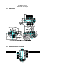
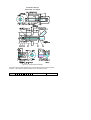
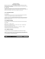
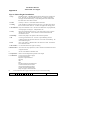
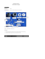
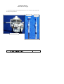
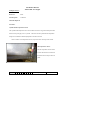
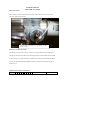
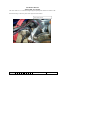
Installation Manual
Jabiru 3300 Aero Engine
INSTALLATION MANUAL
FOR
JABIRU 3300 AIRCRAFT ENGINE
This Manual has been prepared as a guide to correctly install the Jabiru 3300 engine
into an airframe.
Should you have any questions or doubts about the contents of this manual, please
contact Jabiru Aircraft Pty Ltd.
REVISION
0
1
2
3
4
H:\files\engine_manuals\3300_engine_manuals\Installation Manual 3300.doc
Dated : 22/08/03
Page: 1
Installation Manual
Jabiru 3300 Aero Engine
Table of Contents
1.0
DESCRIPTION ______________________________________________________ 4
2.0
SPECIFICATIONS ___________________________________________________ 4
3.0
DIMENSIONS _______________________________________________________ 5
4.0
DENOMINATION OF CYLINDERS_____________________________________ 5
5.0
ENGINE MOUNT ____________________________________________________ 6
6.0
CONTROLS _________________________________________________________ 8
6.1 Throttle and Choke _________________________________________________________ 8
6.2 Master Switch, Ignition Switches and Starter Button _____________________________ 8
7.0
INSTRUMENTS______________________________________________________ 8
7.1 Electronic Tachometer ______________________________________________________ 8
7.2 Oil Temperature Gauge _____________________________________________________ 8
7.3 Oil Pressure Gauge _________________________________________________________ 8
7.4 Cylinder Head Temperature Gauge ___________________________________________ 9
7.5 Exhaust Gas Temperature Gauge _____________________________________________ 9
8.0
ELECTRICAL EQUIPMENT__________________________________________ 11
8.1 Alternator ________________________________________________________________ 12
8.2 Regulator ________________________________________________________________ 12
8.3 Ignition __________________________________________________________________ 12
8.4 Starter Motor _____________________________________________________________ 13
8.5 Battery___________________________________________________________________ 13
8.6 Additional Wiring Information ______________________________________________ 13
9.0
FUEL SUPPLY SYSTEM _____________________________________________ 14
9.1 Fuel Tank ________________________________________________________________ 14
9.2 Fuel Filtration ____________________________________________________________ 14
9.3 Mechanical Fuel Pump _____________________________________________________ 14
9.4 Carburettor ______________________________________________________________ 14
9.5 Fuel Lines ________________________________________________________________ 15
10.0 AIR INTAKE SYSTEM _______________________________________________ 15
10.1 Air Filter ________________________________________________________________ 15
11.0 EXHAUST SYSTEM _________________________________________________ 15
REVISION
0
1
2
3
4
H:\files\engine_manuals\3300_engine_manuals\Installation Manual 3300.doc
Dated : 22/08/03
Page: 2
Installation Manual
Jabiru 3300 Aero Engine
12.0 COOLING SYSTEMS ________________________________________________ 15
13.0 PROPELLER SELECTION ___________________________________________ 16
14.0 AUXILIARY UNITS _________________________________________________ 16
Appendix A ______________________________________________________________ 16
Appendix B ______________________________________________________________ 19
LIST OF EFFECTIVE PAGES
The dates of issue for original & revised pages are:
Page
Issue
Date
1
2
3
4
5
6
7
8
9
10
11
12
13
14
15
16
17
18
19
1
1
1
1
1
1
1
1
1
1
1
1
1
1
1
1
1
1
1
09/03/99
09/03/99
09/03/99
09/03/99
09/03/99
09/03/99
09/03/99
09/03/99
09/03/99
09/03/99
09/03/99
09/03/99
09/03/99
09/03/99
09/03/99
09/03/99
09/03/99
09/03/99
09/03/99
REVISION
0
1
2
3
4
H:\files\engine_manuals\3300_engine_manuals\Installation Manual 3300.doc
Dated : 22/08/03
Page: 3
Installation Manual
Jabiru 3300 Aero Engine
1.0
-
4 Stroke
6 Cylinder Horizontally Opposed
1 Central Camshaft
Push Rods
Over Head Valves (OHV)
Ram Air Cooled
Wet Sump Lubrication
Direct Propeller Drive
Dual Transistorised Magneto Ignition
Integrated AC Generator
Electric Starter
Mechanical Fuel Pump
Naturally Aspirated – 1 Pressure Compensating Carburettor
8 Bearing Crankshaft
2.0
-
-
DESCRIPTION
SPECIFICATIONS
Displacement
Bore
Stroke
Compression Ratio
Direction of Rotation
of Prop Shaft
Ramp Weight
:
:
:
:
3314 cc
97.5 mm
74 mm
7.8:1 s/n 224 on is 8:1
:
:
Clockwise – Pilot’s view – Tractor Applications
81 kg (178 lbs) Complete including Exhaust,
Carburettor, Starter Motor, Alternator & Ignition
System.
25o BTDC
1–4–5–2–3–6
20 Amps
:
:
:
-
Ignition Timing
Firing Order
DC Output
Fuel Consumption
@ 75% Power
Fuel
-
Oil
:
-
Oil Capacity
Spark Plugs
:
:
REVISION
0
1
2
:
:
3
4
H:\files\engine_manuals\3300_engine_manuals\Installation Manual 3300.doc
24 l/hr (6 US gal/hr)
AVGAS 100LL and AVGAS 100/130
Leaded and Unleaded Motor Gasoline above
95 Octane Ron
Aero Oil W Multigrade 15W-50, or equivalent
Lubricant complying with MIL-L-22851C, or
Lycoming Spec. 301F, or Teledyne –
Continental Spec MHF-24B
3.5 L (3.69 US Quarts)
NGK D9EA – Automotive
Dated : 22/08/03
Page: 4
Installation Manual
Jabiru 3300 Aero Engine
3.0
DIMENSIONS
4.0
DENOMINATION OF CYLINDERS
REVISION
0
1
2
3
4
H:\files\engine_manuals\3300_engine_manuals\Installation Manual 3300.doc
Dated : 22/08/03
Page: 5
Installation Manual
Jabiru 3300 Aero Engine
Cylinder Firing Order: 1 – 4 – 5 – 2 – 3 – 6
5.0 ENGINE MOUNT
The design of the engine mount must not only take into account the structural
loadings but must make allowances for accessibility of components and the removal
of equipment located at the rear of the engine.
The engine has four engine mounting points located at the rear of the engine (refer
to figure 1.0) from which the engine is to be mounted. An optional bed mount may
be fitted.
Figure 1.0 – Engine Mount Point Locations
The correct installation is shown below in figure 2.0
REVISION
0
1
2
3
4
H:\files\engine_manuals\3300_engine_manuals\Installation Manual 3300.doc
Dated : 22/08/03
Page: 6
Installation Manual
Jabiru 3300 Aero Engine
Figure 2.0 – Engine Mount Assembly
Corrections of the engine alignment may be made using spacers under the rubber
cushions. The maximum spacer thickness on any one mount is 3mm.
REVISION
0
1
2
3
4
H:\files\engine_manuals\3300_engine_manuals\Installation Manual 3300.doc
Dated : 22/08/03
Page: 7
Installation Manual
Jabiru 3300 Aero Engine
6.0
CONTROLS
This section comprises of the mechanical controls and electrical switches.
6.1 Throttle and Choke
Provisions for the connection of the throttle and choke are made on the carburettor.
Note: Since a pressure compensating carburettor is used there is no mixture control.
6.2 Master Switch, Ignition Switches and Starter Button
The switches are connected as shown by the circuit diagram, on Page 10.
7.0
INSTRUMENTS
7.1 Electronic Tachometer
The tachometer uses a pick-up mounted on the alternator mounting bracket which
‘counts’ the teeth of the flywheel ring gear. Jabiru Part No. PI10772N is the
recommended tachometer.
On later engines tacho picks up on 2 metal tabs attached to the inside of the
flywheel. Pick up is of induction sender type.
Tachometer Wiring
3
Tachometer Negative (3) to Earth
4
Tachometer Positive (4) to Instrument
8
Tachometer to Red Wire tachometer pick-up
7
Tachometer to Black Wire tachometer pick-up
7.2 Oil Temperature Gauge
The Oil Temperature Gauge uses an electric probe mounted in the base of the
sump. Jabiru Part No. PI10752N is recommended.
Oil Temperature Wiring
Black Oil Temperature Gauge Negative to Earth
Red Oil Temperature Gauge Positive to Instrument
White Oil Temperature Gauge Sensor (S) to Oil Temperature Sensor
(Lower Left Eng Sump)
7.3 Oil Pressure Gauge
An electric oil pressure sender is fitted to the engine for an Oil Pressure Gauge.
Jabiru Part No. PI10762N is the recommended gauge.
Oil Pressure Wiring
Black Oil Pressure Gauge Negative to Earth
Red Oil Pressure Gauge Positive to Instrument
White Oil Pressure Gauge Sensor (S) to Oil Pressure Sensor (Fwd Top Eng)
REVISION
0
1
2
3
4
H:\files\engine_manuals\3300_engine_manuals\Installation Manual 3300.doc
Dated : 22/08/03
Page: 8
Installation Manual
Jabiru 3300 Aero Engine
7.4 Cylinder Head Temperature Gauge
The Cylinder Head Temperature Gauge uses a thermocouple. An audit must be
done to establish the hottest cylinder and the thermocouple probe should be fitted
under the exhaust spark plug on that cylinder. Jabiru Part No. PI10732N is the
recommended gauge.
Cylinder Head Temperature Wiring
Loom and sensor is supplied with the instrument. These must be installed as per
directions. If cable is too long it must be looped as many times as necessary and
strapped behind the instrument panel. Temperature of cold junction for best
results should be around 50º C. Ensure cold junction is furthest from the thermo
couple probe as possible.
DO NOT CUT TO LENGTH
Ensure that wire is not chaffing on the fibreglass air duct or cooing fins.
No power connection is required.
7.5 Exhaust Gas Temperature Gauge
An optional Exhaust Gas Temperature Gauge can be fitted. The probe should be
positioned 100mm from the port flange on the exhaust pipe of a convenient cylinder.
Jabiru Part No. PI0325N is the recommended gauge.
SCAT HOSE
Remove at each 50 hourly inspection one end of each scat hose. Inspect for holes,
leaks and condition of helical wound wire former. Replace if any signs of corrosion
is evident.
REVISION
0
1
2
3
4
H:\files\engine_manuals\3300_engine_manuals\Installation Manual 3300.doc
Dated : 22/08/03
Page: 9
Installation Manual
Jabiru 3300 Aero Engine
REVISION
0
1
2
3
4
H:\files\engine_manuals\3300_engine_manuals\Installation Manual 3300.doc
Dated : 22/08/03
Page: 10
Installation Manual
Jabiru 3300 Aero Engine
WARNING
PROBLEM –
Three Phase stator and regulator burning out.
WARNING –
Please note brown positive wire on regulator
must only carry a current when the engine is
running. The brown wire must be isolated
when the engine is not in use. Wiring
through master switch is O.K. if the engine is
started straight away. Problems will occur
when engine is not started straight away e.g.
someone carrying out ground testing of
radios and electrical equipment. If this is
carried out the brown wire will have to be
isolated or the regulator and stator will burn
out.
Note: Three phase units used on s/n 01 – 163. Single
Phase used from s/n 164 onwards.
REVISION
0
1
2
3
4
H:\files\engine_manuals\3300_engine_manuals\Installation Manual 3300.doc
Dated : 22/08/03
Page: 11
Installation Manual
Jabiru 3300 Aero Engine
8.0
ELECTRICAL EQUIPMENT
8.1 Alternator
The alternator fitted to the early Jabiru 3300 engines is a three phase, permanently
excited with a regulator. The rotor is mounted on the flywheel with the stator
mounted on the alternator mount plate at the back of the engine. The alternator
mount plate is also the mount for the ignition coils and the vacuum pump. Later
engines use a single phase alternator.
Specifications
Power (Max): 200W Continuous
Note: The electrical system is Negative Earth.
8.2 Regulator
The regulator has been selected to match the voltage and current of the integral
alternator. Only Jabiru Part No. PI12609N should be used. (The regulator output
voltage is 14 volts + 0.8 volt.) Single phase alternators use regulator part no:
PI10652N. Recommended wiring of regulator is positive and negative directly to
battery. A suitable fuse in series would be a recommendation.
8.3 Ignition
The ignition unit has dual breakerless transistorised ignition with the magnets
mounted on the flywheel and the coils mounted on the alternator mount plate.
The current from the coils flows to the distributor from where it is distributed to the
spark plugs. (See also Regulator Wiring at Page 12.)
The ignition is turned off by grounding the coils via the ignition switches.
The ignition is timed to 25o BTDC
The temperature limit for the ignition coils is 70oC. This should be checked by the
installer. It is recommended to fit a small pipe around ½inch (12mm dia) from the top
rear of the air duct and routed down to the coil to assist in cooling. Ignition coils
should be mounted on insulating washers.
Transistorised Ignition 1 Wiring
No. 1 Switch – Upper to Left Transistorised Ignition
No. 1 Switch – Lower to Earth
REVISION
0
1
2
3
4
H:\files\engine_manuals\3300_engine_manuals\Installation Manual 3300.doc
Dated : 22/08/03
Page: 12
Installation Manual
Jabiru 3300 Aero Engine
Switch Open for Ignition ON, closed for Ignition OFF.
Transistorised Ignition 2 Wiring
No. 2 Switch – Upper to Right Transistorised Ignition
No. 2 Switch – Lower to Earth
Switch Open for Ignition ON, closed for Ignition OFF.
8.4 Starter Motor
The starter is mounted on the top of the engine and drives the ring gear on the
flywheel. The motor is activated by engaging the starter button (the master switch
has to be ON) which trips the solenoid, hence current flows from the battery to the
motor. The cable from Battery to starter should be minimum 16mm2 copper.
Starter Wiring
Starter Button Switch (lower) to Main Bus
Starter Button Switch (upper) to Start Solenoid (through Grommet)
8.5 Battery
The battery should be of a light weight, 12V, 20 Ah type able to accept a charging
voltage up to 14 V (+ 0.8V) and a 25 AMP Input.
8.6 Additional Wiring Information
Engine Hourmeter Wiring
Red
Hourmeter Positive to Positive
Black
Oil Pressure Switch to Engine Sump Bolt
Black
Hourmeter to Oil Pressure Switch (Fwd Eng Left)
Earth Wiring
Black
Black
Battery Earth Negative to Firewall Earth (Engine Bay)
Battery Earth Negative to Earth Bus
Master Wiring
Red
Red
Red
Red
Starter Solenoid to Main Fuse
Main Fuse to Master Switch (Lower)
Master Switch (Upper) to Main Bus
Main Bus to Red on Regulator
Fuel Pump Wiring
Red
Main Bus to Fuel Pump Fuse
Red
Fuel Pump Fuse to Fuel Pump Switch (Lower)
REVISION
0
1
2
3
4
H:\files\engine_manuals\3300_engine_manuals\Installation Manual 3300.doc
Dated : 22/08/03
Page: 13
Installation Manual
Jabiru 3300 Aero Engine
Red
Black
Fuel Pump Switch (Upper) to fuel Pump (Red Wire)
Fuel Pump (Black Wire) to Earth Bus
Regulator
Red Regulator Wire to Battery
Brown Regulator Wire to Positive (only when ignition is on)
Black Regulator Wire to Earth
3 Yellow Regulator Wires to any 3 White Alternator Wires
Single Phase – 2 alternator wires to pale blue, red and yellow to positive bus and
black to negative bus.
Battery Cables
Black Starter Motor Mount (Engine Rear) to Battery Negative
Red Battery Positive to Starter Solenoid
Red Starter Solenoid (Switched) to Starter Motor (Part of)
9.0
FUEL SUPPLY SYSTEM
9.1 Fuel Tank
The fuel tank must be fitted with an outlet strainer of between 8 and 16 mesh per
inch, with a minimum total mesh area of 5 cm2.
9.2 Fuel Filtration
A Fuel filter capable of preventing the passage of particles larger than 0.1mm
(100um) must be installed between the fuel tank outlet and the fuel pump.
The filter must be present in the system for the fuel flow test. The size of the filter
should give consideration to allow adequate flow with a used filter.
A Ryco Z15 or similar filter has been used successfully.
9.3 Mechanical Fuel Pump
The mechanical fuel pump is mounted on the engine crankcase and is camshaft
driven. It is designed to supply fuel at the pressure described in the following
paragraph. To prevent fuel vaporization in the fuel pump a small amount of air
directed onto the pump is advised, especially when using mogas. Electric Boost
Pump must also be capable of no more than 3lb pressure.
9.4 Carburettor
A Bing constant depression type is used. This carburettor has a minimum delivery
pressure of 5 kPa (0.75 Psi) and a maximum pressure of 20 kPa (3 psi). To confirm
that the fuel system is capable of delivering this pressure a fuel flow test must be
performed. A method for performing a fuel flow test is available from Jabiru if
required. A drip deflector to deflect overflowing fuel from the exhaust system is
supplied as standard equipment on the engine.
REVISION
0
1
2
3
4
H:\files\engine_manuals\3300_engine_manuals\Installation Manual 3300.doc
Dated : 22/08/03
Page: 14
Installation Manual
Jabiru 3300 Aero Engine
Because the engine is dyno run some adjustment of the 7mm idle set screw may
have to be made. A hot idle of around 700 RPM is desirable. Earth strap from carby
to crankcase is recommended.
9.5 Fuel Lines
Fuel lines are nominally 6mm bore. All hoses forward of the firewall require fire
resistant sheathing and those between moving sections such as between engine and
firewall should be flexible. Hoses must be changed every two years.
10.0 AIR INTAKE SYSTEM
10.1 Air Filter
The air filter must be of a type so as to not cause positive RAM induction pressure.
The filter must be capable of supplying 250 kg/hr (550 pph) of air
The filter may have to be changed at regular intervals if the engine is to be used in a
dusty environment. Air flow should be as direct as possible, no tight bends and air
taken from outside the cowl.
11.0 EXHAUST SYSTEM
An exhaust system is provided with the engine. Both Pusher and Tractor systems
are available.
Muffler Volume – Capacity 5 litres
Back pressure at Takeoff Performance – Max 0.2 bar (2.9 psi) – readings taken
70mm from muffler flange connections.
Exhaust Gas Temperature (EGT) - Nominal 650o – 750o (1202oF – 1382oF)
measured 100mm from the exhaust manifold flange.
12.0 COOLING SYSTEMS
The engine should be installed using RAMAIR ducts provided with the engine.
Cylinder and cylinder head cooling is achieved by ducting air over the cylinders and
heads. The static air pressure inside the cooling ducts must not be lower than 4.3cm
(1.7”) water gauge at 1.3 times the stall speed.
REVISION
0
1
2
3
4
H:\files\engine_manuals\3300_engine_manuals\Installation Manual 3300.doc
Dated : 22/08/03
Page: 15
Installation Manual
Jabiru 3300 Aero Engine
An oil cooler should be installed and sized to achieve oil temperatures within the
engine limits. Hoses should be nominally 8mm (5/16”) bore. Hoses must be
changed every 2 years. Later coolers accept 3/8” diameter hoses.
The limits in the Specification Sheet, contained in Appendix B, must be strictly
adhered to. Warranty will not be paid on engine damage attributed to
overheating of cylinders or oil.
The cooling ducts provided are only a starting point in establishing effective engine
cooling. The ducts may require to be increased in size and additional baffles
provided to achieve the specified maximum cylinder head temperature of 175 oC.
Air ducts should have an air bleed hole of around 25mm in dia cut into the inside top
of each air duct and facing the crankcase. This provides air over the crankcase
region. The air ducts may need increasing in size and additional baffles depending
on installation. See head temperature range page 20.
13.0 PROPELLER SELECTION
The hub of the propeller must be drilled with holes to match the flange. The
propeller must be carefully selected to match the airframe and the engine.
Propellers up to 1778mm (70”) in diameter and between 762mm (30”) and 1397mm
(55”) in pitch may be used. The propeller flange is drilled with 6 5/8” holes at 4 3/8”
PCD.
Movements of inertia up to 0.3 kgm2
Applications outside this range should be referred to Jabiru.
14.0 AUXILIARY UNITS
Vacuum Pump
For the installation of an artificial horizon and/or a direction gyro a vacuum pump is
necessary. A Tempest 212CW (or equivalent) vacuum pump can be fitted to the
alternator mounting plate and directly coupled to the crankshaft. The drive pad is
dry.
The pad and spline are SAE Standard.
NOTE:
Unless operating in cool environments oil coolers are mandatory.
The adapter is fitted under the oil filter and can be plumbed
either way to the cooler. Continuous operation with oil
REVISION
0
1
2
3
4
H:\files\engine_manuals\3300_engine_manuals\Installation Manual 3300.doc
Dated : 22/08/03
Page: 16
Installation Manual
Jabiru 3300 Aero Engine
temperatures between 70 degrees and 90 degrees Celsius is
desirable.
REVISION
0
1
2
3
4
H:\files\engine_manuals\3300_engine_manuals\Installation Manual 3300.doc
Dated : 22/08/03
Page: 17
Installation Manual
Jabiru 3300 Aero Engine
Appendix A
REVISION
0
1
2
3
4
H:\files\engine_manuals\3300_engine_manuals\Installation Manual 3300.doc
Dated : 22/08/03
Page: 18
Installation Manual
Jabiru 3300 Aero Engine
Appendix B
SPECIFICATION SHEET
Models: Jabiru 3300
1. MANUFACTURER
Jabiru Aircraft Pty Ltd
P.O. Box 5186
Bundaberg West
Queensland 4670
2. ENGINE PARTICULARS
3.1
Description
Six cylinder, horizontally opposed, four stroke engine,
direct propeller drive, air cooled, wet sump, pressure
lubricated, dual magneto high voltage transistorised
contactless ignition, 1 x constant-pressure carburettor,
electric starter, generator, mechanical fuel pump. Vacuum
pump optional.
3.2
3.3
3.4
3.5
3.7
Displacement
Bore
Stroke
Compression Ratio
Net Dry Weight
3.8
Propeller Rotation Direction
3314 cm3
97.5 mm
74 mm
7.8 : 1 s/n 224 on is 8:1
81 kg (includes exhaust, starter, flywheel
alternator)
Clockwise (viewed from rear)
3. ENGINE PERFORMANCE
Static sea level ratings under the following conditions:(a) International Standard Atmospheric conditions at sea level.
(b) Aircraft service equipment drives unloaded. (Vacuum Pump not fitted)
(c) Full rich fuel/air mixture.
(d) Maximum cylinder head temperature.
(e) Standard Jabiru air filter and cold air.
(f) Standard exhaust muffler.
REVISION
0
1
2
3
4
H:\files\engine_manuals\3300_engine_manuals\Installation Manual 3300.doc
Dated : 22/08/03
Page: 19
Installation Manual
Jabiru 3300 Aero Engine
4.1 Engine Ratings
Maximum
120 HP / 3300 RPM ISO STD Conditions
5. OPERATING LIMITATIONS
5.1 RPM
Maximum
:
Recommended Cruise :
3300 RPM
2750 RPM
5.2 Engine Cooling
Cylinder Head Temperature
Takeoff
Continuous
175oC Maximum
150oC Maximum
5.3 Fuel
5.3.1 Specifications
Avgas 100LL & Avgas 100/130
Leaded and Unleaded Motor Gasoline above 95 Octane Ron
5.3.2 Pressure to Carburettor (above ambient)
(a) Maximum
(b) Minimum
20 kPa
5 kPa
WARNING – When using auto fuels, ensure all components of the fuel delivery system
are cooled to prevent fuel vaporization.
5.4 Oil
5.4.1
REVISION
Specification
Aero Oil W Multigrade 15W-50,
or equivalent Lubricant complying with
MIL-L-22851C, or
Lycoming Spec. 301F, or
Teledyne - Continental Spec MHF-24B
0
H:\files\engine_manuals\3300_engine_manuals\Installation Manual 3300.doc
Dated : 09/11/00
Page: 20
Installation Manual
Jabiru 3300 Aero Engine
5.4.2
Inlet Temperature
Minimum for Operation
Maximum
Continuous
5.4.3
Pressure
Normal Operations
Min
Max
Idle
Min
Starting & Warm Up Max
15oC
118oC
80oC – 100oC
220 kPa
525 kPa
80 kPa
525 kPa
6. TYPES OF PROPELLER
Fixed pitch wooden propellers.
Maximum propeller diameter 1778mm (70").
7. EQUIPMENT
(a) The following equipment is included in the engine approval:Carburettor:
1 x Bing constant Pressure carburettor Type 94/40
Main Jet 2.80, Needle Jet 280 (278)
Fuel Pump:
Mechanical, Jabiru part No: PG10332N
Ignition System:
Jabiru dual magneto, high voltage transistorised, contactless.
Part No: PI10522N
Spark Plugs:
NGK D9EA
Alternator:
Integrated Jabiru, permanent magnet three phase alternator or
single phase type.
Starter:
Jabiru 12V/1.0 kW, engagement via reduction gear and freewheel.
Bosch type part no: 4776093.
(b) The following optional equipment may be driven by or fitted to the engine subject to the
type number being included in the approved Jabiru Aircraft Pty Ltd engine specification:Vacuum Pump
REVISION
0
H:\files\engine_manuals\3300_engine_manuals\Installation Manual 3300.doc
Dated : 09/11/00
Page: 21
Installation Manual
Jabiru 3300 Aero Engine
Appendix C
Tips on Jabiru Engine Installations
1. Prop
Standard of 2800 – 2900 RPM at take off and 3200 in the air straight and
level. This will vary from aircraft and prop type. Variation from these
with prop lead will affect tuning. Carby tuning must not be altered other
than with advice from Jabiru Aircraft.
2. Tacho
Accuracy is obvious. Check with another instrument
3. Cooling
Cowls should have adequate entry and exit areas. Care taken not to flood
the cowl area with oil cooler air. Air ducts as supplied are starting points.
4. Air Induction Entry from outside the cowl. All scat hoses should have only slight bends,
no sharp edges on exiting air. Adequate filter size.
5. Carby
Bowl vent to filtered side of air box. Two sense holes on rear of venture
should not be obscured. Correct idle hot. Ensure throttle and choke
movement is correct.
6. Fuel Pump
Ensure boost pump is not capable of more than 3lb pressure.
7. Oil
Correct type used for first 25 – 30 hours. Expel inhibiting oil from
cylinders and pressure up before first start. Oil coolers are mandatory. Do
not overfill the engine.
8. Fuel
Only Avgas 100LL or MOGAS above 95 Octane to be used. Fuel filter in
line. Full tank vented.
9. Oil Overflow
Use of small collector for engine oil venting.
10. Heads/Valves
(See section on early operation 4.7) Valve clearance and head tension done
at regular intervals.
11.
No Oil or fuel additives should be used
12. Temperature
Refer to correct temperature operation of the engine
13. Connections
14.
REVISION
G on oil pressure sender to gauge
W is for warning light
Regulator as per instructions.
Oil temp
CHT
EGT
Fuel hoses/oil hoses with heat shield
Correct throttle/choke movement
Carby heat arrangement working
Correct scat hoses and directions
Sump vent pipe to collection bottle
Poor connections and air gaps to ducts/cooler etc give second rate cooling
0
H:\files\engine_manuals\3300_engine_manuals\Installation Manual 3300.doc
Dated : 09/11/00
Page: 21
Installation Manual
Jabiru 3300 Aero Engine
15.
Check for contact of engine to cowl.
16.
Damage caused by overheating due to poor installation techniques would not be
covered under warranty. Operation of the engine on non approved oils and
fuel will likewise not be covered.
17.
Overall performance of engine and airframe depends on correct installation and prop
match.
REVISION
0
H:\files\engine_manuals\3300_engine_manuals\Installation Manual 3300.doc
Dated : 09/11/00
Page: 21
Installation Manual
Jabiru 3300 Aero Engine
Typical Installation- 4/6 Cylinder Jabiru Engine
Reference:
Drawing
Photos
Parts Required:
Materials Required:
Please note: Prop Selection should aim to obtain 2800-2900 @ T/O & around 3200RPM full power
Straight & Level. Operation of the engine out side these Values may affect engine tuning.
• All Glass joins must have smoothed interiors.
•
Strongly recommend engines use air mixer box, adequate filter size, carby heat arrangement.
•
Note: Slope of air scat hose to carby & glass Joiner.
•
Important that scat hose not bunched up on carby. (no tight bends in scatt hose). Use a glass
joiner to prevent this and change direction.
Upper sensor holes on carby intake must not be covered by scat hose.
•
Air Inlet from
outside cowl
Keep cold junction of CHT Sender
away from heads
Air Induction
Air Ducts attached by front/back rocker cover cap screws
Oil Cooler
mounted on
rubber
grommets
Prop Torque on
wooden Jabiru prop
6 ½ -7Ft LB (9NM)
REVISION
0
1
2
3
4
H:\files\engine_manuals\3300_engine_manuals\Installation Manual 3300.doc
Print Date: 11/10/03 12:29 PM
Dated : 22 August 2003
Page: 1
Installation Manual
Jabiru 3300 Aero Engine
•
REVISION
0
1
Air Pipes to bleed air to both coils on each air duct.
2
3
4
H:\files\engine_manuals\3300_engine_manuals\Installation Manual 3300.doc
Print Date: 11/10/03 12:29 PM
Dated : 22 August 2003
Page: 2
Installation Manual
Jabiru 3300 Aero Engine
Connect Engine
Reference:
Photo
Parts Required:
Various – Refer to Packing List for this Section
Male Rubber
Engine mount
Female Rubber
Engine mount
Washer- Engine
mount Spacer
Washer- Engine mount
Air duct
Spring
Guide Bush Prop
Spring Mounting Bracket, Rivet & Washer
Lock wireRam Air
Cooling Ducts
Belleville
Washer
Exhaust Spring
Engine Accessory Pack
Bolts Required:
Engine – Engine Mount :- AN4-31a x 4
Procedure:
1. Attach Female Rubbers Engine mount to both engine attach point on the Top Only.
2. Attach Male Rubber Engine mount to lower engine mount pins.
REVISION
0
1
2
3
4
H:\files\engine_manuals\3300_engine_manuals\Installation Manual 3300.doc
Print Date: 11/10/03 12:29 PM
Dated : 22 August 2003
Page: 3
Installation Manual
Jabiru 3300 Aero Engine
3. With the Back of
the Aircraft
Washer- Engine
Supported & the
mount
wheels chocked,
lift the engine onto
Female Rubber
the engine mount.
Engine mount
4. Attaching the
lower engine
mount points first
by tilting the front
of the engine
Heat Proof Nut
down. Continue
Engine Backing Plate
raising the engine
& align the top
Male Rubber Engine mount
engine mount pins.
5. Insert the Male
Photo:Top of Engine attach mount points
Rubber engine
mount onto TOP
engine mount spigots followed by the Washer- Engine mount Spacer, Washer- Engine
mount, ¼” washer & Heat Proof nut. Refer to drawing.
6. Compress Rubbers by using a long deep reach socket inside in pin Engine mount & a GClamp with the swivel take off the Ball. See Photo.
REVISION
0
1
2
3
4
H:\files\engine_manuals\3300_engine_manuals\Installation Manual 3300.doc
Print Date: 11/10/03 12:29 PM
Dated : 22 August 2003
Page: 4
Installation Manual
Jabiru 3300 Aero Engine
Top Engine mount Rubber
Bottom Engine mount Rubber
7. Repeat same procedure for lower engine mount
rubbers except attach the Engine mount rubber male first. Refer to Drawing.
8. Tighten Nut until firm. (Engine mount Washer will compress until it touches Pin Engine
mount.)
REVISION
0
1
2
3
4
H:\files\engine_manuals\3300_engine_manuals\Installation Manual 3300.doc
Print Date: 11/10/03 12:29 PM
Dated : 22 August 2003
Page: 5
O
M
N
O
A
L
P
L
E
Page: 1
L
Dated : 22 August 2003
I
4
C
3
A
2
B
1
L
0
E
REVISION
H:\files\engine_manuals\3300_engine_manuals\Installation Manual 3300.doc
Print Date: 11/10/03 12:29 PM
B
U
P
A
C
P
I
P
L
E
P
R
P
A
E
O
N
W
G
I
E
N
R
E
E
M
N
O
G
U
I
N
N
T
E
C
Installation Manual
Jabiru 3300 Aero Engine
Installation Manual
Jabiru 3300 Aero Engine
Fuel Line Connected From Bulk
head to Fuel Pump.
9. Connect the fuel line to fuel pump.
Refer to photo). Make sure the
fireproof
Fuel Line from Fuel
Pump to Carby
Fuel Pump Breather
line to be vented
overboard.
sleeve is in place.
10. Make sure the Fuel Line from fuel pump to
the carburettor in connected.
11. Ensure that the fuel overflow line is in place, refer to photo, and secured to vent
overboard.
REVISION
0
1
2
3
4
H:\files\engine_manuals\3300_engine_manuals\Installation Manual 3300.doc
Print Date: 11/10/03 12:29 PM
Dated : 22 August 2003
Page: 2
Installation Manual
Jabiru 3300 Aero Engine
12. Fit the oil over flow bottle to the firewall by drilling and Riveting oil bottle holder in place
using 73as 6-6 rivets. Refer to photo
13. Connect the oil breather line.
Ensure that the oil overflow line is in place and vents overboard.
14. Fit Scat hoses
-
NACA duct to Air Inlet Housing Assembly.
-
Hot Air Muff to Carby Heat Inlet
Oil Breather
Lines
Oil Bottle
Oil Bottle
REVISION
0
1
2
3
4
H:\files\engine_manuals\3300_engine_manuals\Installation Manual 3300.doc
Print Date: 11/10/03 12:29 PM
Dated : 22 August 2003
Page: 3
Installation Manual
Jabiru 3300 Aero Engine
-
Air Inlet Housing Assembly to the Carburetor. (refer to photo )
Main Air
intake to
hotair mixer
box.
Scat hose
from hot-air
mixer box to
heat muff
onto exhaust.
REVISION
0
1
2
3
4
H:\files\engine_manuals\3300_engine_manuals\Installation Manual 3300.doc
Print Date: 11/10/03 12:29 PM
Dated : 22 August 2003
Page: 4
Installation Manual
Jabiru 3300 Aero Engine
15. Fit Carburetor cable to Carby making sure you use 2 x 5/16” washers on pin to align cable
& a split pin on opposite side.
Carby End
Throttle
Leaver End
Typical Throttle & Choke
REVISION
0
1
2
3
4
H:\files\engine_manuals\3300_engine_manuals\Installation Manual 3300.doc
Print Date: 11/10/03 12:29 PM
Dated : 22 August 2003
Page: 5
Installation Manual
Jabiru 3300 Aero Engine
Fit Engine Sensors
Reference:
Photo
Parts Required:
as detailed
Materials Required:
Procedure:
Cylinder Head Temperature Sensor
The cylinder head temperature sensor used in Jabiru aircraft is a J-type thermocouple located
under the rear spark plug of No: 6 cylinder. The VDO 310 980 Cylinder Head Temperature
Gauge Kit is installed as standard equipment in the Jabiru Aircraft.
Photo– Position of oil temperature sensor, oil pressure sensor and oil pressure switch
Oil Temperature Sensor
The Oil Temperature Sensor used is
a VDO 320 028 which is located in
the bottom of the sump as shown in
photo.
REVISION
0
1
2
3
4
H:\files\engine_manuals\3300_engine_manuals\Installation Manual 3300.doc
Print Date: 11/10/03 12:29 PM
Dated : 22 August 2003
Page: 6
Installation Manual
Jabiru 3300 Aero Engine
Oil Pressure Sensor
The oil pressure sensor is located at the base of the oil filter and this can be seen in photo.
The sensor used is VDO 360 001
Oil Pressure sender unit. Connect wire to “G” terminal. The “WK”
terminal is not used.
Exhaust Gas Temperature Probe
The exhaust gas probe used on Jabiru’s is a VDO 310 306 Pyrometer which is supplied as a
complete kit. The probe is mounted in an exhaust pipe and as such the mount must be welded
on, (this fitting is not standard) and this is best done at the time of order although the exhaust
pipe may be returned and the fitting added it may take a couple of weeks before the pipe is
returned to you.
Magnetic Pick-up Sensor (Tachometer)
REVISION
0
1
2
3
4
H:\files\engine_manuals\3300_engine_manuals\Installation Manual 3300.doc
Print Date: 11/10/03 12:29 PM
Dated : 22 August 2003
Page: 7
Installation Manual
Jabiru 3300 Aero Engine
The sensor used is a 6.35 x 22 mm analogue magnetic pick-up and is fitted to a bracket on the
alternator housing as shown in photo in the engine electrical section.
Tacho sender location
REVISION
0
1
2
3
4
H:\files\engine_manuals\3300_engine_manuals\Installation Manual 3300.doc
Print Date: 11/10/03 12:29 PM
Dated : 22 August 2003
Page: 8