1
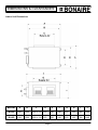
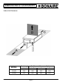
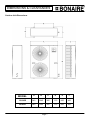
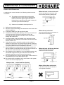
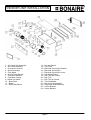
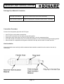
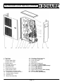
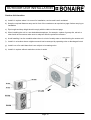
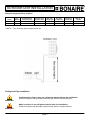
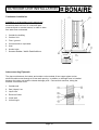
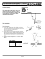
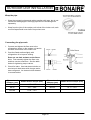
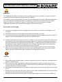
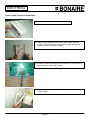
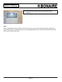
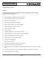
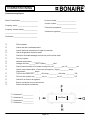
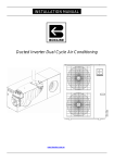
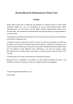
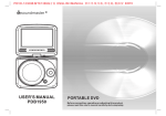
INSTALLATION MANUAL
Ducted Inverter Reverse Cycle Air Conditioning
With the
Classic Wall Mounted Controller
& IR Remote
www.bonaire.com.au
Page 1
CONTENTS
INTRODUCTION .............................................................................................................................3
General ................................................................................................................................ 3
Warning................................................................................................................................ 3
Precaution ............................................................................................................................ 3
DIMENSIONS & CLEARANCES.....................................................................................................5
Indoor Unit Dimensions ........................................................................................................ 5
Indoor Unit Clearances......................................................................................................... 6
Outdoor Unit Dimensions ..................................................................................................... 7
Outdoor Unit Clearances...................................................................................................... 8
NDOOR UNIT INSTALLATION .......................................................................................................9
Indoor Unit Location ........................................................................................................... 10
Notes for installation .............................................................................................. 11
1. Installation for the Indoor Unit.......................................................................... 11
2. Floor or Platform Mounting .............................................................................. 12
3. Levelling the unit.............................................................................................. 12
4. Ducting and fittings. .......................................................................................... 12
5. Drainage Pipe Installation ................................................................................. 13
Drainage Pipe Material & Insulation ................................................................................... 14
Connection Procedure........................................................................................................ 14
Heat Insulation ................................................................................................................... 14
OUTDOOR UNIT INSTALLATION ................................................................................................15
Outdoor Unit Location ........................................................................................................ 16
**NOTE – The minimum pipe length must be 5m............................................................... 17
Refrigerant Pipe Installation ............................................................................................... 17
Condenser Installation........................................................................................................ 18
Interconnecting Pipework ................................................................................................... 18
Suction Trapping ................................................................................................................ 19
Pipe Installation.................................................................................................................. 19
Flare Preparation ................................................................................................... 19
Wrap the pipe..................................................................................................................... 20
Connecting the pipe work................................................................................................... 20
Evacuation and Charging ................................................................................................... 21
Additional Charge............................................................................................................... 22
ELECTRICAL ................................................................................................................................23
Warnings ............................................................................................................................ 23
Other Precautions.................................................................................................. 23
Wiring Diagram .................................................................................................................. 24
Wiring Method for the Indoor Unit ...................................................................................... 25
Wiring Method for the Outdoor Unit.................................................................................... 25
Classic Wall Controller Installation ..................................................................................... 26
COMMISSIONING .........................................................................................................................28
Commissioning of the unit .................................................................................................. 28
Warning ................................................................................................................. 28
NOTES ..........................................................................................................................................30
Page 2
INTRODUCTION
INTRODUCTION
General
Bonaire Reverse Cycle Ducted Inverter air conditioners include two separate units – An Indoor and an
Outdoor Unit. The two units are interconnected by two refrigerant pipes and electric cables. Unit functions
are controlled by a hard wired low voltage controller and an auxiliary Infra Red Remote controller
Warning
The air conditioner must be installed by an authorised, licensed installer, according to Climate
Technologies specifications and using recommended standard refrigeration grade copper, electrical cables
and correct installation tools. Failure to comply with the above may void warranty!
Precaution
•
•
Read the following “PRECAUTIONS” carefully before installing.
The warning and caution items stated here must be followed as these important notes are related to
safety. The definition of warnings and cautions used in this table below. Incorrect installation due to
ignoring these instructions will cause harm and/or damage. The seriousness is classified by the
following indications
This indication shows the possibility of causing death or serious injury
WARNING
This indication shows the possibility of causing injury or damage to properties only.
CAUTION
NOTE:
1. Injury means causing harm, burns, electrical shock, which are not serious for hospitalisation.
2. Damage of property means that property has been rendered irreparable
Page 3
INTRODUCTION
WARNING
•
Only a licensed, qualified and trained specialist installer should be used to install this equipment.
Installation performed by unqualified persons will potentially cause water leakage, electrical shock or
fire
•
Install strictly according to these installation instructions. If the installation is does not comply with these
installation instructions, it will potentially cause water leakage, electrical shock or fire
•
Use the attached accessories and specified parts for installation. Otherwise, it will potentially cause
water leakage, fire, electrical shock or the unit to fail.
•
Install in the correct location which is able to withstand the unit’s weight. If the strength of the
structure isn’t enough or the installation isn’t properly executed, the unit may fall and cause injury
•
For all electrical work, follow local, state & national wiring standards, regulations and these installation
instructions. An independent circuit must be used. If the electrical circuit capacity is too small or a
defect in the electrical work is present, it may cause an electrical shock or fire.
•
When carrying out the piping connections, take care not to let air or other non condensable matter
into the refrigeration circuit. Only the specified refrigerant should go into the refrigeration circuit.
otherwise it may cause a lower capacity, abnormal high pressure in the refrigeration system causing
component or a complete system failure, errors and/or injury.
•
Grounding is necessary. It may cause electrical shock if grounding is not correct.
•
Do not install the unit in a place where leakage of flammable gas may occur. If gas leaks and
accumulates, it may cause a fire
Text and Illustration Copyright Climate Technologies 2010
All rights reserved. No part of this document may be reproduced or transmitted in any form or by any means,
electronic or mechanical, including photocopying, recording or by any information storage and retrieval system,
without prior permission in writing from Climate Technologies
In the interest of continued product improvement Climate Technologies reserves the right to alter specifications
without notice. E.&O.E
Page 4
DIMENSIONS & CLEARANCES
DIMENSION S & C LEAR ANC ES
Indoor Unit Dimensions
MODEL
A
B
BI12ID
1243
1200
BI14ID
1243
1200
C
D
E
F
G
H
I
J
1096 x 310 550
590
640
850
222
380
1340
1096 x 310 550
590
640
850
222
380
1340
Page 5
DIMENSIONS & CLEARANCES
Indoor Unit Clearances
MODEL
(Mandatory)
Fan Removal Clearances Options
A
A+B
C
D
BI12ID
500
500
500
450
BI14ID
500
850
850
450
Page 6
DIMENSIONS & CLEARANCES
Outdoor Unit Dimensions
MODEL
A
B
C
D
E
F
BI12OD
940
1245
365
375
600
400
BI14OD
940
1245
365
375
600
400
Page 7
DIMENSIONS & CLEARANCES
Outdoor Unit Clearances
In selecting the correct location, the following criteria must be
considered:
a)
The outdoor unit and the indoor unit must be
installed as close to each other as possible and
requires a minimum pipe length of 5 meters. If
longer tubing is required see the table on page 21
or consult your technical sales rep.
b)
Outdoor unit installation should provide for:
When the back is close to the wall
The top and the front need to be open.
This includes protruding window sills.
1500mm
1. Safe and easy service access.
2. Minimum noise and discharge air disturbance to the owner and
nearby neighbours.
3. A minimum distance of 100 mm from the wall
4. If installed in a closed place (balcony, attic, etc), an outdoor air
vent large enough to remove all discharge air from the
condenser and must prevent hot/cold air from recirculation
through the outdoor unit.
5. If several outdoor units are installed in the same area, make
sure that the hot air outlet from one outdoor unit does not enter
another outdoor unit.
6. Verify that any wall on which the outdoor unit is installed is
capable of carrying the unit’s weight and prevention measures
for noise transfer into the building is undertaken. Do not install
on a light unstable structure susceptible to vibration.
7. When installing on a balcony above the first floor, make sure
that the outdoor unit location allows easy access for removal of
the top cover and/or the entire unit, if necessary.
8. If the outdoor unit is installed in a non-accessible location, long
and flexible refrigerant tubing and electrical cable must be
installed to allow the unit to be moved for servicing.
9. Do not install the unit in a highly polluted area in which the air is
contaminated by oil, mist, salt or sulfuric gas.
When the top is blocked
The front and the sides must be clear for
these minimum clearances.
When the back & sides are blocked
The back and the side minimum
clearances must be achieved
10. Do not alcove the condensing unit in an manner or the system
will run at a reduced capacity or fail
Multiple Units – Lateral and Rear Spacing
When all the sides are blocked
If all sides are blocked, this will be an
unacceptable installation
Page 8
INDOOR UNIT INSTALLATION
NDOOR UN IT IN ST ALL AT ION
1 – Air Outlet Sub-Assembly
2 – Air Outlet Assembly
3 – Circular Air Director
4 – Scroll Assembly
5 – Fan Wheel
6 – Scroll Fixing Bracket
7 – Fan Motor Bracket
8 – Fan Motor Clamp
9 –Indoor Fan Motor
10 – Base Plate
11 – Beam
12 – Right Side Barrier
13 – Left side Barrier
14 – Top Cover
15 – Electrical Control Box Bracket
16 – Electrical Control Box
17 – Electrical Control Box Cover
18 – Pipe Board Fixture
19 – Drip Tray Bar Fixture
20 – Drip Tray
21 – Drip Tray Air Guard
22 – Top Crossbeam
23 – Left Corner Knighthead
24 – Evaporator Sub-Assembly
25 – Corner Bracket
26 – Centre Bracket
Page 9
INDOOR UNIT INSTALLATION
CAUTION
This unit must be installed by a licensed, qualified and trained installer. Installation by
unqualified persons may result in normal operations not being correctly checked, personal
safety may be compromised, property damage may be sustained and the unit may be
damaged. The warranty may also be void if qualified persons are not used to install the
system.
Indoor Unit Location
The indoor unit is designed for installation within a ceiling/roof space or other compartment, where there is
no influence from outdoor elements.
While selecting the location, the following conditions must be assured:
a) The location should assure free flow of the return air into the unit without interference.
b) The unit should be located central to allow for even air flow and distribution to rooms.
c) Avoid obstacles which may restrict the return air intake or the discharge supply air flow.
d) The unit should not be installed close to rooms where operational noise may cause concerns
(bedrooms, children rooms, etc).
e) If installing the unit on a platform, ensure that the structure is capable of supporting the indoor unit and
platform.
NOTE: The indoor unit should not be installed outside.
Page 10
INDOOR UNIT INSTALLATION
Notes for installation
•
Flexible ducting used should conform to the Australian standards for insulation resistance
relative to this product.
•
The return-air duct should be as short as possible, with full acoustic lining. The duct diameter
should be of a size correct for the installation requirements to minimise the static pressure
losses.
Design and prepare in advance easy access for servicing as follows:
•
The minimum height clearance for the installation is 410 mm.
•
Allow for access to the electrical control box to facilitate its easy removal by opening the
cover (fastened by 4 screws).
•
A distance of 500mm must be kept to allow access to the electrical service panel. For the
maintenance of fan wheels and motor see the indoor unit clearances. See Page 6.
1.
Installation for the Indoor Unit
•
Installation of the indoor unit must ensure a minimum length of refrigeration pipe work and ducting is
used, therefore the Indoor unit should be installed at a reasonable distance from the Outdoor unit.
Minimum Pipe Length: 5 meters
Maximum Pipe Length: 25 meters
Suspension Installation
•
Ensure adequate strength of the building structure so as to withstand the weight of the unit.
•
Determine the position of the suspension rod, align it to the suspension-mounting hole in the unit, and
then tighten it (for the position of the suspension rod, see the outline dimensional drawing of the unit)
Suspension Mounting into concrete slab
•
If the ceiling is old, use anchor bolts. For the newly-built ceiling, use an embedded fixed plate or
embedded anchor bolts or other locally purchased parts to reinforce the ceiling, ensure that the
concrete is hard enough to support the weight of the indoor unit.
Page 11
INDOOR UNIT INSTALLATION
2. Floor or Platform Mounting
•
Create a platform using bearers and chipboard.
Place the unit platform over load bearing walls or
on strategically located trusses in the roof space.
•
Place serrated rubber pads or isolating springs
under each corner of the unit to minimize /
eliminate any noise transmission.
3. Levelling the unit
•
Adjust the level of the unit as required. The drainpipe end
of the unit must be lower by at least 5mm for good
drainage.
•
Take care not to damage the drain tubes or coil when
lifting to adjust unit level
•
For suspension mounting units, tighten the locking nuts
once the revised position is determined.
4. Ducting and fittings.
•
Do not place an outlet register near the controller/thermostat as this can cause false readings
•
Do not place registers so that air is blown over people e.g. above beds or couches
•
To avoid exceeding maximum allowable air pressure drop in ducted system, do not use excessive
lengths of duct. If a duct run exceeds 6 meters always install the next size larger ductwork.
•
Flexible ductwork must be run as straight as possible between the indoor unit and the supply air
registers.
•
The airflow through each outlet must be individually set to air
balance the system.
•
All ductwork should be streamlined avoiding sharp angles that will
reduce airflow.
•
Ensure all ductwork is taped airtight so that there is no leakage.
•
Balancing dampers maybe required to ensure even air distribution.
•
Always install damper blades in the branch take off fittings.
•
Ensure that the final ductwork bend to each ceiling register is a smooth radius so that the
airflow has an even bend from the register into the room. The minimum radius bend is 1.5
times the duct diameter.
•
Do not squash ductwork to fit through an opening, as airflow will be restricted. Find a better
location.
•
Duct work needs to be supported through its entire length to prevent air flow restrictions.
•
The supply air transition is to be a tapered transition.
Page 12
INDOOR UNIT INSTALLATION
5. Drainage Pipe Installation
CAUTION
•
•
•
•
•
Be sure to follow this Installation Manual during the drainage installation. The
drainage pipe must have the heat insulation to prevent condensing
The drain pipe of the indoor unit must have heat insulation on it, or it will condensate, as well as the
refrigeration connections of the indoor unit.
The fall of the drain pipe should not be over 1/100, with no dipping and bending.
The total length of the drain pipe when pulled out straight shall not exceed 20m, when the pipe is over
this length, a prop stand must be installed every 1.5 to 2m to prevent dipping.
Refer to the following pictures about the installation of the drain pipes.
Do not impose any pressure on the connection part of the drainage pipe.
BE SURE THAT A “P” TRAP IS
PRESENT IN THE MAIN
DRAIN. FAILURE TO DO SO
MAY RESULT IN PROPERTY
AND EQUIPMENT DAMAGE.
Page 13
INDOOR UNIT INSTALLATION
Drainage Pipe Material & Insulation
Drainage Pipe Material
Polyvinyl Chloride Pipe (Ø32 Outer Diameter)
Heat Insulation Material
Foamed Polyethylene Insulation Plate (10mm Thickness)
Connection Procedure
Connect the transparent pipe with the PVC pipe.
•
•
•
•
•
Use PVC glue on the drain connections.
Prime both connections of the drain to be glued together
Paste glue at the front 40mm of the PVC pipe and insert it into the transparent pipe.
PVC Glue needs 10 minutes to dry. Do not impose pressure on the connection during the drying period.
After the drain is completed and all glued connections are dry test the drain for leaks and flow.
Heat Insulation
Wrap the flexible hose carefully with the attached heat insulation material from the start to the end (to
indoor part)
Page 14
OUTDOOR UNIT INSTALLATION
OUTDOOR UNIT IN STALLATION
1- Top Cover
2 - IPM PCB
- Outdoor Main PCB
- Outdoor PFC PCB
3- Outdoor Motor
4 – Four-way valve coil
5 – Four-way Valve
6 – Electrical Valve
7 – High Pressure Valve
8 – Low Pressure Valve
9 – Compressor DA150S1C-20FZ
10 – Compressor PA290X3CS-4MU1
11 – Outdoor Motor Support
12 – Outdoor Fan
13 – Base Sub-Assembly
14 – Condenser Sub-Assembly
15 – Front Right Clapboard
16 – Front Left Plate
17 – Big Handle
18 – Back Right Clapboard
19 – Fan Capacitor (Not Shown)
20 – Compressor Capacitor (Not Shown)
21 – Sensor (Not Shown)
22 – Sensor (Not Shown)
23 – High Pressure Switch (Not Shown)
24 – Reactor (Not Shown)
25 – AC Contactor (Not Shown)
Page 15
OUTDOOR UNIT INSTALLATION
Outdoor Unit Location
a) Install it in a place where it is correct for installation, service and is well ventilated.
b) Keep the required distance away and in front of the condenser as required on page 8 when carrying on
installation
c) Pipe length and drop height should comply with the table on the next page
d) When installing the unit in a non desirable atmosphere, for example, a place of greasy dirt, salt air or
other harsh environments make sure to adopt an effective protection measure.
e) Avoid installing it on the roadside where there is a risk of muddy water or dust blocking the outdoor coil.
f)
Install it in a location where neighbours would not be annoyed by operating noise or discharged hot air
g) Install it on a firm solid base that is not subject to increasing noise
h) Install it in a place without restrictions to the air outlet
Page 16
OUTDOOR UNIT INSTALLATION
Allowed Length and Drop of Pipes
Model
Pipe
Material
Liquid Side Pipe
diameter (mm)
Gas Side Pipe
diameter (mm)
Max Pipe
Length (m)
Min Pipe
Length (m)
Max Drop
Height (m)
Max No. of
Bends
BI12ID/OD
Copper
Ø9.52
Ø19.05
25
5**
7.5
5
BI14ID/OD
Copper
Ø9.52
Ø19.05
25
5**
9
5
**NOTE – The minimum pipe length must be 5m
Refrigerant Pipe Installation
Ventilate the air if there was any refrigerant leakage during the installation.
Leaked refrigerant will generate poisonous gas when in contact with fire.
WARNING
Make sure there is no refrigerant leakage after the installation.
Leaked refrigerant will generate poisonous gas when in contact with fire.
WARNING
Page 17
OUTDOOR UNIT INSTALLATION
Condenser Installation
Installation on a flat surface (roof, ground, etc)
Install the outdoor unit, support it in a position
elevated at least 100 mm on a concrete pad,
concrete block or wooden beams, in order to allow
free water flow underneath.
1. Outside the building
2. Outdoor Unit
3. Floor / ground
4. Concrete slab or equivalent
5. Wall
6. Anchor bolts
7. Serrated Rubber / Waffle Pad 40x80 mm
Interconnecting Pipework
The pipe work between the indoor and outdoor units consists of two copper pipes and an
electrical cable routed through a 60-mm wall opening. In addition, a drainage hose is installed
between the indoor unit and the closest drainage point. Connect both sections, taking the
shortest, most direct route.
1. Outside wall
2. Gas (Vapor) Line
3. Liquid Line
4. Electrical Cable
5. Inside wall
6. Incline Angle
Page 18
OUTDOOR UNIT INSTALLATION
Suction Trapping
If the outdoor unit is installed above the indoor
unit a suction trap (oil trap) must be fitted at the
lowest point of the riser. The radius of this trap
must be as short as possible. An additional trap
is to be fitted every 4 meters of rise that the
refrigeration pipe work travels.
Pipe Installation
Flare Preparation
a) Cut the pipe, using a pipe cutter. Make sure that the
cut is perpendicular to the pipe axis. Ensure the pipe is
de-burred and free of metal shavings
Do not use a hacksaw
b) Slip the flare-nut over the pipe, secure the pipe in the
flaring tool and perform the flare on the pipe end. The
pipe projection length (A) from the flaring block varies
with pipe diameter and shall be set as indicated in the
table.
c) Apply few drops of refrigeration oil to the tube before
flaring.
Flare Depth (A)
A (mm)
PIPE OD
1.3
9.58mm (⅜”)
1.9
15.88mm (⅝”)
2.1
19.05mm (¾”)
1. Copper Pipe
2. Flaring Tool
Page 19
OUTDOOR UNIT INSTALLATION
Wrap the pipe
•
Wrap the connecting pipes and cables together with tape, but do not
include the drainage pipe. Drainage pipe can be fixed along them
separately.
•
Wrap from the joint of the outdoor unit to that of the indoor unit; each
round of tape should cover half of its previous one.
Connecting the pipe work
1. Connect and tighten the flare nuts to the
refrigeration valves on the outdoor unit and to
the male connectors of the indoor unit.
2. Coat the flared surfaces lightly with
refrigeration oil to improve sealing.
Does not use leak sealants on the flares.
Note: First manually tighten the flare nuts,
and then use two wrenches. See the table
below for tightening torque values.
3. Check for leaks. Use leak detect solution or
an electronic leak tester with nitrogen and a
trace refrigerant. An electronic leak detector
is recommended.
Pipe external
diameter (mm)
Added wrench torque (N.m)
Pipe external
diameter (mm)
Added wrench torque (N.m)
Ø6.35
13.7 ~ 16.7
Ø12.7
49.4 ~ 60.4
Ø9.52
32.7 ~ 39.9
Ø19.05
97.1 ~ 118.7
Ø15.88
61.8 ~ 75.5
Page 20
OUTDOOR UNIT INSTALLATION
WARNING
This paragraph describes the necessary steps for setting up the unit for operation. Be sure to follow the
instructions, to assure proper functioning of the air conditioner.
The outdoor unit is pre-charged with the correct amount of refrigerant for 5 meters. Extended refrigeration
pipe runs, additional refrigerant will need to be added at 100 grams per meter above the pre-charged
length, (for pipe runs in excess of 5 meters). This process must only be performed by qualified
refrigeration technicians with a professional charging set and vacuum pump.
Evacuation and Charging
a) Connect two charging hoses from the gauge set to the outdoor unit as shown in the diagram on the
next page.
b) Connect the centre hose of the gauge set to a vacuum pump and a vacc stat.
c) Turn on the vacuum pump and make sure that the low pressure gauge reading moves from 0 KPA to a
negative. Vacc the system down until the vacc stat reads 500 micron.
d) If gauge needle does not move from 0 KPA to a negative, or the vacc stat wont pull down to 500 micron
this indicates a leak. Take the following measures: tighten all connections; if leaking stops when the
pipe work connections are tightened, proceed from step c. If leaking persists even after connections
are tightened, nitrogen charge the refrigeration lines and detect the leak, repair it then proceed from
step c; be sure to proceed only after all leaks have been eliminated.
e) Close the valves of both the gas and liquid sides of the charging set and turn off the vacuum pump.
Make sure that the gauge needle does not move or the vacc stat start to rise for 5 minutes. If either
starts to rise this could indicate a leak or moisture in the refrigeration pipe work.
Cautions
f)
When performing the following steps, avoid any exposure to the service valve ports; remember that the
system is under pressure.
g) Remove the valve caps from the service valves. Starting with the liquid line position both valves to
“open” using a 5mm Hex/Allen key wrench. Open each valve by rotating the centre spindle in an anticlockwise direction until fully back seated.
h) Disconnect the charging hoses from the vacuum pump and from the service ports of both the three-way
valves.
i)
Replace the service port and valve caps of both tree-way valves and tighten them with a torque wrench;
see table of torque values listed on the previous page.
j)
Replace valve caps of both service valves. Check for gas leakage with a leak detector or bubble up.
Page 21
OUTDOOR UNIT INSTALLATION
1.
Charging Set
2.
Vacuum Pump
3.
Outdoor Unit
4.
Service Port
5.
Valve Cap
6.
3-Way Gas Valve
7.
3-Way Liquid Valve
8.
Valve Cap
9.
Liquid Flare Connection
10.
Gas Flare Connection
11.
Indoor Unit
Additional Charge
1) Add 100 grams per meter of 9.53 (3/8”) liquid line over and above the specified system precharged length. See the unit name plate for this information. DO NOT exceed the maximum
equivalent pipe length on each unit.
2) Service port on the liquid service valve is not supplied on all units.
1. Valve Protection Plug
2. Insert 5mm Hex / Allen key to open/close
the Refrigerant Valve
3. Valve Protection Cap
4. Refrigerant Valve
5. Service Port cap
6. Flare Nut
7. Valve Mounting Bracket
8. Copper Tube
Page 22
ELECTRICAL
ELECTRIC AL
Warnings
•
Supply cables and interconnecting cables should be sized according to AS3008.1 and maximum
current of the unit.
•
Do not apply any pressure on the terminals used for connection. Improper connection may cause fire.
•
Grounding must be properly done. The grounding wire should be away from gas pipes, water pipes,
telephone, lightening rods or other grounding wires. Improper grounding may cause electric shock.
•
Electric Wiring must be done by a qualified electrician.
•
Use a separate circuit according to national regulations.
•
The temperature of the refrigerant circuit will be high, please keep the interconnecting cables away
from the refrigeration pipes.
•
If the wiring capacity is not enough, electric shock or fire may occur. An all-pole disconnection switch
having a contact separation of at least 3mm in all poles should be used.
Other Precautions
Be sure to install the correct sized circuit breaker or nuisance tripping or a fire may occur.
•
•
•
•
•
•
•
The supply cable is to be selected according to national and local regulations.
The outdoor unit power cable should be selected and connected according to the outdoor
unit installation manual, local and national regulations.
Wiring should be away from high temperature components, or the insulation layer of the
cables may be damaged.
Use cable clamps provided in the units to fix the cables in position after connection.
The control cable should be wrapped together with the heat insulated refrigerant pipes.
Connect the indoor unit to the power only after the refrigeration pipe work has been
vacuumed and charged.
Do not connect the power wire to the signal wire connection terminals or damage may occur.
Important Notes
1. Refer to AS3008.1 for the sizing of the supply cable for the unit.
2. Refer to AS 3008.1 for voltage drop calculations and values to avoid voltage drop.
3. The cross section of ground wire for the entire set of air conditioners should be 2.5mm² at least.
4. Multi stranded cables with an insulation rating of at least V90 250V should be used.
Page 23
ELECTRICAL
Wiring Diagram
Page 24
ELECTRICAL
Wiring Method for the Indoor Unit
Wiring method for indoor unit: Open the electrical control box to carry out the wire connections. Notice that
the connecting wire should be passed through the wire inlet rubber grommet on the box. Connect the wires
according to the stipulations on the wiring diagrams. The wire splices at the end of the terminals should be
tightly compacted. Wiring should not be loosely connected.
Wiring Method for the Outdoor Unit
1. Install a dedicated circuit from the mains switch board.
Circuit breaker requirements as per table below.
2. Connect the mains cables to the incoming connection block
on the outdoor unit
3. Connect the low voltage control cable from the indoor unit
to the comms port available on the outdoor PCB.
Use supply wire sizes as per local electrical codes and regulations.
Required Circuit
Breaker Size
Full Load
Amps
BI12ID/OD
32A
26.6A
BI14ID/OD
40A
30A
Model
Electrical Control Box
Please Note: Cable sizes are subject to length of cable run and full load amps calculated via
AS 3008.1
Page 25
ELECTRICAL
Classic Wall Controller Installation
1) Detach the rear cover of wall controller.
2) Before fixing the back cover on the wall, ensure that the
length of the LCD display wiring which will go through the
back cover will be at least 100mm.
3) Install four wires according to the directions on the back cover
then screw down the fixing screws;
4) Test communications and then fix the wall controller to the
backing plate
Page 26
ELECTRICAL
5) Ensure the wall controller can be used properly after
installation.
Note:
Before installing the wall controller for the indoor unit, the user must shut down the power supply of the
indoor and outdoor unit first, and then pull out the display PCB from the main PCB, and then connect the
wall controller to the main PCB.
Page 27
COMMISSIONING
TROUBLESHOOTING
COMMISSIONING
Commissioning of the unit
Warning
The unit’s sump heater must be energised for at least 12 hours prior to start up of the
compressor or failure may occur.
□
□
□
□
□
□
□
□
□
□
□
□
□
□
□
□
□
□
□
Ensure all electrical terminals and connections are tight.
Ensure fan blades and wheels are tight and spin freely.
Ensure service valves are open.
Leak test refrigeration pipe work connections.
Drain and safety tray drain are connected and tested.
Check all ducting is connected and air tight
Ensure return air filter is fitted.
Power up the unit.
Test supply voltage is correct at the main terminal strip.
Test run the system in all modes (Heating, Cooling and Ventilation)
Check air flow to all outlets are balanced as required.
Test all sundry items (such as damper motors).
Fill in the commissioning report.
Refit all covers to the units
Demonstrate the operation of the system to the customer.
Explain to the customer the cleaning of the filters.
Explain that the air conditioning system requires preventative maintenance and how often it should be
done.
Give the commissioning report, owner’s manual and certificates of compliance to the customer.
Ensure the site is cleaned of all rubbish.
Page 28
COMMISSIONING
Commissioning Report
License number _____________________
Date of commission ___________________
Invoice number _____________________
Company name ______________________
Technician’s signature ________________
Company contact details_______________
Customer’s signature _________________
___________________________________
Technician _________________________
□
□
□
□
□
□
□
□
□
□
Filter installed.
□
□
□
□
□
T/D over the indoor coil. _______ R/A temp _________ S/A temp _________ T/D.
Check and test condensate drain.
Check electrical connections for tight connections.
Check refrigeration flares for leaks.
Check for fan blade damage and security on the motor shaft.
Test run system.
Ambient temperature ___________
Voltage. No load _______VAC. Loaded ________VAC.
Check pressures after 15 minutes running time. HP ________ psi, LP_________ psi.
Check current draws after 15 minutes running time. Supply _________ Amps.
Compressor __________Amps.
T/D over the outdoor coil. _______ Air on. __________ Air off. ____________ T/D.
Check for air flow to all registers.
Ensure condenser is level and secure.
Record condenser clearances
□
□
□
□
Clearance F ___________
Air Flow
Clearance G ___________
Clearance H ___________
Clearance I ____________
Page 29
NOTES
NOTES
Page 30
NOTES
Page 31
WARRANTY
Manufactured by
Climate Technologies
ABN 13 001 418 042
26 Nylex Avenue
Salisbury, SA 5108
Australia
www.bonaire.com.au