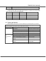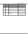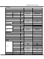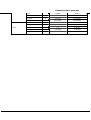
1
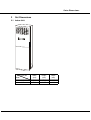
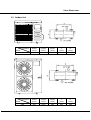
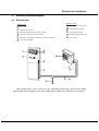
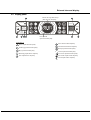
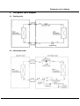
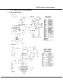
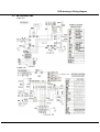
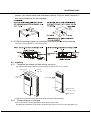
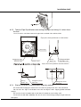
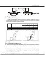
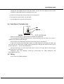
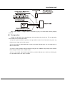
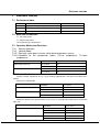
Floor Standing Type Air Conditioner
Model:
MFJ-24ARN1-QB8
MFJ-48ARN1-RB6
Content
CONTENT
1
Safety Precautions .......................................................................................... 1
1.1 Precaution .................................................................................................................... 1
1.2 Installation ................................................................................................................... 1
1.3 Caution ......................................................................................................................... 1
1.4 Operational .................................................................................................................. 1
3
Out Dimensions............................................................................................... 3
3.1 Indoor Unit ................................................................................................................... 3
3.2 Outdoor Unit................................................................................................................. 4
4
External view and display............................................................................... 5
4.1 External view ................................................................................................................ 5
4.2 Display panel ............................................................................................................... 6
5
Refrigerant cycle diagram .............................................................................. 7
5.1 Cooling only.................................................................................................................. 7
5.2 Heat pump mode ......................................................................................................... 7
6
PCB drawing & wiring diagram ...................................................................... 8
6.1 MFJ-24ARN1-QB8 ........................................................................................................ 8
6.2 MFJ-48ARN1-RB6 ........................................................................................................ 9
7
Installation detail ........................................................................................... 10
7.1 Installation place .......................................................................................................10
7.2 Installing.....................................................................................................................11
7.3 Refrigerant pipe connecting .....................................................................................13
7.4 Drain Pipe of The Indoor Unit ...................................................................................15
7.5 Wiring .........................................................................................................................15
7.6 Test operation ............................................................................................................16
8
Electronic function ........................................................................................ 17
8.1 Performance Index .................................................................................................... 17
8.2 Main data Introduction.............................................................................................. 17
8.3 Operation Modes and Functions .............................................................................. 17
8.4 Other Functions .........................................................................................................19
9
Characteristic of temperature sensor ......................................................... 20
10
Trouble shooting ........................................................................................... 21
10.1 Protective Function ....................................................................................................21
10.2 Self-diagnosis ............................................................................................................21
10.3 Troubles and Solutions............................................................................................. 22
Safety Precautions
1
Safety Precautions
1.1 Precaution
To prevent injury to the user or other people and property damage, the following instructions
must be followed.
Incorrect operation due to ignoring instruction will cause harm or damage.
Before service unit, be sure to read this service manual at first.
1.2 Installation
For electrical work, contact the dealer, seller, a qualified electrician, or an Authorized service
center.
Do not disassemble or repair the product by yourself.
Sharp edges could cause injury, be especially careful of the case edges and the fins on the
condenser and evaporator.
Be sure the installation area does not deteriorate with age.
Take care to ensure that power cable could not be pulled out or damaged during operation.
Do not place anything on the power cable.
Do not plug or unplug the power supply plug during operation.
Do not store or use flammable gas or combustible near the product.
When flammable gas leaks, turn off the gas and open a window for ventilation before turn the
product on.
If strange sounds, or small or smoke comes from product. Turn the breaker off or disconnect the
power supply cable as soon as possible.
When the product is soaked (flooded or submerged), contact an Authorized service center.
Be caution that water could not enter the product.
Turn the main power off when cleaning or maintaining the product.
When the product is not be used for a long time, disconnect the power supply plug or turn off the
breaker.
1.3 Caution
Always check for gas (refrigerant) leakage after installation or repair of product.
Install the drain hose to ensure that water is drained away properly.
Keep level even when installing the product.
Do not install the product where the noise or hot air from the outdoor unit could damage the
neighborhoods.
Use two or more people to lift and transport the product.
Do not install the product where it will be exposed to sea wind (salt spray) directly.
1.4 Operational
Do not expose the skin directly to cool air for long periods of time. (Do not sit in the draft).
Do not use the product for special purposes, such as preserving foods, works of art, etc. It is a
consumer air conditioner, not a precision refrigerant system.
Do not block the inlet or outlet of air flow.
Use a soft cloth to clean. Do not use harsh detergents, solvents, etc.
1
Safety Precautions
Do not touch the metal parts of the product when removing the air filter. They are very sharp.
Do not step on pr put anything on the product. (outdoor units)
Always insert the filter securely. Clean the filter every two weeks or more often if necessary.
Do not insert hands or other object through air inlet or outlet while the product is operated.
Do not drink the water drained from the product.
Use a firm stool or ladder when cleaning or maintaining the product.
Replace the all batteries in the remote control with new ones of the same type. Do not mix old
and mew batteries or different types of batteries.
Do not recharge or disassemble the batteries. Do not dispose of batteries in a fire.
If the liquid from the batteries gets onto your skin or clothes, wash it well with clean water. Do not
use the remote of the batteries have leaked.
2
Outer Dimensions
2
Out Dimensions
2.1 Indoor Unit
Dimension
Mode
24K
48K
Width
(mm)
Height
(mm)
Depth
(mm)
500
540
1700
1825
290
410
3
Outer Dimensions
2.2 Outdoor Unit
Dimension
Mode
24K
Dimension
Mode
48K
W idth
(mm)
840
Height
(mm)
695
Depth
(mm)
335
A
(mm)
560
B
(mm)
335
W idth
(mm)
940
Height
(mm)
1245
Depth
(mm)
360
A
(mm)
602
B
(mm)
380
4
External view and display
3
External view and display
3.1 External view
Outd oor unit
7 Drain pipe, vent pip e
Indoor unit
1
Air outlet
2
Operation panel
8
Connection cable
3
Horizo ntal airflow control louver
9
Connection pipe
4
Vertic al airflow control louver
10
Refrigerant pipe po rt
5
Remote controller holder(on some models)
11
Air outlet
6
Air inl et(2 sides)
1
3
4
11
2
5
10
9
6
8
7
Note: All the pictures in this manual are for explanation purpose only. They may be slightly
different from the air conditioner you purchased(depend on model). The actual shape shall prevail.
5
External view and display
3.2 Display panel
Room Te mp/Set Temp
/Set Tim er display
7
AUX ILI ARY
FU N CTION
auto
5
A DJU ST
T1 T2 T3 T4
ON/OF F
LOCK
M ODE
TE ST
R UN N ING
FAN
S PEED
1
2
OFF
3
4
Fan speed
operation d isplay
ON
A DJU ST
5
Indicators
Vert ical airflow display
Auto operation display
Hori zontal airflow disp lay
Cool ing operation display
Slee p operation display
Dry operation display
Turbo operation displa y
On t imer operation display
Heating operation disp lay
Off t imer operation dis play
Lock operation display
Fan operation display
6
6
Refrigerant cycle diagram
4
Refrigerant cycle diagram
4.1 Cooling only
4.2 Heat pump mode
7
PCB drawing & Wiring diagram
5
PCB drawing & wiring diagram
5.1 MFJ-24ARN1-QB8
Indoor unit
Outdoor unit
8
PCB drawing & Wiring diagram
5.2 MFJ-48ARN1-RB6
Indoor unit
Outdoor unit
9
Installation detail
6
Installation detail
6.1 Installation place
6.1.1
Indoor Unit
A place which provides the spaces around the indoor unit as required above in the diagram.
A place where is no obstacle near the inlet and outlet area.
A place which can bear the weight of the indoor unit.
A place which allows the air filter to be removed downward.
A place where the reception range is not exposed to direct sunlight.
In the center of the room where possible.
6.1.1.1 Please stand the unit in hard and flat ground;
Please reserve space for installation and maintenance.
6.1.1.2 Please check the elevation difference between the indoor unit and the
outdoor unit, the length of the refrigerant pipe, and the curved places (bend) of
the pipe are no more than the following numbers:Elevation difference: no more
than 10 M (if the elevation difference between indoor and outdoor unit is more
than 10 meters, it is recommended that the outdoor unit be placed above
the indoor unit.)
Pipe length: no more than 20 M
Bends: no more than 5 places
6.1.2 Outdoor Unit
6.1.2.1 Before installing the outdoor unit, you should:
Select a place where no direct sunlight or other heat-radioactivity may reach. A sunshade is
needed if it is
unavoidable.
Select a place that is easy to connect indoor unit's pipe and electric wires.
Avoid a place where combustible gas may leak or stay.
Keep it in mind that water may drain out of the outdoor unit while in "Heat" mode.
10
Installation detail
6.1.2.2 If the outdoor unit is to be installed on a roof or where no constructions are
around, you should avoid hard wind blows directly to the air outlet, because it
may cause trouble for air-flow shortage.
6.1.2.3 Reserve enough space for installation, maintenance and unit-functioning.
Remove as many obstacles as possible nearby.
6.2 Installing
6.2.1
To prevent the indoor unit from falling, you must:
Pay full attention to the unit because its long outer shape makes it easy to fall;
Safety Lock
×
Screws
3.9 25
×
Screws
3.9 25
Air Outlet
Air Inlet
2
Screw hole
(on the unit)
M8 Screws
Firmly fix the unit to the wall and in the ground to avoid accidental falling.
6.2.2
Dismounting the air-inlet grid
Please take off the air-inlet grid before connecting the pipes/wires.
Pull down the two knobs on the grid, take off the two screws, then the air-inlet grid goes free.
11
Installation detail
6.2.3 Take the Pipe Clip off before connecting the pipes and wiring; fit it when these
finished.
Use accessories 4 and 9 to connect the pipes/wires on both sides and back side.
Pipe/wire-hole positions on both sides
Drain Pipe
Refrigerant Pipe
Reamer Joint
Wiring
Hole 35
φ
Reamer Joint
Refrigerant/drain
Pipe hole 80
φ
Pipe/wire-hole position on the bottom
Wiring
Hole 35
φ
6.2.4
Refrigerant/drain
Pipe hole
Refrigerant/drain
Pipe hole
Ship the a/c to the installation place originally packed;
Be careful while hanging the unit because the center of gravity of the unit is not centralized;
Do not make the angle of inclination more than 45 degrees while shipping;(Avoid horizontal
storage)
Be sure the electric insulation work is well done if installed on metal ceiling / wall.
Fix the unit feet with bolts (M10/M8). Be sure the unit is fixed strongly enough to against blast or
earthquake.
12
Installation detail
Make a concrete basement to the unit by the above references.
6.3 Refrigerant pipe connecting
6.3.1
Pipe length and the elevation
The correct refrigerant quantity filled in the 5-meter-long
pipe of the
outdoor unit is marked on
the Product Data Plate. If you have to use longer pipe for every meter plus pipe, the refrigerant
should be added according to the following calculation.
C apacity
Btu/h
24K
48K
P ipe size
GAS
5/8’’ (φ16)
3/4’’ (φ19)
S tandard
length
Max.
(m)
E levation
5
5
B (m)
10
15
LIQUID
1/4’’ (φ9.53)
1/2’’ (φ12.7)
Max.
A dditional
E levation refrigerant
A (m)
20
30
(g/m)
65
90
6.3.2
Piping connection
6.3.2.1 Connecting Of Refrigerant Pipe
a. Only the correctly installing of indoor and outdoor unit done, can the refrigerant pipe be connected.
b. The cut-off valves are completely close before ex-work. Before connecting the refrigerant pipe, be
careful to check whether the valves are completely close.
c. The connecting procedure of refrigerant pipe: first, unscrew the two valves on the outdoor unit and
the pipe-jointing nut on the indoor unit(please keep them care fully). Please connect the refrigerant
pipe according to the manual, the pipe-jointing nut should be screw tightly and no leakage. Note:
you need two wrenches to make balance.
d. When the connecting of refrigerant pipe is finished, before power on the system, you should
13
Installation detail
vacuum the indoor unit through the maintenance port on the cut-off valves, or open the
high-pressure valve, and exhaust the air through the maintenance port on the low-pressure
valve(closed). It will take about ten seconds. Then screw tightly the maintenance port.
(When
supplement the refrigerant, fill through the maintenance port of the low-pressure valves on the
outdoor unit ).
e. Open all the valves completely before power on the system, or it will be sick for low efficiency.
f. Gas leak check. Make sure no gas from connections with leak detector or soap water.
6.3.2.2 Using bronze pipe selling in market
Completely shut the cut-off valves of the outdoor unit (as ex-work status).
After the refrigerant
pipe has been connected with both the indoor and outdoor unit, let the air exhaust out from the
maintenance gap
on he
low-pressure cut-off
valves of the outdoor unit.
Screw the nuts tightly
on the maintenance gap after the air has been drained.
6.3.2.3 To make the refrigerant pipe unblocked completely
you should keep the cut-off valves of the outdoor unit completely open after you have finished
the above steps (step1) or step 2))
Note: Before screwing the reamer nut, smear the pipe and the connecting surface with
refrigerant oil; Check and make sure there is no leakage by soap-water or leakage-checker after
connecting;
Be sure the connecting joint on the indoor side is insulated.
Use two wrenches to connecting the pipes.
Tubing size
Torque
9.52
3270~3990N.cm(333~407kgf.cm)
12.7
4950~6030N.cm(504~616kgf.cm)
16
6180~7540N.cm(630~770kgf.cm)
19
9720~11860N.cm(990~12106kgf.cm)
6.3.3
Air Purging
When Using the Vacuum Pump
(For method of using a
manifold valve, refer to its operation manual.)
a. Completely tighten the flare nuts, A, B, C, D, connect the manifold valve charge hose to a
charge port of the low-pressure valve on the gas pipe side.
b. Connect the charge hose connection to the vacuum pump.
c. Fully open the handle Lo of the manifold valve.
d. Operate the vacuum pump to evacuate. After starting evacuation, slightly loose the flare nut of
the Lo valve on the gas pipe side and check that the air is entering.(Operation noise of
vacuum
pump changes
and
a
the
compound meter indicates 0 instead of minus)
e. After the evacuation is complete, fully close the handle Lo of the manifold valve and stop the
operation of the vacuum pump. Make evacuation for 15 minutes or more and check that the
compound meter indicates
-76cmHg (-10x106Pa).
14
Installation detail
f. Turn the stem of the packed valve B about 45 counterclockwise for 6~7 seconds after the gas
coming out, then tighten the flare nut again. Make sure the pressure display in the pressure
indicator is a little higher than the atmosphere pressure.
g. Remove the charge hose from the low pressure charge hose.
h. Fully open the packed valve stems B and A.
i. Securely tighten the cap of the packed valve.
6.4 Drain Pipe of The Indoor Unit
Make sure the drainpipe is connected to the outdoor side downward;
The hard polyvinyl chloride(PVC)plastic pipe (external diameter 26 mm) sold is the market is
suitable for the attached soft drain pipe;
Please connect the Soft Drain Pipe with the Drain Pipe, then fix it with band;
If you have to connect the Drain Pipe indoors, to avoid condensing caused by air intake, you
must cover the pipe with heat-insulation material (polyethylene with Specific Gravity of 0.03, at least
9 mm in thickness), and use Glue Band to fix it.
After the Drain Pipe has been connected, please check if the water drains out of the pipe
efficiently and has no leakage.
Refrigerant pipe and Drainpipe should be heat-insulated to avoid condensing and
water-dropping later on.
6.5 Wiring
Please refer to the Wiring Diagram.
15
Installation detail
≥
2
(Wiring size: 2.5mm )
≥
2
(Wiring size: 2.5mm )
Note: Some models is equipped with a cord having a plug, So a wall outlet shall be properly
installed.
6.6 Test operation
Perform test operation after completing gas leak and electrical safety check. The test operation
time should last more than 30 minutes.
1). Open the panel and lift the panel up to angle which remains fixed. Do not lift the panel any
further when it stops with a "click"sound.
2). Press the manual switch button twice until the operation indicator lights, the unit will operate on
Manual Cool mode.
3). Check if all the functions work well while testing the air conditioner. Especially check whether
the drainage of indoor unit is smooth or not.
4). Press the manual switch button again till the operation indicator turns dark after finishing the
test operation and the unit stops operation.
16
Electronic function
7
Electronic function
7.1 Performance Index
No.
Item
Index
1
Applicable Voltage Range
185-253V, 342-418V
2
A/C Frequency
50Hz
3
Working environment temperature
-7°C- +45°C
7.2 Main data Introduction
Ts : Set temperature,
T1 : Room temperature
T2: Evaporator pipe temperature
7.3 Operation Modes and Functions
7.3.1 Manual Operation
7.3.2 Heating Mode
7.3.2.1 Four-way valve opens at once, while defrosting process closes.
7.3.2.2 Condition for the compressor action: (Ts=set temperature, T1=room
temperature)
Room temperature up
Room temperature down
Condition
Compressor and outdoor fan
T1-Ts=0°C
Off
T1-Ts>-1°C
On
T1-Ts<-1°C
On
T1-Ts=0°C
Off
7.3.2.3 Indoor Fan Action
Anytime remote switchover for fan speed among high/low/auto, anti-cold air function takes
priority.
Auto fan in heating mode
Room temperature up
Room temperature down
Condition
Fan speed
T1-Ts>-1°C
Low
T1-Ts<-1°C
Hi.
T1-Ts<-2°C
Hi.
-2°C <T1-Ts <-1°C
Low
Anti-cold air:
Switchover between fan speed and fine tune can be set according to temperature of evaporator
pipe (T2).
Room temperature up
Room temperature down
Condition
Fan speed
T2<25°C
Off
25°C <T2<32°C
Low
T2>32°C
Set fan speed
T2>22°C
Set fan speed
20°C <T2<22°C
Low
17
Electronic function
T2<20°C
Off
7.3.3 Defrost (only available to heating mode)
7.3.3.1 Defrosting Conditions
Starting Of Defrosting Condition (meet one of the following is ok):
(1)Accumulated compressor operating time when temperature of outdoor heat exchanger coil
T3 is below -2°C reaches up to over 46 minutes.(When T3 is over 20°C, calculate time again.)
(2) Under evaporator high temperature protection, the accumulated time when outdoor fan
motor is off and compressor is on reaches up to over 90 minutes .(When T3 is over 20°C, calculate
time again.)
High temperature defrosting condition:
Under high temperature protection of evaporator, the time when outdoor fan is shut down but
compressor is not has been accumulated for up to 90 minutes.
7.3.3.2 Defrosting Action
Four-way valve, indoor fan, outdoor fan are shut down. Compressor keeps on.
7.3.3.3 Ending Of Defrosting Condition (meet one of the following is ok):
(1)Time of defrosting lasts 10 minutes.
(2)Temperature of outdoor coil T3 is up to 20°C.
7.3.4 Cooling Mode
7.3.4.1 Four-way valve is closed.
If four-way valve is open before the machine enters cooling mode, then four-way valve will be
closed at the first time, the compressor starts under the cooling mode.
7.3.4.2 Conditions for the compressor and outdoor fan action (Ts = set temperature)
Room temperature up
Room temperature down
Condition
Compressor and outdoor fan
T1-Ts=0°C
Off
T1-Ts>1°C
On
T1-Ts>0°C
On
T1-Ts=0°C
Off
7.3.4.3 Action of Indoor Fan
HIGH/LOW/AUTO fan can be switched over by your comfort.
Auto fan under cooling mode.
Room temperature up
Room temperature down
Condition
Fan speed
T1-Ts>2°C
Hi.
1°C < T1-Ts <2°C
Low
T1-Ts>1°C
Hi.
T1-Ts <1°C
Low
7.3.5 Dehumidifying Mode
7.3.5.1 Indoor fan speed is low.
7.3.5.2 If certain protective condition is met, operation will be carried out.
18
Electronic function
7.3.6 Auto Mode
7.3.6.1 Under auto mode, the indoor fan is set to be auto.
7.3.6.2 When entering auto mode, the heating, fan only or cooling operation will be
automatically chosen according to the room temperature T1 and the set
temperature Ts.
Condition
Mode
T1-Ts>1°C
Cooling
-1°C< T1-Ts<1°C
Fan
T1-Ts<-1°C
Heating(fan for cooling only type)
7.3.6.3 After one mode is chosen, if the condition lasts for 15 minutes, meanwhile the
compressor doesn't start up within consecutive 15 minutes, the operation mode
will be re-chosen according to the T1and Ts.
7.3.6.4 If certain condition is met, then the corresponding protective function will be
executed.
7.3.7 Fan Only Mode
7.3.7.1 Under this mode, four-way valve, compressor and outdoor fan are shut down.
7.3.7.2 High/Low/Auto fan can be switched over through manual control. Auto fan will
be controlled in line with cooling auto fan with temperature set to be 24C.
7.4 Other Functions
7.4.1
LCD display
Mode, Set temp.,fan speed, time, timer, protection etc.
7.4.2
Timer
The machine should be provided with max. Interval of 24h and min. resolution ratio of 15
minutes.
19
Characteristic of temperature sensor
8
Characteristic of temperature sensor
℃
Temp.
-10
-9
-8
-7
-6
-5
-4
-3
-2
-1
0
1
2
3
4
5
6
7
8
9
10
11
12
13
14
15
16
℃
Resistance KΩ Temp.
62.2756
17
58.7079
18
56.3694
19
52.2438
20
49.3161
21
46.5725
22
44
23
41.5878
24
39.8239
25
37.1988
26
35.2024
27
33.3269
28
31.5635
29
29.9058
30
28.3459
31
26.8778
32
25.4954
33
24.1932
34
22.5662
35
21.8094
36
20.7184
37
19.6891
38
18.7177
39
17.8005
40
16.9341
41
16.1156
42
15.3418
43
℃
Resistance KΩ Temp.
14.6181
44
13.918
45
13.2631
46
12.6431
47
12.0561
48
11.5
49
10.9731
50
10.4736
51
10
52
9.5507
53
9.1245
54
8.7198
55
8.3357
56
7.9708
57
7.6241
58
7.2946
59
6.9814
60
6.6835
61
6.4002
62
6.1306
63
5.8736
64
5.6296
65
5.3969
66
5.1752
67
4.9639
68
4.7625
69
4.5705
70
20
Resistance KΩ
4.3874
4.2126
4.0459
3.8867
3.7348
3.5896
3.451
3.3185
3.1918
3.0707
2.959
2.8442
2.7382
2.6368
2.5397
2.4468
2.3577
2.2725
2.1907
2.1124
2.0373
1.9653
1.8963
1.83
1.7665
1.7055
1.6469
Exploded view & spare-part
9
Trouble shooting
9.1 Protective Function
9.1.1
3-minute delay for the compressor start-up
At the beginning of energizing or after the stop of the compressor, 3-minute delay will be needed
to start the compressor.
When switching over between cooling/heating mode, the compressor stops automatically.
9.1.2 Evaporator protection against high temperature
9.1.2.1 Only available under heating mode.
9.1.2.2 The operation principle is as follows: (T2 = evaporator temperature)
Condition
Outdoor fan
Compressor
T2>56°C
Off
On
T2>62°C
Off
Off
T2<62°C
On
Off
T2<50°C
On
On
Note: During protection, the indoor fan continues operating at a set speed, while the anti-cold air
function of heating and the compressor will be 3 minute delayed to shut down for protection.
9.1.3 Evaporator Protection against low temperature
9.1.3.1 Only available under cooling and dehumidifying status.
9.1.3.2 Protection principle:
Condition
Outdoor fan
Compressor
T2<2°C
Off
Off
On
On
(last 3 minute)
T2>8°C
9.1.3.3 The restart of the compressor shall execute the delay protection.
9.1.4 Condenser high temperature protection
9.1.4.1 Only available to cooling and dehumidifying mode.
9.1.4.2 Action condition
Condition
Outdoor fan
Compressor
Condenser temp.>62°C
Off
Off
Condenser temp.<48°C
On
On
9.1.4.3 Delay protection should be performed when the compressor restarts.
9.1.5 Outdoor protection
When outdoor protection signal is high level, outdoor unit will perform protection: the whole
machine will be shut down while the indoor unit will indicate the corresponding protection signal.
The A/C will recover if outdoor errors are eliminated after the outdoor protection occurs.
9.2 Self-diagnosis
Codes
Contents
P4
Protection of temperature of indoor evaporator
P5
Protection of temperature of outdoor condenser
P9
Protection of defrosting or anti-cold wind
E1
Open-circuit and short-circuit of temperature sensors T1
E2
Temp. sensor T2 on indoor evaporator is open circuit or short circuit
21
Exploded view & spare-part
E3
The condenser temperature sensor T3 is open or short
E6
Protection of outdoor unit
9.2.1
LEDs for the indication of outdoor trouble
In normal operation, LEDs emit no light and they will flash at a frequency of 5 Hz when trouble
occurs. Their codes are listed in the following table:
LED1
LED2
LED3
Contents
Off
Off
On
Ok
On
Off
On
Phase sequence error
Off
On
On
Overload of current
On
On
On
Lack of phase
9.3 Troubles and Solutions
Before calling for service, please review the following list of common problems and solutions.
If any of the following conditions occur, check your unit and resolve corresponding problems referring
to given remediation. If the trouble can't be settled contact our dealer.
Trouble
Cause
Solutions
Unit does not start
Power failure.
Wait for the comeback of power
Power switch is open.
Switch on the power
Fuse of power switch may have blown.
Replace the fuse
Batteries remote controller are exhausted.
Replace the batteries
The time is not start-up time you have set.
Wait or cancel the time set.
Air flowing normally
Temperature is not set correctly.
Set the temperature properly.
with
low
Door or window is open.
Close door and window.
cooling(heating)
Air filter is blocked with dust or dirtiness.
Clean the air filter.
effect
Inlet/outlet of indoor/outdoor units are
Clear all blockages.
blocked.
Inlet/outlet of indoor/outdoor units are
Clear the blockage, then restart
blocked.
your operation.
Be in 3 minutes protection of compressor
Wait
22
Exploded view & spare-part
Number
Display code
Problem
What to do
1
E1 E2 E3 E4
Temperature Sensor is off or short-circuit.
Contact service people
2
E6
Outdoor unit protection
Contact service people
3
E8
Electrostatic dust collection
Contact service people
The temperature of the evaporator of indoor
Turn off the unit, clean the air
unit is too low or high (For the protection
filter, then restart the unit. If this
feature,
operation does not work, please
4
P4
the
compressor
turns
off
automatically)
5
contact service people.
The temperature of condenser of the
P5
outdoor unit is too high (For the protection
feature,
the
compressor
turns
off
automatically)
6
P9
Defrosting
protection
controlling is off
or
warm-air
Turn off the unit, check if there is
any obstacle
in
the
air-inlet,
otherwise call the service people.
The unit will auto restart after
finishing the defrosting or the
temperature
of
the
Heat
Exchanger of indoor unit raise.
23
Exploded view & spare-part
Specification
Model
MFJ-24ARN1-QB8
MFJ-48ARN1-RB6
Factory Code
2T004330T031
2T004370T020
Ph-V-Hz
1φ,220-240V,50HZ
3φ,380-420V,50HZ
Electrical Data
Power supply
Capacity
Cooling/Heating
Btu/h
24000/27000+7200
46000/49000+12000
Power consumption
Cooling/Heating
W
2500/2450+2100
5200/5100+3500
Rated current
Cooling/Heating
A
12/11.5+9.6
8.6/8.5+5.6
EER
Cooling/Heating
Btu/w.h
9.5/10.9
8.9/10.2
Refrigerant type
g
R410A/2000
R410A/4500
Design pressure
MPa
4.2
4.2
Air flow
m3/h
1100
1750
Indoor
dB(A)
48
50
Outdoor
dB(A)
60
62
mm
500x1700x290
540x1825x410
mm
615x1805x415
655x1935x555
Net/Gross weight
Kg
41.5/58.5
58/75
Dimension
mm
840x695x335
940x1245x360
mm
965x755x395
1018x1380x435
Kg
60/63
104/115
mm
Ф9.53/Ф16
Ф12.7/Ф19
Max. refrigerant pipe length
m
20
30
Max. difference in level
m
10
15
Ambient temp
℃
-7-45
-7-45
Application area
m2
40-56
80-112
PA290X3CS-4MU1
C-SBN373H8D
Type
Rotary
Scroll
Brand
GMCC
Sanyo
Btu/h
24490
48109
Input
W
2430
4750
Rated current(RLA)
A
11.4
8.22
Locked rotor Amp(LRA)
A
61
66
UP14SE5145
internal
System data
Noise level
Dimension&Weight
Dimension
Indoor
Outdoor
Packing
Packing
(W*H*D)
(W*H*D)
(W*H*D)
(W*H*D)
Net/Gross weight
Refrigerant piping
Liquid side/ Gas side
Applicable ambient
Compressor
Model
Capacity
Compressor
Thermal protector
Capacitor
uF
50
No
Refrigerant oil
ml
950
1700
YDK75-8
YDK120-8T
Fan Motor
Indoor
Model
24
Exploded view & spare-part
Brand
Welling
Input
W
164
300
Capacitor
uF
5UF/450V
6.5UF/450V
r/min
575/540/440
600/550/480
Model
YDK100-6D
YDK65-6F/YDK65-6
Brand
Welling
Welling
Speed(high/low)
Outdoor
Welling
Input
W
170
156/148
Capacitor
uF
5UF/450V
3.5UF/450V
r/min
900
800
Speed
25