1
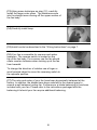
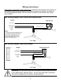
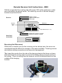
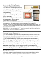
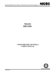
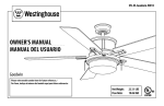
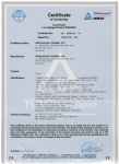
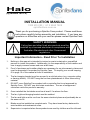
Halo
(by Modern Fan Co.)
INSTALLATION MANUAL
1300 935 285 / 61 2 9960 7828
spinifexfans.com.au
Thank you for purchasing a Spinifex Fans product. Please read these
instructions carefully before assembly and installation. If you have any
questions or difficulties with your new fan please contact Spinifex Fans.
SAFETY WARNING
Ceiling fans and other fixed wire products must be
installed by a licensed electrician in compliance with
Australian Standards and other Government
regulations.
Important Information - Read Prior To Installation
1.
Nothing in this manual is intended to instruct or assist untrained or unqualified
persons to install this product. Additionally it is the responsibility of the installer and
user to apply common sense and care at all times.
2.
Proof of purchase and installer details are necessary for on-site warranty claims and
must be presented if requested by Spinifex Fans. To simplify your record keeping,
fill in page 10 of this manual at time of installation.
3.
The fan hanging bracket must be secured to a solid structure (e.g. concrete ceiling
or framing timber). DO NOT hang the fan from plasterboard or other false ceiling
material.
4.
DO NOT use a Spinifex Fans product with a controller that is not approved by
Spinifex Fans. DO NOT use solid state controllers. The use of unapproved
controllers voids the product‟s warranty.
5.
Once installed the fan blades must be at least 2.1m above the floor.
6.
The fan, light and hanging bracket must be earthed.
7.
The fan and light must be run from the same electrical phase and preferably be on
the same circuit.
8.
Blades must be installed as complete sets. They have been factory balanced to
avoid wobble and mechanical noise.
9.
Supervision is required when these products are used by children and the infirmed.
Safety
Read this instruction manual thoroughly before installing or using this appliance
and save the instruction manual for future reference and if necessary pass it on
to a third party.
WARNING: When using electrical appliances, basic safety precautions should
always be followed to reduce the risk of fire, electrical shock and personal injury.
Identification of safety and warning symbols
Read the instructions
Lamp
Caution
Protective earth
General safety precautions
8. The electrical wiring must be in accordance
with the local regulations.
9. The fan must be properly grounded to avoid
the risk of electrical shocks.
10. The minimum carrying capacity of the outlet
box from which the fan is hung must be
100kg.
11. If a lamp is installed with the fan then the
lamp‟s wattage should not exceed that
shown on the lampholder.
12. The mains supply to the appliance must be
via a pole disconnection switch (live and
neutral wires) and the switch must have a
contact separation of at least 3mm.
13. To reduce the risk of fire or injury, do not
use this ceiling fan in conjunction with any
variable (Rheostat) wall controller or
dimmer.
14. This appliance is for indoor use only.
15. This appliance is considered to be suitable
for use in countries having a warm damp
equable climate. It may also be used in
other countries. If the appliance is installed
in a warm damp equable climate the
appliance is to be supplied through a
residual current device (RCD) having a
rated residual operating current not
exceeding 30 mA.
1. Check if the electrical specifications of this
appliance are compatible with your
installation.
2. Unauthorised use and technical
modifications to the appliance can lead to
danger to life and health.
3. This appliance is not intended for use by
persons (including children) with reduced
physical, sensory or mental capabilities, or
lack of experience and knowledge, unless
they have been given supervision or
instruction concerning use of the appliance
by a person responsible for their safety.
4. Children should be supervised to ensure
that they do not play with the appliance.
5. Means for disconnection must be
incorporated in the fixed wiring in
accordance with the wiring rules.
6. Be careful when working near the rotating
blades.
7. Never attach the fan to a power point, but to
the ceiling itself.
8. Switch OFF the power before connecting or
repairing the fan.
2
Assembly & Installation
(1) Remove and identify contents of carton.
Canopy
Fan body
Blades
Outer glass
Inner glass
Hardware
package
Controls:
- Wall dial
- Optional
remote
Balancing
kit
Down rods
Half ball
Hanging bracket
Note: Some components
may be packaged or
appear slightly different
from those shown here.
Disposal
Do not dispose of electrical appliances as unsorted municipal waste. Use separate
collection facilities and if necessary contact your local government for information
regarding the collection systems available.
If electrical appliances are disposed of in landfills or dumps, hazardous substances
can leak into the groundwater and get into the food chain, damaging your health
and well-being.
3
(2) Using the existing screws from your junction box,
or the machine screws from the hardware package,
secure the hanging bracket to the ceiling junction
box.
CAUTION: The fan must be mounted onto a
structural member capable of carrying at least
100kg.
(3) Remove top cover by loosening the three screws
holding it in place. Set cover aside to replace after
blade installation.
Top cover screws
Top cover
(4) Insert one blade into rotor slot. Using blade
screws from hardware package, secure blade to
rotor. Start all three screws before completely
tightening. Repeat for all blades.
(5) Remove stopper pin and half ball from small down
rod by loosening set screw on half ball. Set all parts
aside for step (9).
Stopper pin
Set screw
(6) Replace top cover from step (3), ensuring
“reverse” switch opening is properly located. Then
remove the stopper screw and loosen the set screw
on the fan collar. Set the stopper screw aside for
step (7).
Stopper screw
Set screw
(7) Run fan wires through selected down rod. Reinstall stopper screw from step (6) and firmly tighten set
screw on fan collar against down rod.
Note: If ceiling height allows, using a longer down rod
will increase airflow and efficiency.
4
(8) Slide fan canopy over down rod and carefully rest
on top of fan body.
Canopy
(9) Reinstall half ball on end of down rod. Be sure that
stopper pin is inserted through down rod and seated in
half ball. Tighten set screw against down rod.
Stopper pin
Set screw
(10) Lift fan to ceiling and set half ball in the hanging
bracket so that the ridge on the edge of the hanging
bracket is seated in the slotted channel in the half ball.
With fan safely suspended by bracket, make wire
connections as described in “Wiring Instructions” on
page 7. If using a remote control the receiver unit
should be placed inside the arms of the hanging
bracket and connected at this time.
(11) Loosen set screws on the sides of the hanging
bracket. Lift canopy to ceiling. With holes in side of
canopy aligned with set screw holes on hanging
bracket, reinstall set screws to hold canopy in place.
Set screw
(12) Carefully install the smaller inner glass using the
fasteners included in the hardware package. The
fasteners screw into the „L‟ shaped arms coming off
the lower section of the fan body.
Tip 1: A second pair of hands can be very helpful.
Tip 2: Only partly screw in each fastener until all
three are in place, then tighten just firmly enough to
keep glass from moving.
Warning: DO NO over tighten fasteners
5
Channel &
ridge
(13) Using same technique as step (12), carefully
install the larger outer glass. The fasteners screw
into the straight arms coming off the upper section of
the fan body.
(14) Carefully install lamp.
(15) Install control as described in the “Wiring Instructions” on page 7.
(16) Your fan is reversible for summer and winter
operation. The reverse switch is located on the
top of the fan body. For summer use the fan should
rotate counter clockwise when looking up at the fan
from beneath.
To change the direction of rotation use a finger or
small pointed object to move the reversing switch to
the opposite position.
(17) The rotor and motor of your fan have been dynamically balanced at the
factory. In addition, the blades have been matched to the nearest gram to
ensure a well balanced ceiling fan. Furthermore, a blade balancing kit has been
included with your fan. Please refer to the instructions packaged with the
balancing kit should your fan require additional balancing.
6
Wiring Instructions
With power turned OFF at the switch box, make wire connections from the fan to
the power at the ceiling, and from the control to power at wall box as shown in
the wiring diagrams below. Secure control to wall box and attach cover plate
over control.
#001 Wiring Diagram: Wall Control with optional light
Supply
Wall Control
Red Active
Black Neutral
Green Earth
Brown Fan Active
Blue Light Active (Optional)
Notes:
1. Colours are representative only.
2. Terminal blocks are included
with some hanging brackets.
3. Cap seal light wire if a light
fitting is not being used.
Fan / light
#003 Wiring Diagram: Hand Held Remote
Remote Receiver
Supply
Red Active
Black Neutral
Brown Fan Active
Green Earth
Black Neutral
Blue Light Active (Optional)
Fan / light
WARNING: Do not use a Spinifex Fans product with a controller that
is not approved by Spinifex Fans. Do not use solid state controllers.
The use of unapproved controllers voids warranty.
7
Remote Receiver Unit Instructions - #003
With fan suspended from ceiling and with power OFF at the switch box, make
wire connections as shown below. The receiving unit sits in the ball hanging
bracket as pictured below.
White neutral
Black or red active
Blue light
Receiver
Antenna
Dimmer
Switch
(#1)
1
2 3 4
Dip Switches (# 2, 3, 4)
White A/C power in neutral
Black A/C power in active
Hand held
transmitter
AAA 1.5v
1
2 3 4
AAA 1.5v
Receiving Unit Placement
While there is ample room for the receiving unit as shown here, the wires can
sometimes become difficult to manage in the space available. Trimming excess
wire before making connections can ease wire management.
Tip: Insert the remote from the side of the hanging bracket that does not have
terminal blocks for joining wires to ensure the ceiling canopy mounts evenly to
the ceiling. Then run wiring from the receiver unit to the terminal blocks on the
outside of the hanging
bracket.
8
Instructions for Setting Remote
Frequency (Dip switches 2, 3 & 4)
Your hand-held remote Control (#003) is
a two component system. The handset is
preset to the same frequency as the
receiving unit. You may want to change
these settings if:
(a) Other radio frequency signals or
appliances are interfering with operation
of your ceiling fan.
(b) You are installing more than one fan
in close proximity, and you want to
control these fans separately.
Ensure power to your fan and switch is OFF. Locate dip switches 2, 3 & 4 as
pictured above, and carefully select a new combination of ON and OFF
switches. Be sure the combinations match on the handset and the receiving unit.
Turn power back ON and test that the new frequency corresponds and that your
fan is functioning properly.
WARNING: Do not use dip switch “1”, which controls the light dimming function
of the remote and does not alter its frequency.
Dimming Function (Dip switch 1)
Your remote has been preconfigured to include dimming for your optional light.
If you are using globes that are non-dimmable or you do not wish to use the
dimming function it can be turned off.
To turn off the light dimming function ensure power to your fan and switch is
OFF. Locate dip switch #1 on both the handset and the remote receiver and
move it to the OFF position (typically down closer to the “1”). Turn power back
ON and test that dimming function is no longer operational.
To turn the dimming function ON move the dimming switch to the ON position.
WARNING: When turning OFF the dimming function ensure the light is at
maximum brightness before turning it OFF, otherwise the current to the light may
be reduced, resulting in a dimmer than desired light.
Operation Instructions
With power supply ON, use the handset to send commands to the fan and/or
light. To dim light, hold down light button until desired level is reached.
9
Ceiling Fan Warranty Details
To simplify the process in the unlikely event of a warranty claim, please record
the following information at the time of installation and file with your purchase
receipt.
Customer Details
Name:
Address:
Phone Number:
Fan Details
Purchase date:
Retailer:
Model:
Colour:
Blade span:
Electrician Details
Name:
License No.:
Phone Number:
V. 2810
10
Maintenance Instructions
1.
2.
3.
4.
5.
6.
7.
8.
Because of the fan‟s natural movement some connections may become loose.
Check the support connections, brackets and blade attachments periodically.
Make sure they are secure. If it is necessary to remove the fan from the ceiling or
access parts of the fan that carry lethal voltage contact a licensed electrician, at
your own cost.
Clean your fan periodically to help maintain its new appearance over the years.
Use only a soft brush or lint free cloth to avoid scratching the finish. Plated
finishes are sealed with lacquer to minimise discolouration or tarnishing. DO NOT
use water when cleaning, this could damage the motor, wooden blades or possibly
cause an electric shock.
There is no need to oil your fan. The motor has permanently lubricated bearings.
If your fan is provided with a light diffuser, remove and clean the diffuser with
lukewarm soapy water and a soft cloth or sponge. DO NOT immerse light diffuser
in hot water. DO NOT put light diffuser into an automatic dishwasher.
When replacing a halogen globe ensure you do not touch it with your hands as the
oils on your skin can reduce its life.
From time to time the battery in the remote control will require replacement.
This electrical product is manufactured in accordance with the relevant safety
standards. Repairs should only be carried out by qualified persons using original
spare parts.
If the ceiling fan has not been used for a long time, turn it ON and let it run for
several minutes in order to keep it in good working order.
Note: After cleaning your fan make sure the down rod is vertical otherwise the fan
may wobble.
Seasonal Use
Winter - Clockwise rotation to bring
warm air down the walls from the ceiling
without producing a strong draft beneath
the fan.
11
Summer - Anti-clockwise rotation to provide a cooling breeze beneath the fan
and circulate air around the room.
Trouble Shooting Tips
General information:
All electric motors, including fan motors, make some noise and may feel hot to
the touch. This is not a fault of the ceiling fan.
In some areas signals are sent through the power lines by the electricity supplier
for the control of off peak hot water, street lights and other electrical systems.
These signals may cause an intermittent humming in the ceiling fan. Filters can
be purchase to address this at the customer‟s cost. This is not a fault of the
ceiling fan.
Often noises such as ticking or humming can be caused by loose parts or
structural factors in the ceiling. Please review the trouble shooting tips listed
below to fix the problem.
CAUTION: A number of the items below require access to areas of the
fan which carry lethal voltage. These are marked with the caution
symbol and can only be performed by a licensed electrician in
compliance with Australian Standards and other Government
regulations. Apply common sense and care at all times.
Blades do not turn
Check mains power has been turned ON.
Check circuit breakers and fuses.
Check that the reverse switch is firmly in one position.
Check wire connections at ceiling and wall control.
Fan makes humming noise
Be sure that all non-electrical fittings (light kit, bottom dome, canopy, etc)
are firmly secured. Loose parts may cause vibration noise or humming.
Be sure you are using a control approved by Spinifex Fans. Rheostats,
continuous dimmers and low-voltage controls will cause motor noise.
Fan wobbles
Check that the down rod is vertical.
Make sure all mounting hardware at ceiling is tight.
Be sure ridge in hanging bracket is seated in the half-ball slot.
Check that stopper screws and set screws are firmly tightened where
down rod is attached to the fan body.
Ensure screws attaching blades to rotor are tight.
Have blade sets been mixed? Blade sets are pre-balanced and must be
used as part of the provided set.
Use blade balancing kit as instructed in kit.
12
Light does not work or flickers
Several models have a manual ON / OFF switch for the light located on the
fan body. Be sure it is in the ON position.
Be sure the globe is screwed in completely so that base touches contacts.
Check globe has not blown.
Confirm the right globe is being used.
Check wire connections at ceiling and wall control.
Fan makes repetitive ticking noise
Check for obstructions in rotor path.
Check light kit globes are secure.
Make sure all other hardware is tight.
Make sure mounting hardware at ceiling is secure.
Fan (or light) not responding to remote
Check the battery has charge.
Confirm dip switch settings are the same on sending and receiving units.
Check that all wire connections are made as instructed and are secure.
Unable to operate fan and light independently
Be sure you are using a fan speed control approved by Spinifex Fans.
Check wire connections at ceiling and wall are made as instructed.
Missing or short wires
Check if wires are stuck in the fan housing.
Fan turns but does not move much air
Check that the fan is not in the „reverse‟ position for winter operation.
Confirm that there is sufficient distance between the ceiling and blades for
air convection - typically about 30cm between ceiling and fan blades.
For high ceilings, consider using an extension down rod to bring the fan
closer to the floor.
Fan speed is not corresponding to the wall controller
Check the wall controller has been wired correctly.
Further Trouble Shooting Assistance
If the problem continues after reviewing the trouble shooting tips, please contact
Spinifex Fans before the electrician leaves the site.
61 2 9960 7828
13
Warranty
Ceiling fans
Please select your fan carefully and discuss your needs with a sales professional who knows your
local area. Fans that do not perform as expected and which are not faulty cannot be replaced or
exchanged under warranty. Proper performance relies on the right fan being correctly installed in
the optimum location.
The ceiling fan itself (excluding accessories, such as remote controls, light kits and blades) has a 2
year in-home warranty. During this period Spinifex Fans will, at its discretion, repair or replace the
defective product. Following the in-home warranty Spinifex Fans offers a further 3 year parts only
warranty on the fan motor. Fans installed in commercial locations are covered by a 90 day parts
only warranty. Blades are warranted on a 12 months parts only basis.
Remote controls
All Spinifex Fans‟ remote controls have a 12 month in-home warranty for the remote control receiver
and a 12 month parts only warranty for the hand piece. Please note that the remote control is not
part of the fan, instead being a separately connected accessory device. Resetting of remote DIP
switches in the remote hand piece is not covered by the warranty. Information on how to correctly
set the DIP switches is located in this manual. Batteries, if supplied, are done so as a complimentary
(free) item only and are not covered by warranty.
Light kits
All Spinifex Fans light kits have a 12 month warranty. Globes, if supplied, are done so as a
complimentary (free) item only and are not covered by warranty.
What is the in-home warranty?
The warranty does not cover installation faults, house wiring faults, loose blades or fittings or
damage of any kind. If you are located beyond 25km from the depot of our service agents, Spinifex
Fans will reimburse customers a standard fee of $85 (inc. GST) for using their own electrician.
Conditions apply and any service request must be arranged with Spinifex Fans before calling your
own electrician.
When installed as recommended by Spinifex Fans (via an isolation switch) a fan or remote control
can be switched OFF at the wall in case of a fault. If the product cannot be switched OFF because
an isolation switch is not fitted, costs involved in disconnecting the product while awaiting warranty
service are borne solely by the customer.
What is the parts only warranty?
Spinifex Fans will supply parts only, shipped to the customer or their nominated agent. Conditions
apply. Please note labour associated with installation of these parts, or associated electrical costs of
removing and reinstalling the product to effect repair is borne by the customer.
Balance of warranty
Any replaced or repaired product is covered only by the balance of the warranty remaining on the
original article.
14
Transfer of warranty
If the dwelling where the fan or remote control is installed changes hands, the balance of the
warranty passes to the new owner, with the same eligibility requirements passing to the new owner.
Eligibility
Warranty periods begin from the day of purchase. Product, installing electrician, purchase details
and proof of purchase must be presented to claim the warranty.
Fans and fixed wiring products must only be installed by persons who are appropriately licensed by
the applicable state regulatory body. The warranty will not be provided if products have been
installed by unlicensed persons.
Damages caused by incorrect installation, force-majeure, electrical surges, lightning, power grid
fluctuations, water, salt spray, weather, or by connection to alternative power supply sources (such
as solar inverters etc), are not eligible for warranty repair.
This warranty offer excludes corrosion damage such as surface rust. Regular maintenance (e.g.
cleaning) will generally prevent this occurring.
This product warranty excludes liability for consequential loss or claims for damage to furniture,
carpet, walls, ceilings, foundations or any other event either directly or indirectly resulting from a
faulty ceiling fan or accessory product. This warranty will not cover any repairs to a Spinifex Fan
product where the product was incorrectly used, physically abused, accidentally damaged or not
serviced in accordance with our maintenance instructions.
Signals sent through the power grid by the electricity supplier for the control of off peak hot water,
street lights and other devices may cause an intermittent humming noise in your electrical appliances
such as your ceiling fans. These noises do not occur as a result of a faulty fan.
When products are installed in a location requiring special access equipment (such as scaffolding,
scissor lifts, etc) the cost of providing, installing and operating special access equipment must be
borne by the site owner. The need for, or use of, such equipment must be stated when booking a
service call. Charges will be levied for Spinifex Fans to arrange special access equipment.
Blades must be replaced only as complete sets. Blades are supplied only as a pre-balanced set and
the replacement of individual blades may void the warranty by causing mechanical damage to the
motor, excessive noise or premature wear. Mixing up of blades sets when fans are installed or
maintained may void your warranty. Re-sorting mixed blades is not covered under the warranty.
If goods are found to be free of defects or the product is not functioning properly as a result of faulty
installation or maintenance then Spinifex Fans reserves the right to charge the customer a service
fee.
DO NOT uninstall fan and DO NOT return product to the retailer unless advised to do so by a
Spinifex Fans‟ staff member. Call Spinifex Fans on (02) 9960 7828.
The Spinifex Fans warranty is only available for Spinifex Fans products that are purchased and
installed within Australia.
15
Spinifex Fans Pty Ltd
Australia: 1300 935 285
International: 61 2 9960 7828
Fax: 61 2 9475 4557
Email: [email protected]
www.spinifexfans.com.au
PO Box 202
Spit Junction, NSW, 2088
ABN: 99 139 738 613
16