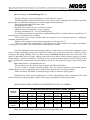
1
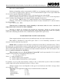
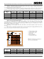
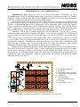
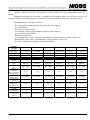
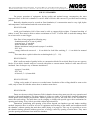
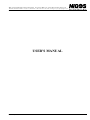
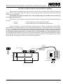
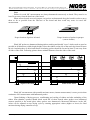
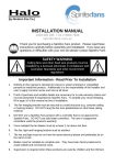
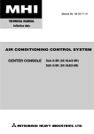
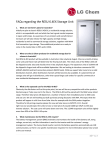
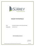
MEASUREMENT&CONTROL EQUIPMENT AND DRYING KILNS 18000 Nis, Borislava Nikolica - Serjoze 12; Phone/Fax: +381 18 211 212, 217 468; www.nigos.co.yu; [email protected] NIGOS DRYERS - WOOD DRYERS (GENERAL) - USER'S MANUAL ISO 9001 CERTIFIED NIGOS dryers MEASUREMENT&CONTROL EQUIPMENT AND DRYING KILNS 18000 Nis, Borislava Nikolica - Serjoze 12; Phone/Fax: +381 18 211 212, 217 468; www.nigos.co.yu; [email protected] INTRODUCTION Company "NIGOS - elektronik" was founded in 1990. It's main field of work is production of equipment for measurement and control systems as well as drying kilns. "NIGOS - elektronik" started with the production of power supplies, and later developed industrial counters, air temperature and relative humidity measurement equipment and other automation equipment for industry. In 1995 "NIGOS - elektronik" starts with production of wood dryers. In 1998 NIGOS engineers designed condensing (dehumidifying) dryer which was awarded with The Grand Prize "Step Into The Future" at the 42nd International Technical Fair held in Belgrade same year. Since then, NIGOS has produced a large number of automatic dryers both in country and abroad. With the equipment that NIGOS delivers and assembles, user also gets drying technology, as well as 2 years warranty for whole dryer and 5 years warranty for automatic controller unit. Material given in this document can primarily be considered as the manual for automatic dryers produced by NIGOS. Our main intention was to give some basic description of the drying process aside the dryers manual. Majority of users are already familiar with this facts, but we think that it would be good to repeat it once again. Group of authors NIGOS dryers 1 MEASUREMENT&CONTROL EQUIPMENT AND DRYING KILNS 18000 Nis, Borislava Nikolica - Serjoze 12; Phone/Fax: +381 18 211 212, 217 468; www.nigos.co.yu; [email protected] BASIC DRYING CONCEPTS In order to use wood as a production material, it is necessary that it has low water content (also known as: moisture content - MC). It means that the extra water must be extracted from the wood, and that is achieved by using the drying process. Main factors that determine wood drying are: - air temperature, - air humidity, - air circulation. It is possible to dry wood in two different ways: - natural drying, and - artificial drying. Natural drying is performed in the open, without human interference. Temperature, humidity and air circulation depend upon the climate conditions of the ambient where the wood is stored, so the drying is extremely slow, and lasts for a year or more. Artificial drying is performed in special drying chambers (kilns, dryers). Temperature, humidity and air circulation are controlled artificially. Time required for drying is reduced to several days or weeks. But, apart from reduced time of drying, there are other advantages such as: - reducing of storage space required, - required wood moisture content (MC) can be achieved accurately, - uniform quality of dried elements is achieved, etc. Further text will only address artificial drying because it has widest application. PHYSICAL CHARACTERISTICS OF AIR Main factors which affect wood drying are temperature, humidity and air circulation. Temperature and humidity change during drying process, while wanted air circulation is achieved using flow fans and is mainly constant for a specific dryer. AIR HUMIDITY Air humidity is a term which resemble existence of water vapors in air. When temperature is constant, air can absorb water vapors up to certain amount. Above it, condensing effect will occur. Air that contains maximum quantity of water vapor is called saturated air. This maximum quantity of water contained in 1 m3 of air is temperature dependant. It increases with the increase of temperature. Table: Water vapor content in air at variuos temperatures. Air temperature [ 0C ] Maximal water vapor 3 [ g/m ] 0 10 20 30 40 4,8 9,4 17,3 30,4 51,1 50 60 70 80 90 100 82,9 130,1 198,0 293,0 423,1 597,0 If saturated air is heated up, its ability to receive more water will increase, but if it is cooled down, surplus of water in air will be present and condensation will occur. This property is used for extraction of water from wood, id est its drying. NIGOS dryers 2 MEASUREMENT&CONTROL EQUIPMENT AND DRYING KILNS 18000 Nis, Borislava Nikolica - Serjoze 12; Phone/Fax: +381 18 211 212, 217 468; www.nigos.co.yu; [email protected] RELATIVE AIR HUMIDITY Relative air humidity (values are presented as %RH) is a very important variable in drying process. 3 It is a ratio of weight of water vapors in 1 m of air and maximal weight of water vapor which that air can receive at given temperature and pressure. Saturated air has relative humidity of 100%, while absolutely dry air has 0%RH. Relative humidity depends on the air temperature. For instance: if 1 m3 of air is at the temperature 0 of 40 C and has 30g of water vapor in it, then the relative humidity of such air is: (30 / 51,1) x 100 = 58,7%, where 51,1 is data from table, for air at the temperature of 40 0C. Similarly, if the same air (containing the same amount of water) is heated to 60 0C, then its relative humidity would be: (30 / 130,1) x 100 = 23% With increase of temperature, relative humidity is decreased, and vice versa - decrease of temperature leads to increase of relative humidity. Direction of natural air circulation also depends on temperature. Heated air streams upwards because it is lighter, while cold air streams downwards. While going through timber stack, air is getting colder and is streaming downwards. Also, condensation of surplus water vapor occurs. WOOD MOISTURE CONTENT (WOOD MC) Water trapped inside the wood exists in two different forms: free water and bound water. Free water is distributed in inter-cellar space. Since it is not chemically connected to wood structure, it can be relatively easy removed. Bound water is located in cell walls and is connected to wood fibre by molecular forces. This is the reason why it is much harder to remove bound water than free water from the wood. It can be removed only through evaporation process. It is determined that part of water (moisture) content in the wood above 30% is free water. Below this level of 30% wood only contains bound water. This 30% border is also known as point of saturation of wood fibres. Water in wood is known as Wood Moisture Content (MC) and is represented in %. It is a ratio of weight of water inside the wood and absolutely dry wood: V = (mV / mO) x 100 [ % ] where: V - equals wood MC in % mV - equals weight of water in gramm mO - equals weight of absolutely dry wood in gramm For instance: If we say that wood moisture content is 10%, it means that in peace of that wood which would weight 1000 g when absolutely dry there is 100 g of water. Moisture content of raw wood depends on the type of wood and can reach 200%. Average values are in range 50 ÷ 100%. Depending on the application of the wood, it should be dried to certain MC: - plywood: 5 ÷ 8% - parquet: 8 ÷ 10% - room furniture 8 ÷ 10% - garden furniture 13 ÷ 16% - joinery: 10 ÷ 12% NIGOS dryers 3 MEASUREMENT&CONTROL EQUIPMENT AND DRYING KILNS 18000 Nis, Borislava Nikolica - Serjoze 12; Phone/Fax: +381 18 211 212, 217 468; www.nigos.co.yu; [email protected] SHRINKAGE AND SWELLING OF WOOD Change of content of bound water in wood causes change of dimension of wood. When dried, the wood shrinks (decreases its dimension), and if moisturized, it swells (increases its dimension). Shrinkage is steady and linear when moisture content drops below 30% (saturation point). Level of shrinkage is specific for each wood type and is different in longitudinal and lateral direction. It can be up to 10%. The way of drying will also influence the shrinkage of wood. Naturally dried wood will shrink less then artificially dried wood. Wood dried at high temperature and relative humidity will shrink more than wood dried at lower temperature and air humidity. When dry wood absorbs water, it will increase its volume, id est starts swelling until saturation point of wood fibers is reached. Above this boundary wood will stop swelling because it can not absorb any more water. HYGROSCOPICNESS AND EQUILIBRIUM MOISTURE CONTENT Hygroscopicness is a property of material to change its moisture content under influence of surrounding air. If the wood has MC below 30% (wood fibers saturation point) it will be hygroscopic. This means that it will absorb and release moisture depending on surrounding air. The lower the MC, the higher force of absorbing water from air will be. Also, the lower relative humidity of the air will be followed by the higher force of release the water from the wood to surrounding air. This means that depending on which of these values is greater, movement of water can be from wood to air (releasing) or reverse (absorbing). When these two forces are equal, there is no movement of moisture and it is called Equilibrium Moisture Content of wood (EMC). When wood is exposed to certain conditions for a long period of time, it finally reaches the EMC. It releases or absorbs the water from the air, depending on that if its moisture is higher or lower than equilibrium. But, the wood which is once dried below its equilibrium moisture content, can never absorb the moisture to EMC exactly, but little less. This phenomenon is know as hysteresys and is approximately 1 to 2 % of MC. We emphasize that it is useless and destructive to dry wood below equilibrium moisture that is appropriate for surrounding where wood will be used. That is one reason why data regarding final moisture content for each application of wood, given in previous chapter, should be obeyed. Next table shows dependance of wood EMC (ur) of temperature and relative air humidity. Table is given according to psychrometric method, id est contains compared temperatures of wet and dry bulb. NIGOS dryers 4 20.0 19.5 19.5 19.0 18.5 18.5 18.0 18.0 18.0 17.5 17.5 17.0 17.0 16.5 16.5 15.5 15.0 14.5 13.5 13.0 12.0 11.5 10.5 10.0 9.5 98 NIGOS dryers 96 94 92 90 88 86 84 82 80 78 76 74 72 70 65 60 55 50 45 40 35 30 25 20 16.0 17.0 18.0 19.0 20.0 21.0 22.0 23.0 24.0 24.5 25.5 25.5 26.0 26.5 27.0 27.0 27.5 28.0 28.0 28.5 28.5 29.0 29.0 29.5 30.0 4.3 5.1 5.9 6.6 7.3 8.1 8.9 9.7 10.5 11.5 12.7 13.1 13.7 14.3 15.0 15.7 16.4 17.3 18.1 19.1 20.1 21.2 22.3 23.8 26.1 30.0 - Relative air humidity (%RH) 4.5 5.3 6.1 6.8 7.6 8.4 9.2 10.0 10.9 11.9 13.0 13.5 14.1 14.7 15.5 16.2 16.9 17.7 18.7 19.7 20.6 22.1 23.0 24.4 28.0 30.0 30.0 20.0 100 ur tm tm ur tS = 30 0C tS = 20 0C (%) 22.5 24.0 25.0 26.5 28.0 29.5 30.5 32.0 33.0 34.0 34.5 35.0 35.5 36.0 36.5 36.5 37.0 37.0 37.5 38.0 38.0 38.5 39.0 39.0 40.0 40.0 tm 25.5 27.0 29.0 30.5 32.0 33.5 34.5 36.0 37.0 38.5 39.5 40.0 40.0 40.5 41.0 41.5 41.5 42.0 42.5 43.0 43.5 43.5 44.0 44.0 44.5 45.0 tm 3.9 4.6 5.3 6.0 6.7 7.5 8.2 9.0 9.8 10.8 11.8 12.3 12.9 13.4 14.0 14.7 15.4 16.1 17.0 17.9 18.9 20.0 21.2 22.7 24.0 28.5 ur tS = 45 0C 28.5 30.5 32.0 34.0 35.5 37.5 39.0 40.0 41.5 42.5 44.0 44.0 44.5 45.0 45.5 46.0 46.5 47.0 47.5 47.5 48.0 48.0 48.5 49.0 49.5 50.0 tm 3.7 4.4 5.1 5.8 6.5 7.2 8.0 8.7 9.5 10.4 11.5 11.9 12.5 13.0 13.7 14.3 15.0 15.7 16.5 17.4 19.3 19.5 20.7 22.0 24.5 28.0 ur tS = 50 0C tS - Temperature of dry bulb (0C) 4.0 4.8 5.5 6.3 7.0 7.7 8.4 9.2 10.1 11.0 12.1 12.6 13.2 13.8 14.5 15.1 15.8 16.6 17.5 18.3 19.3 20.3 21.8 23.1 25.5 29.0 ur tS = 40 0C 31.5 34.0 36.0 37.5 39.5 41.0 43.0 44.0 45.5 47.0 48.0 48.5 49.0 49.5 50.0 50.5 51.0 51.5 52.0 52.5 52.5 53.0 53.5 54.0 54.5 55.0 tm 35.0 37.0 39.5 41.5 43.5 45.5 47.0 48.5 50.0 51.5 52.5 53.0 54.0 54.5 55.0 55.0 56.0 56.5 57.0 57.5 58.0 58.0 58.5 59.0 60.0 60.0 tm 3.4 4.1 4.7 5.3 6.0 6.6 7.4 8.1 8.9 9.7 10.7 11.2 11.7 12.1 12.8 13.3 14.0 14.8 15.6 16.4 17.3 18.6 19.7 21.0 23.2 26.2 ur tS = 60 0C 38.0 40.5 43.0 45.5 49.0 49.5 51.5 53.0 55.0 56.0 57.5 58.0 59.0 59.5 60.0 60.5 61.0 61.5 62.0 62.5 63.0 63.0 63.5 64.0 64.5 65.0 tm 3.2 3.8 4.4 5.0 5.8 6.3 7.0 7.7 8.5 9.4 10.3 10.7 11.2 11.7 12.3 12.9 13.5 14.3 15.0 15.9 16.8 17.8 19.0 20.5 22.8 26.0 ur tS = 65 0C tm - Temperature of wet bulb (0C) 3.6 4.2 4.9 5.6 6.2 6.9 7.7 8.4 9.2 10.2 11.1 11.6 12.0 12.6 13.2 13.8 14.5 15.3 16.0 16.9 17.8 19.0 20.0 21.7 23.9 27.0 ur tS = 55 0C 41.0 43.5 47.0 49.0 51.5 53.5 55.5 57.0 59.0 60.5 62.5 63.0 63.5 64.0 64.5 65.0 65.5 66.0 67.0 67.5 68.0 68.5 69.0 69.0 70.0 70.0 tm 3.0 46.5 51.5 56.0 57.0 60.0 62.0 64.5 66.5 68.0 70.0 71.5 72.0 73.0 73.5 74.0 74.5 75.0 76.0 76.5 77.0 77.5 78.0 78.5 79.0 80.0 80.0 tm 2.7 3.3 3.8 4.4 4.9 5.5 6.2 6.8 7.5 8.3 9.3 9.6 10.1 10.5 11.1 11.7 12.2 12.9 13.6 14.4 15.3 16.5 17.6 18.8 20.8 24.4 ur tS = 80 0C ur- Equilibrium moisture (%) 3.7 4.3 4.8 5.4 6.1 6.7 7.5 8.2 9.0 10.0 10.4 10.8 11.3 11.9 12.5 13.1 13.8 14.6 15.4 16.3 17.5 18.7 19.8 22.0 25.7 ur tS = 70 0C 18000 Nis, Borislava Nikolica - Serjoze 12; Phone/Fax: +381 18 211 212, 217 468; www.nigos.co.yu; [email protected] MEASUREMENT&CONTROL EQUIPMENT AND DRYING KILNS EQUILIBRIUM MOISTURE CONTENT TABLE (psychrometric table for wet air) 5 MEASUREMENT&CONTROL EQUIPMENT AND DRYING KILNS 18000 Nis, Borislava Nikolica - Serjoze 12; Phone/Fax: +381 18 211 212, 217 468; www.nigos.co.yu; [email protected] ARTIFICIAL DRYING OF WOOD Artificial drying of wood has a wide application in wood industry. Special chambers, known as wood dryers or kilns, are used for artificial drying of wood boards. There are several types of dryers, depending on the applied wood drying method: - conventional kilns; - dehumidifying (condensing) kilns; - vacuum kilns; - microwave kilns. Because of more complex operation and higher cost of equipment for vacuum and microwave dryers, most common dryers in use today are conventional and dehumidifying (condensing) kilns. CONVENTIONAL KILNS Conventional drying method is most commonly used today because these dryers are technically very simple, even for very large volumes (for more than 100 m3 of timber). They do not require special maintenance, and large energy consumption is reduced by using wood waste or sawdust as fuel for heating boilers. Drying is achieved by the replacement of inner damp air with outer drier one. Hot air or steam can be used as heating medium. We must point out that this type of dryer is recommended for companies which have large amount of wood waste. Main form of conventional kiln is given at the picture 1. Optimum ventilation during drying process is provided by the reversible fans mounted above the aluminum false-ceiling. These fans provide moving of air through the whole timber stack (in both directions, alternating). The air is then reheated by heaters (heat exchangers), if needed. Moisture from wood traverse into the air because of its higher temperature. When the dampers are unfolded, part of the dump air is ejected out of the kiln chamber through the open dampers (K2 or K1) carrying wood moisture with it. Simultaneously, the same amount of fresh air enters the kiln chamber through the opposite damper (K1 or K2). Fresh, dry air mixes with inner dump air, circulates through the stack, and the process is repeated (as long as the drying lasts). Equable circulation through wood stacks is achieved by mounting false-ceiling made of aluminum. Since the fresh air that enters the kiln chamber through dampers is colder (especially during winter), the heaters must work all the time to maintain requested temperature inside the chamber. Drying temperature is 80 °C maximum. It is logical to conclude that the energy consumption in this type of kiln is relatively high (80 to 200 kWh per m3 of timber, for entire drying cycle and for flow fans alone), so the energy for heating up is almost always used from the boiler. Installed power is approximately 3 to 5 kW per m3 of timber. Air velocity depends on the chosen drying regime, but is mostly around 2 m/s, except for the hard drying regimes when it can achieve up to 5 m/s. Consequently, this requires flow fans much stronger than the ones 3 used in dehumidifying kilns (their power is approximately 0,25 kW per m of timber). 1 1 2 K1 K2 4 6 3 5 1 - Servo-controlled dampers 2 - Flow fans 3 - Heat exchangers 4 - Sub-ceiling 5 - Humidifying system 6 - Substation Picture 1. Schematic presentation of conventional kiln NIGOS dryers 6 MEASUREMENT&CONTROL EQUIPMENT AND DRYING KILNS 18000 Nis, Borislava Nikolica - Serjoze 12; Phone/Fax: +381 18 211 212, 217 468; www.nigos.co.yu; [email protected] "NIGOS - elektronik" produce conventional dryers with various volume. Technical characteristics of conventional dryers are given in table below. Equipment delivered for each dryer is installed in drying chamber which can be built of bricks and concrete, or in montage chamber made of insulated panels. Electric panel is placed in convenient room. Average capacity m3 30 to 50 40 to 60 50 to 70 50 to 70 70 to 100 80 to 120 DRYER MODEL VKS-40 VKS-50 VKS-60 VKS-60A VKS-80 VKS-100 Boiler heating power kcal / h 160 000 180 000 240 000 240 000 280 000 320 000 Flow fans 5 x 630 6 x 630 7 x 630 8 x 630 9 x 630 10 x 630 Installed electrical power kW 7.5 9.0 10.5 12.0 13.5 15.0 Optimal dimensions of chamber a(m) x b(m) x h(m) 4.6 x 8.2 x 5.1 6.8 x 7.0 x 5.1 6.8 x 8.2 x 5.1 8.6 x 7.0 x 5.1 8.6 x 8.2 x 5.1 8.6 x 9.5 x 5.1 LOW-COST CONVENTIONAL KILNS These are dryers that provide high drying quality of all wood types with the least energy consumption (up to 100 kWh per m3 of timber for entire drying cycle). Air circulates in one direction only at the velocity of up to 1,5 m/s. This ensures equal drying of timber of up to 4 m. Installed power of fans is approximately 0,15 kW per m3 of timber. Depending on user demand, MC-411R, MC-502R or MC-1000 automatic control unit can be mounted. These kilns are especially convenient wherever some electrical power supply problems may occur, because they can operate on some alternative, spare power sources. 1 - Exhaust damper (flap) 2 - Intake damper (flap) 3 - Flow fans 4 - Heat exchangers 5 - Humidifying system 3 2 4 5 Picture 2. Schematic presentation of low-cost conventional kiln 1 DRYER MODEL NKS-10 NKS-20 NKS-30 NIGOS dryers Average capacity m3 8 to 15 15 to 25 25 to 35 Boiler heating power kcal/ h 40 000 80 000 120 000 Flow fans 4 x 450 4 x 560 4 x 630 Installed electrical power kW 1.6 3.0 6.0 Optimal dimensions of chamber a(m) x b(m) x h(m) 4.6 x 4.0 x 3.0 4.6 x 6.0x 4.0 4.6 x 6.5 x 5.1 7 MEASUREMENT&CONTROL EQUIPMENT AND DRYING KILNS 18000 Nis, Borislava Nikolica - Serjoze 12; Phone/Fax: +381 18 211 212, 217 468; www.nigos.co.yu; [email protected] DEHUMIDIFYING AND COMBINED KILNS Dehumidifying kilns belong to newer wood drying technologies. Condensation of water (dehumidification) is used for separating moisture from wood, without external air exchange. Our kilns are completely automated, which means that with the equipment, user also receives wood drying technology. Kiln can be constructed or assembled of aluminum bearing structure. Most important part of a dehumidifying kiln is a heat pump. Air in the kiln passes through the load of timber and absorbs moisture from the wood. Part of that air circulates through the heat pump where the moisture is condensed and drained out of the chamber. Dried, reheated air comes back to kiln chamber. Energy consumption is minimal, since there is almost no inner/outer air exchange. Air circulation in these kilns is smaller than in conventional kilns, while the electrical power of flow fans and heat pump equals approximately the power of flow fans in conventional kilns. Operating principle is given on picture 3. Automatic control unit especially designed in "NIGOS-elektronik" controls drying process. Automatic control unit has built-in programs for drying of all wood types regardless of a starting wood moisture content. It controls drying process automatically, so the operator presence is not needed during drying. Average energy consumption is approximately 30% - 60% of installed power, which is up to 1kW per m3 of timber (as shown in technical data tables below). If we monitor the whole drying cycle, energy 3 consumption is about 100 - 200kWh per m for the whole drying cycle. Larger energy consumption is only during first day of heating stage, when electrical heaters are turned on continuously until working temperature is reached. Later, during drying stage, these heaters are rarely turn on. Drying quality in dehumidifying kilns is significantly better than in any conventional kiln, because the drying is equable in the whole timber load, so there is no danger of developing degrade in the timber (cracks, checks, warping...). Drying is fast enough, since the working temperature can reach up 60 °C. These kilns are environmental friendly because all wastes that are produced during drying process are harmless for water and environment. Especially good results are achieved with drying of natural (untreated) wood (beech, ash,...). 7 8 6 5 1 4 3 1 - Heat pump (aggregate) 2 - Drain pipe 3 - Heat pump's intake opening 4 - Heat pump's output opening 5 - Atomizers 6 - Heat exchanger (for combined kiln only) 7 - Flow fans 8 - Air exchange system 2 Picture 3. Schematic presentation of dehumidifying (combined) kiln NIGOS dryers 8 MEASUREMENT&CONTROL EQUIPMENT AND DRYING KILNS 18000 Nis, Borislava Nikolica - Serjoze 12; Phone/Fax: +381 18 211 212, 217 468; www.nigos.co.yu; [email protected] Main advantages of dehumidifying kilns are: - Drying of all types of wood regardless to initial moisture content; - Excellent quality of drying because there is no cracks, checks, wrapping, discoloration (especially good results are achieved in drying of non-steamed light colored materials); - Equal drying throughout all timber stack; - Environmental friendly; 3 - Installed electrical power up to of 1 kW/ m timber; - Minimal energy consumption - no air exchange; - Average consumption 30 ÷ 50% of installed power; - Air circulation needed for operation of dehumidifying kilns is smaller then in conventional, so electrical power of installed fans is smaller; - These kilns do not require neither boiler for operation, nor an operator presence - completely automatic operation of kiln; - Drying is fast enough, because drying temperature can be up to 60 °C; - There is an option for connecting of several dryers to a single computer and remote surveillance of drying process because each controller has a communication feature. If a boiler installation exists in the drying complex, it makes sense to mount heat exchangers for hot water or steam (depending on the boiler) in the kiln. In that case, energy from the boiler could be used for heating of the drying chamber. That way kiln becomes combined (automatically uses boiler heat). This option is interesting only for a large capacity kilns and in cases where electrical power supply is unstable (large voltage or current oscillation, or frequent power cut-downs during winter periods). Drying in that case is performed in conventional way, heat pump is turned-off, and electrical energy is used only for flow fans. Main characteristics of combined kilns are: - Electrical heater are not used for heat-up phase and additional heating; - In case of bad or unstable electricity supply, dryer can operate in purely conventional fashion. Additional power source (aggregate) can be used for fans operation in case of power failure; - When absolutely wet timber is loaded, this type of dryers increases drying speed. Combined kiln unites good characteristics of both dehumidifying and conventional kiln. That provides the greatest drying quality with the least energy consumption for the shortest time. APPROXIMATE TIME OF DRYING FOR DIFFERENT TYPES OF TIMBER TYPE OF WOOD Oak Ash Beech Birch, Poplar Pine, Fir, Juniper DRYING IN DAYS FROM 70% TO 10% AND FROM 40% TO 10% OF WOOD MOISTURE CONTENT FOR VARIOUS TIMBER THICKNESS 25mm from 70% from 40% to 10% to 10% 20 13 15 10 10 7 6* 4* 6* 4* 38mm from 70% from 40% to 10% to 10% 35 22 25 15 16 11 11 8 9 7 50mm from 70% from 40% to 10% to 10% 52 32 38 24 25 16 14 10 12 9 70mm from 70% from 40% to 10% to 10% 75 52 60 42 41 28 21 14 18 13 Note: Times marked with * can be achieved in combined kilns only NIGOS dryers 9 MEASUREMENT&CONTROL EQUIPMENT AND DRYING KILNS 18000 Nis, Borislava Nikolica - Serjoze 12; Phone/Fax: +381 18 211 212, 217 468; www.nigos.co.yu; [email protected] "NIGOS - elektronik" produce drying kilns of various volumes. The most optimal kilns are for 20 ÷ 100 m . Equipment, delivered for each kiln, is installed in the chamber which can be built of bricks and concrete or made of insulating panels. Electric panel is placed outside the dryer in a convenient room. 3 The equipment for each dryer consist of: - heat pump (their number and type depend on the size of dryer), - electrical heaters, - flow fans (circulation fans), - air exchange system (exhaust damper with fan, intake damper), - power electric panel (KRO), - automatic control unit, - set for temperature, EMC, wood MC measurement (connection boxes, probes, cables, etc), - humidifying system (filter, electromagnetic valve, atomizers, tubes, etc) - hot water / steam heat exchanger (for combined kilns). MODEL SU[ARE Type of dryer Volume Heat pump Circulation fans Air exchange system Power electric panel Automatic control unit Set for temperature, EMC, wood MC measurement Wood MC measurement Humidifying system Heat exchanger (option for combined kiln) Installed power Average consumption Dimensions W(m) x D(m) x H(m) NIGOS dryers NIGOLUX-12 NIGOLUX-20 NIGOLUX-30 NIGOLUX-40 NIGOLUX-60 NIGOLUX-80 Dehumidifying / Dehumidifying / Dehumidifying / Dehumidifying / Dehumidifying / Dehumidifying / Combined Combined Combined Combined Combined Combined 3 3 3 3 3 8 15m 15 25m 25 35m 30 50m 50 70m 70 100m3 1 x TP-12 1 x TP-20 1 x TP-30 2 x TP-20 2 x TP-30 3 x TP-30 1.6 kW 3.0 kW 6.0 kW 9.0 kW 12.0 kW 13.5 kW Yes Yes Yes Yes Yes Yes KRO-12 KRO-20 KRO-30 KRO-40 KRO-60 KRO-80 MC - 411R MC - 900R MC - 900R MC - 900R MC - 900R MC - 900R 1 set 1 set 1 set 1 set 1 set 1 set at 4 points at 6 points at 6 points at 6 points at 6 points at 6 points Yes Yes Yes Yes Yes Yes Yes Yes Yes Yes Yes Yes app 10 kW app 18 kW app 24 kW app 36 kW app 48 kW app 70 kW 4 kWh 8 kWh 11 kWh 16 kWh 22 kWh 32 kWh 4.6 x 4.0 x 3.0 4.6 x 6.0 x 4.0 4.6 x 6.5 x 5.1 6.8 x 7.0 x 5.1 8.6 x 7.0 x 5.1 8.6 x 8.2 x 5.1 10 MEASUREMENT&CONTROL EQUIPMENT AND DRYING KILNS 18000 Nis, Borislava Nikolica - Serjoze 12; Phone/Fax: +381 18 211 212, 217 468; www.nigos.co.yu; [email protected] KILN’S CHAMBER For proper operation of equipment, drying quality and optimal energy consumption, the most important factor is the kiln’s chamber. It can be made of bricks and concrete or pre-fabricated insulating panels. Basically, chamber must be erected on firm foundation, it’s construction must be very rigid, hydro and temperature well insulated and with convenient doors. KILN’S FLOOR Aside good insulation, kiln’s floor must be able to support high weights. If manual stacking of timber is used, floor must be able to endure a minimum of 2 t/m2. If a fork-lifter is used this tonnage must be at least twice or more bigger. New floor is best prepared in following way: - foundation made of 20 cm of pebble, - concrete layer 15 cm thick, - hydro-insulation: condor, - thermo-insulation: hard-pressed styropor 3 cm thick, - PVC foil, - strong reinforced concrete 8 ÷ 10 cm thick for fork-lifter stacking; 5 ÷ 8 cm thick for manual stacking, - floor must have a pitch in direction to draining hole (0,5 ÷ 1 %). KILN’S WALLS Kiln’s walls are made of quality bricks or construction blocks 24 cm thick. Best for use are syporex blocks 20 cm thick. Outside walls are covered with plain or cement mortar. Inside of walls must be well insulated. One of cheaper way of thermo-insulation is: - styropor 5 cm thick; - PVC foil; - Al sheet 0,5 ÷ 0,8 mm thick. KILN’S CEILING Ceiling can be made of concrete or wooden beams. Insulation of the ceiling should be same as the walls, only at least 50% thicker unless there is another room above. KILN’S DOOR Doors are the most critical element of kiln’s chamber because they must provide easy operation and opening, with good insulation. The best solution is if they are made of 80 mm thick insulated aluminum coated panels with foamed polyurethane. Rubber gaskets are put on the both side of the doorframe to ensure the total sealing. The main door can be winging or sliding with special type with a mechanism for opening and closing. Every kiln is provided with an inspection door. Dimension, positioning and opening of the doors depend on chamber type and timber stacking method. Inspection door is used for service of equipment and checking of the timber and conditions inside the chamber, without opening the main door while drying is in progress. This way it is possible to access the chamber during operation without great loss of energy caused by opening of main doors. They must provide opening mechanism from inside the chamber. NIGOS dryers 11 MEASUREMENT&CONTROL EQUIPMENT AND DRYING KILNS 18000 Nis, Borislava Nikolica - Serjoze 12; Phone/Fax: +381 18 211 212, 217 468; www.nigos.co.yu; [email protected] USER'S MANUAL NIGOS dryers MEASUREMENT&CONTROL EQUIPMENT AND DRYING KILNS 18000 Nis, Borislava Nikolica - Serjoze 12; Phone/Fax: +381 18 211 212, 217 468; www.nigos.co.yu; [email protected] CUSTOMER OBLIGATIONS AND STEPS REQUIRED BEFORE START OF EACH DRYING CYCLE, DURING DRYING AND AT THE END BEFORE THE START OF EACH DRYING CYCLE: 1. Sweep the chamber to remove any saw dust, wood particles etc which might clog drain pipe, heat exchangers and heat pump. 2. Check installed equipment and verify it is working properly. 3. Stack up the timber inside the chamber. 4. Set up wood MC probes in the timber and plug them in connection boxes. 5. Close the main door. Make sure they fit the frame good to provide good sealing. 6. Turn on the power electric board and automatic control unit. 7. Set up required parameters on the automatic controller which depend on the specific timber loaded in the chamber (wood type, mode of operation, board thickness, final moisture content, cooling temperature, conditioning). 8. Set up all wood probes in active state. 9. Start the drying. DURING DRYING: Check the automatic controller few times a day to see if certain warning or alarm situation have occurred. Controller will try itself to solve the problem by adjusting outputs for temperature / cooling / drying. If any of these situation is present for long time, try to find the cause of the problem. If you are unable to do that, contact NIGOS - elektronik. END OF DRYING: 1. Slightly open main doors. The timber needs to cool down gradually to avoid cracking due to high temperature difference between the chamber and outside air. 2. After 10 to 12 hours open main doors. 3. Unload the chamber and store dried timber in appropriate (closed) storage space, or proceed with further processing. NIGOS dryers 12 MEASUREMENT&CONTROL EQUIPMENT AND DRYING KILNS 18000 Nis, Borislava Nikolica - Serjoze 12; Phone/Fax: +381 18 211 212, 217 468; www.nigos.co.yu; [email protected] SETTING UP THE WOOD MC MEASUREMENT PROBES Drying process is primarily based on average wood MC that is obtained from 6 different measuring points. That is why proper fitting of the probes in the wood and their symmetrical disposition inside the chamber is most important. Wood probes are made of stainless steel. They should be taken out of timber after each drying cycle, and saved for later use. Each MC probe has one pair of stainless steel nails as shown on the picture. Recommended lengths of nails are: - 30 mm - used for lumber up to 40 mm thick (thin lumber) - 45 mm - used for lumber above 40 mm thickness (thick lumber) One pair of probes is used for each MC measurement point. Probes are hammered in the lumber perpendicularly to board at distance of 30 to 35 mm (optimum distance is 32 mm) between them. A pair of holes Ø3.2 (3 ÷ 3.5) mm should be drilled in the lumber before hammering the probes. Depth of these holes should be 15 mm smaller than the probes' length. Probes should be than hammered into the holes whit paying attention that the depth of penetration must not be smaller than 1/3 of board depth (1/2 of board depth is best). In case when thin and soft lumber is used, user does not need to drill holes, but he can hammer the probes directly into the lumber. Picture shows example of the wood probes fitting. Probe cable is connected on the other side to the patch board (DS-04) placed on the wall, inside the drying chamber. ETF - K 2 x 0,75mm2 Wood MC probe UGL 17 ÷ 25 mm 50 mm Wood MC probe connection cable BH2 BH3 BH4 BH5 DS-06 30 ÷ 35 mm NIGOS dryers BH1 LIYCY 10x0.25mm2 -T BH6 RG-58 13 MEASUREMENT&CONTROL EQUIPMENT AND DRYING KILNS 18000 Nis, Borislava Nikolica - Serjoze 12; Phone/Fax: +381 18 211 212, 217 468; www.nigos.co.yu; [email protected] Note: Probes for wood MC measurement are always hammered transversely to board. They must be at least 50 cm away from the head-cut of the board. When narrow boards are used (parquet, etc) probes are hammered along the board in order to move them as far as possible from the side-cuts of the board and thus avoid any errors in wood MC measurement. probe be pro ut d-c a e h min 50 cm Proper location of probes in board Proper location of probes in parquet (narrow boards) S1 S5 S1 S3 S5 S3 S4 S4 S6 S6 S2 min 50 cm height of the stack Wood MC probes are hammered during timber stacking and should "cover" whole stack as equal as possible in all directions (width, depth, height). Since the timber on the side of the stack dry fastest because the air circulating there is driest and fastest circulating, probes should be located at least 50 cm away from all sides of the stack. Following picture shows minimal distances from the sides of the stack. S2 depth of the stack min 50 cm min 50 cm width of the stack min 50 cm Wood MC measurement with portable moisture meter (instant measurement) is more precise than continuous MC measurement with hammered probes. Upon finishing of drying process, conditioning and cooling of timber and after unloading of the timber from chamber, operator should check wood MC of those boards where probes were hammered (nearest possible to the actual place where probes were hammered). Measured differences in the MC values can be adjusted at next drying cycle by entering appropriate values (higher or lower) for final moisture during drying controller set-up. NIGOS dryers 14 MEASUREMENT&CONTROL EQUIPMENT AND DRYING KILNS 18000 Nis, Borislava Nikolica - Serjoze 12; Phone/Fax: +381 18 211 212, 217 468; www.nigos.co.yu; [email protected] TIMBER STACKING (PILING UP) The way in which the timber is stack influence in major the quality of drying. It often happens that unprofessional and un-appropriate stacking of timber leads to low quality of dried material. The basic principle of artificial drying is that boards must be placed in such fashion that the surface of the board must have biggest possible surface open (in contact with surrounding air). In order to meet this request, different types of stacks are made for different types and dimensions of the boards. In cases where cut boards are dried, there are 2 different types of stack depending on the type of the wood. Conifer trees boards usually have equal length and therefor can be stacked like shown on the picture 1.a). Boards cut from deciduous trees have different lengths and must be stacked like shown on the picture 1.b). Uncut boards can not be stacked without making horizontal and perpendicular spacing between boards which reduce the total volume of dryer. If boards are thicker then 60 mm (especially hard wood boards), it is good to leave horizontal spacing (2 to 3 cm) between boards to make circulation of the air possible as shown on the picture 2.b) regardless of the type of the boards (cut or uncut). a) b) Picture 1.: Schematic representation of stacking of conifer (a) or deciduous (b) boards a) b) Picture 2.: Stacking of boards without horizontal spacings a) and with horizontal spacings b) Crossbars are placed between each layer of boards to provide vertical spacings. Thickness of the crossbars depends on the thickness of the boards. Thinner boards require thinner crossbars (and smaller vertical spacing) and vice versa. Optimal thickness of the crossbars can be calculated according to: s = 10 + 0.3 x d (mm) where: s - equals thickness of crossbars in mm, and d - board thickness in mm. It is best to choose the thickness of crossbars equal to half of the thickness of boards. Since it is very unpractical to keep different sized crossbars it is best to choose following dimensions: 15 mm for boards 30 mm thick (thin boards) 25 mm for boards 31 to 60 mm thick (average boards) 40 mm for boards thicker than 60 mm (thick boards) Note: When Oak boards are dried we recommend even thicker crossbars than this ones. NIGOS dryers 15 MEASUREMENT&CONTROL EQUIPMENT AND DRYING KILNS 18000 Nis, Borislava Nikolica - Serjoze 12; Phone/Fax: +381 18 211 212, 217 468; www.nigos.co.yu; [email protected] Crossbar width should be at least 1 cm greater then it's height, and the length should match the width of the stack. Crossbars are mainly made of conifer trees, seldom of Beech or Poplar. They must not be made of Oak because they will cause change of color everywhere they touch boards. Also, crossbars must be made of physiologically healthy material to avoid transfer of disease form the crossbars to healthy boards. Horizontal spacing between crossbars depend on thickness of the boards - thinner boards request smaller spacing to avoid bending while thicker boards can sustain larger spacings. Deciduous boards request smaller spacing than conifer boards. We recommend following spacings for different thickness of boards: 90 cm for boards thicker than 50 mm 60 cm for boards 30 to 50 mm thick 50 cm for boards 25 to 30 mm thick If the boards are thinner than 25 mm and has a tendency of bending, spacing between crossbars should not exceed 40 cm. It is very important to place crossbars in straight line one on top of another to avoid bending and permanent deformation of boards (picture 3.b)). a) b) Picture 3. Crossbars layout in stack: a) regular placing, b) irregular placing In order to ensure quality drying and good air circulation front and lateral sides of the stack must be well aligned. Boards must not protrude outside the stack because it will prevent good air circulation which will result in unequal drying of timber in the stack. When unequally cut boards are stacked, longest boards are placed aligned on the outer side of the stack, and shorter ones are placed between them with head-cuts aligned with head side of the stack. air b) NIGOS dryers Head side a) Head side circulation c) Picture 4. Schematic representation of aligned a) and unaligned b) boards and influence of the unaligned boards on the air circulation (c) 16 MEASUREMENT&CONTROL EQUIPMENT AND DRYING KILNS 18000 Nis, Borislava Nikolica - Serjoze 12; Phone/Fax: +381 18 211 212, 217 468; www.nigos.co.yu; [email protected] When complete stack is placed on a wagon the length of the stack must be equal to the length of the wagon. Picture 5. shows an examples of regular and irregular placement of timber stack on the wagon. Picture 5.a) shows proper selection of the wagon and placement of boards. Picture 5. b) shows inappropriate selection of the wagon compared to length of the boards. Picture 5. c) shows irregular placement of the crossbars (unequal horizontal spacing). a) b) Picture 5.: Regular placement (a) and irregular placement (b and c) of the stack on the wagon c) Before the boards are stacked into a timber stack all sawdust must be removed from them to prevent inserting the sawdust into the drying chamber. Sawdust must be mechanically removed from the boards outside the chamber. NIGOS dryers 17 MEASUREMENT&CONTROL EQUIPMENT AND DRYING KILNS 18000 Nis, Borislava Nikolica - Serjoze 12; Phone/Fax: +381 18 211 212, 217 468; www.nigos.co.yu; [email protected] Charging of the kiln Frontal side of stack Heat pump max 20 cm min 1/6 of stack’s height Frontal side of stack min 50 cm Frontal side of stack Lateral side of stack In order to provide good air circulation inside the kiln, it is necessary to leave a sufficient distance between the back wall and the timber stack (50 cm minimum) and between lateral surface of the stack and wall of the kiln as well. The greater the stack, the greater distance between the wall and lateral surface should be provided. In practice, 1/6 of height of stack is taken as minimal distance. However, distance between frontal surfaces of stack and walls should be as little as possible. If the distances are greater than 20cm, a partition should be mounted between floor and fan carrier to prevent air circulation through those empty spaces, since that unwanted circulation decreases the main circulation through the stack, which causes worse drying of min 50 cm Heat pump Charging of the kiln can be performed manually or by using either fork-lifter or wagon. In case of manually charging or by fork-lifter, before performing that operation it is needed to place wood-beams on the floor inside the kiln (beams are 10 x 10 cm cross section), at reciprocal distance that is given in table 1. Lateral side of timber stack max 20 cm min 1/6 of stack’s height Heat pump Heat pump Heat pump Heat pump Wood beams The height of the stack should correspond to altitude of fan carriers. In the opposite, a screen should be mounted between stack and fan-carrier to prevent irregular circulation. Slightly less amount of timber can be charged in the kiln than its capacity, but not less than 70% of maximum capacity. In case the actual amount of timber is less than 70% of kiln capacity, "empty rooms" should be avoided during charging, to prevent both bad circulation through the stack and slower drying. Some examples of similar charging are given on picture 6. a) b) Picture 6. Correct (a) and false (b) kiln charging NIGOS dryers 18 MEASUREMENT&CONTROL EQUIPMENT AND DRYING KILNS 18000 Nis, Borislava Nikolica - Serjoze 12; Phone/Fax: +381 18 211 212, 217 468; www.nigos.co.yu; [email protected] A FEW PRACTICAL ADVISES A stack of lumber formed for drying should consist of identical timber according to: a) moisture content of individual boards, b) thickness of boards, c) type of wood. If the stack consists of identical lumber, the drying is the fastest and the best in general. But, in practice is often necessary to form a stack that is made of dissimilar lumber (better exploitation of the kiln, production needs, etc.) If the stack consists of lumber that is identical by both thickness and type of wood, but different in moisture content in individual boards (difference is 20% or greater), then damper lumber should be placed near lateral sides of the chamber and in the upper part of stack (near the top). It’s because the air circulation is more intensive through these parts of the stack than through the other parts, so the lumber is getting dried faster. Probes for measurement of moisture content in the wood should be hammered in a larger number in damper boards. If boards are from same type of tree, but different thicknesses are used, larger number of wood probes should be hammered in thicker boards. Drying process should also be controlled according to moisture content of the thicker boards. This will slow down drying process a little, but it is more secure way of drying in order to avoid any damage on the thicker boards which could develop if drying process would be controlled according to moisture content of thinner boards. For instance, if timber stack consists of mixed conifer boards with medium thickens (30 to 60 mm) and thick boards (thicker than 60 mm) then automatic control unit should be set up for drying of conifer boards that are more then 60 mm thick. If stack consists of soft wood boards (conifer, lime, poplar) which are 25mm and 50mm thick, then two 25mm boards should be stacked in pairs, one on top of another (this way they will form a 50mm thick composition of boards), and controller should be set up for drying of boards with thickness in range 30 to 60mm. It is common practice to stack two 25mm conifer boards in "sandwich" (always in fact - even when whole stack consists of 25mm boards) and dry according to program for 50mm thick boards. This kind of stacking can not be used for any other type of tree, but instead each raw of boards must be separated with crossbars. Charging the kiln with different types of wood in the same time should always be avoided. If necessary, try to mix only types of trees that have similar hardness. In that case, drying process control should be performed according to hardest of the mixed trees. NEVER mix Oak with any other type of tree during drying. It is also not recommended to have different thickness of Oak boards in same stack. stack should consist of the boards with same thickness, otherwise, drying period can be significantly longer. DRIED TIMBER STORAGE Storage dried timber in a closed room without either crossbars or spacing between boards. Provide heating up of this room during winter. It is not recommended to storage dried timber in the open. Moisture content in dried timber can significantly increase if these instructions are not followed. NIGOS dryers 19