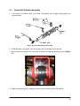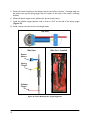
1
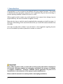
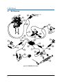
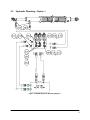
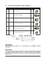
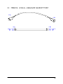
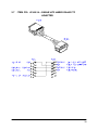
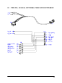
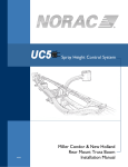
Spray Height Controller HD08A HARDI TerraForce AR Installation Manual Printed in Canada Copyright 2011 by NORAC Systems International Inc. Reorder P/N: UC5-BC-HD08A-INST Rev C (HARDI TerraForce AR) NOTICE: NORAC Systems International Inc. reserves the right to improve products and their specifications without notice and without the requirement to update products sold previously. Every effort has been made to ensure the accuracy of the information contained in this manual. The technical information in this manual was reviewed at the time of approval for publication. Contents 1 Introduction.....................................................................................................1 2 General UC5 System Layout.........................................................................2 3 Kit Parts ...........................................................................................................3 4 Ultrasonic Sensor Installation .......................................................................8 5 Module Installation ...................................................................................... 10 6 Hydraulic Installation .................................................................................. 16 7 Connecting the Sensors to the CANbus ................................................... 22 8 Software Setup............................................................................................. 23 9 Cable Drawings ............................................................................................ 24 1 Introduction Congratulations on your purchase of the NORAC UC5 Spray Height Controller. This system is manufactured with top quality components and is engineered using the latest technology to provide operating reliability unmatched for years to come. When properly used the system can provide protection from sprayer boom damage, improve sprayer efficiency, and ensure chemicals are applied correctly. Please take the time to read this manual completely before attempting to install the system. A thorough understanding of this manual will ensure that you receive the maximum benefit from the system. Your input can help make us better! If you find issues or have suggestions regarding the parts list or the installation procedure, please don’t hesitate to contact us. Every effort has been made to ensure the accuracy of the information contained in this manual. All parts supplied are selected to specially fit the sprayer to facilitate a complete installation. However, NORAC cannot guarantee all parts fit as intended due to the variations of the sprayer by the manufacturer. Please read this manual in its entirety before attempting installation. 1 2 General UC5 System Layout Figure 1 illustrates the general layout of the UC5 system components: Figure 1: General UC5 System Layout 2 3 Kit Parts 3.1 Kit Overview Figure 2: HD08A System Parts 3 3.2 Hydraulic Plumbing – Option 1 Figure 3: HD08A Hydraulic Plumbing Option 1 4 3.3 Hydraulic Plumbing – Option 2 Figure 4: HD08A Hydraulic Plumbing Option 2 5 3.4 List of Parts (Order according to Item Number) Item Part Number Name Quantity B05 44706-01 KIT CABLE TIE BLACK 10 PCS 21 IN 150 PCS 7.5 IN 1 B11 44743 MOUNTING BRACKET MAIN LIFT SENSOR UC4 PLUS 1 C01 43220-01 CABLE UC5 NETWORK 14 AWG 1M 1 C02 43220-10 CABLE UC5 NETWORK 14 AWG 10M 1 C04 43210-01 CABLE UC5 NETWORK 18 AWG 1M 5 C05 43210-20 CABLE UC5 NETWORK 18 AWG 20M 2 C10 43230-04 CABLE UC5 VALVE 2PIN DT TO 2PIN DT 6 C20 43240-30 CABLE UC5 BC HARDI DAH09 1 C35 43240-34 CABLE UC5 HARDI DAH09 TF ADAPTER 1 E01 43710 UC5 CONTROLLER MODULE 1 E02 43720 UC5 VALVE MODULE 1 E03 43732 UC5 INPUT MODULE PASS THRU 1 E05 43750 UC5 ULTRASONIC SENSOR 4 E11 43765 UC5 NETWORK COUPLER 8-WAY 1 E12 43764 UC5 NETWORK COUPLER 2-WAY 4 E20 43764T UC5 NETWORK COUPLER 2-WAY WITH TERMINATOR 2 H10 44865-60 HYDRAULICS FITTING KIT - HD08A 1 H20 44752-C3 LINEAR ROLL CYLINDER 8IN 1 M02 UC5-BC-HD08A-INST MANUAL INSTALLATION UC5 HARDI TERRAFORCE AR 1 P01 106034 UC5 NETWORK 2 PIN PLUG 2 P02 106035 UC5 NETWORK 12 PIN PLUG (A-KEY) 1 P03 106162 UC5 NETWORK 6 PIN PLUG 3 V01 44960D VALVE BLOCK ASSEM 3 STATION CC/LS PROP DT 4 BOLT 1 6 3.5 Hydraulic Fitting Kit Details (P/N: 44865-60) Item Part Number Name F01 44906 ORIFICE INSERT .0625 IN 2 F02 501301 MALE ADAPTER - 6MB 6MBSPP 8 F03 104369 PLUG - 6MBP 2 F04 44935 ORIFICE INSERT .042 IN ONE WAY 1 F05 44917 MALE TO MALE ADAPTER - 6MB 6MOR 8 F06 44928 ORIFICE INSERT .047 IN ONE WAY 1 Fitting Name Example: Quantity Picture 6 M B - 6 M OR X 90 SIZE IN 1/16TH'S GENDER: MALE OR FEMALE TYPE: B - ORB J - JIC OR - FLAT FACE P - PIPE 90° ANGLE SWIVEL TYPE GENDER SIZE The use of dielectric grease is not recommended on any NORAC electrical connections. To ensure all stainless steel hardware does not gall or seize apply a light coating of the supplied Permatex Anti-seize grease to all threaded parts upon installation. Permatex Anti-seize lubricant is preferred, but other similar anti-seize products may be used. 7 4 Ultrasonic Sensor Installation 4.1 Ultrasonic Sensor Serial Number Arrangement When installing the UC5 sensors, start with the smallest serial number on the left-hand side, and proceed to the largest serial number on the right hand side. Each UC5 sensor has a serial number stamped on the sensor housing. Apply a light coating of the supplied Permatex Anti-seize grease to all threaded parts upon installation. Figure 5: Four Sensor Serial Number Arrangement Figure 6: Sensor Mounting 8 4.2 Main Lift Sensor Installation The general mounting rule for UC5 ultrasonic sensors must be followed for the main lift sensor. Figure 7: Main Lift Bracket Assembly 1. The Main Lift bracket may need to be cut down for this installation. See Figure 8. 2. Mount the ML bracket (Item B11). Ensure sensor cable is routed properly and securely fastened. 3. Mount the Ultrasonic sensor to the bracket. Ensure the sensor has a clear view of the ground. Ensure sensor cable is securely fastened with cable-ties. Cut 4” (102mm) off of tube Cut 1-2” (2550mm) off of tube Figure 8: Main Lift Bracket Installed 9 5 Module Installation An optional module mounting bracket kit is available for purchase from NORAC. The mounting brackets are compatible with control modules and input modules. One kit is needed per module. Item Part Number Name B20 43708 UC5 MOUNTING BRACKET KIT (CONTROL AND INPUT MODULES) 5.1 Quantity 1 Control Module 1. Refer to Figure 1 and Figure 9. 2. Securely mount the control module (E01) on the sprayer, within reach of the display terminal connections, using screws, cable ties or optional brackets. 3. Connect the display terminal to the control module using the display CANbus cable. This cable must be connected to the end of the control module with only one Deutsch connector. 4. Route cable C02 from one of the control module CAN connectors towards the valve block. This will connect to the valve module. 5. Route cable C01 from the other CANbus connector towards the DAH09 enclosure. This will connect to the input module. Figure 9: Control Module Mounting 10 5.2 Valve Module 1. Install the valve module (E02) to the top of the NORAC valve block. Orient the 6-pin Deutsch (CANbus) connectors towards the P and T ports with the label facing up. Output Number 1 2 3 4 5 6 7 8 Normal Function Left Up Left Down Right Up Right Down Option 1 Option 2 Roll CW Roll CCW Figure 10: Valve Module 2. Verify the valve coil connectors are oriented vertically (Figure 11). Figure 11: Align Coils 3. Place the valve module between the valve coils. Slide a valve mounting bracket over the connectors of the valve module and the valve coil connectors. This may require flexing the plastic bracket slightly (Figure 12). 4. Ensure the bracket is pushed over the connectors far enough to allow the clips to engage behind the valve connectors. 11 Figure 12: Valve Module Bracket Installation 5. Connect the valve module CANbus to cable C02 from the control module. Route cable C04 from the other CANbus connector to the 8-way coupler. 6. With the valve module securely mounted to the valve block, connect the valve cables (C10), to the valve coils. Insert the 2-pin plugs (P01) into the unused 2-pin connectors on the valve module. 7. Connect the temperature probe to the valve block using the supplied 3/8” x 1/2” hex bolt. Tank Port 3rd Station Ports Pressure Port Right Tilt Ports Left Tilt Ports Figure 13: Valve Module - Valve Coil Connections 12 5.3 Input Module 1. Install the input module (E03) on the boom near the enclosure that houses the HARDI DAH09 PCB. Secure it to the boom using cable ties or optional brackets. 2. Connect the free end of the CANbus cable (C01) from the control module to the input module. 3. Connect cable C35 to the 12 pin Deutsch connector of C20. Connect the other end of C35 to the Thru 2 connector on the side of the input module. 4. Connect the remaining connector on C20 to the Thru 1 connector on the input module. 5. Insert the 12 pin plug (P02) into the OEM 3 connector on the input module. Figure 14: Input Module Connections 6. Run the DB15 connector and the wires with the spade connectors of C12 to the DAH 09 PCB by passing it through a hole in the enclosure. Seal the hole using the weather-proof strain relief fitting. 7. Connect the DB15 connector of cable C12 to the DAH09 DB15 connector. 8. Connect the red wire with spade connector on C12 to the Switched 12VCC on the DAH09 board (Figure 15). 9. 13 Connect the black wire with spade connector on C12 to the GND on the DAH09 board (Figure 15). Autoheight PCB Ground +12V DB15 DIP Switches Figure 15: HARDI DAH09 Connections 10. Set the DIP switches as shown in Figure 16. . Figure 16: Settings for DIP Switches 14 5.4 Optional Switch Box An optional remote switch box is available if you would like to manually control the roll function and auto/manual function from a switch in the cab. The switch box and cable can be ordered using the following part numbers: Item Part Number Name Quantity C25 44602-01 BOX SWITCH UC4 REMOTE HAND CONTROL VER.1 RMR 1 C26 43240-26 CABLE UC5 SWITCH BOX 1 C27 44658-98 CABLE UC4 3M EXTENSION 16-PIN AMP 1 1. Disconnect the connector from cable C20 that is installed in the Thru 1 connector on the input module. Remove the wedge from the face of the 12 pin Deutsch connector on C20. The wedge is removed by inserting a small flat implement underneath the wedge and lifting it up. 2. Remove the pin in position 2 and replace it with the Roll CW pin from C26. Remove the pin in position 5 and replace it with the Roll CCW pin from C26. Insert the wedge back into the plug. Connect the connector to the Thru 1 connector on the input module. 3. Remove P02 from the OEM 3 connector. Connect the 12 pin Deutsch plug on C26 to the OEM 3 connector on the input module. Route the other end of the cable to the hitch of the sprayer. 4. Attach the switch box (C25) inside the cab and connect it to cable C26. An extra label is provided with the switch box if you prefer to remove the switches from the housing and mount them in the existing sprayer switch panel. * Some sprayer types may not use all the switch functions. Figure 17: Switch Box Installation 15 6 Hydraulic Installation Ensure all pressure has been bled from the system before disconnecting any lines or fittings. Hydraulic pressure will exist on the wing tilt circuits unless the wings are being supported by other means. You may wish to perform the hydraulic installation with the wings in transport position, resting on the ground or with the tilt cylinders fully extended. Component failure due to oil contamination is not covered under the NORAC UC5 system warranty. It is recommended that a qualified technician perform the hydraulic installation. 6.1 Valve Assembly 1. On a clean surface remove the plastic plugs from the block. 2. Install two 3/8” x 1/4” BSPP (F02) or 6MB 6MOR (F05) fittings into the P and T ports on the NORAC block. Tighten to 18 ft-lbs (24 Nm). 3. Insert the two orifices (F01) into the “B” ports. 4. Install two 3/8” x 1/4” BSPP (F02) or 6MB 6MOR (F05) fittings into the “B” ports on the NORAC block. Tighten to 18 ft-lbs (24 Nm). 5. Install the 6MBP (F03) plugs into the “A” ports on the NORAC block and tighten to 18 ftlbs (24 Nm). 6. Install the orifice (F04) into the “B” port of third station of the NORAC block. 7. Install the orifice (F06) into the “A” port of third station of the NORAC block. 8. Install two 3/8” x 1/4” BSPP (F02) or 6MB 6MOR (F05) fittings into the “A” and “B” ports of the 3rd station on the NORAC block. Tighten to 18 ft-lbs (24 Nm). Figure 18: NORAC Valve Block Details 16 6.2 Valve Block Mounting 1. Mount the valve block on the center section of the boom as illustrated in Figure 19. 2. Mount the bracket onto the boom and mount the block to the bracket. Figure 19: Valve Block Mounting 17 6.3 Linear Roll Cylinder Assembly 1. In the linear roll cylinder crate is the linear roll cylinder, boom target, spring target, and sensor bracket. Figure 20: Linear Roll Cylinder Assembly 2. Install the linear roll cylinder onto the sprayer with the damper end at the top. 3. Be sure there are washers on both sides to allow the spherical bearings to pivot (Figure 21). Figure 21: Linear Roll Cylinder Mounting 4. Align the spring target by rotating the metal casing around the linear roll cylinder. 18 5. Mount the sensor bracket to the damper end (the end with no hoses). A straight edge can be used to line up the spring target with the center of the hole on the sensor mounting bracket. 6. Mount the boom target to the cylinder end (the end with hoses). 7. Install the cylinder target (bottom rod) so that it is 5/8” to the side of the spring target (Figure 22). 8. Install a sensor onto the sensor mounting bracket. Top View Side View Side View - Installed Sensor Mount Spring Target Cylinder Target Figure 22: Linear Roll Cylinder Target Alignment 19 6.4 Hydraulic Plumbing – Option 1 Hydraulic Plumbing - Option 1 requires the optional switch box for manual control of the Linear Roll functions. From this point on in the installation the booms will be inoperative until the hydraulics are fully installed. 1. After the valves are mounted on the sprayer, the hydraulic hoses and fittings can be installed (plumbed). 2. Install tee fittings on the TR and TL port fittings at the HARDI block. 3. Connect pressure and tank lines to the HARDI block (P1 & T1). Connect the other end of the hoses to the NORAC block. 4. Connect the “B” line hoses to TL1 and TR1 port fittings at the HARDI block. Connect the other end of the hoses to the NORAC block. 5. The “A” ports on the NORAC block are plugged. 6. Connect hoses to the linear roll cylinder using two 3/8” x 1/4” BSPP (F02) or 6MB 6MOR (F05) fittings. 7. Connect the hose from the port on the barrel of the linear roll cylinder to the “B” port of the 3rd station of the NORAC block. 8. Connect the hose from the port on the rod of the linear roll cylinder to the “A” port of the 3rd station of the NORAC block. 20 6.5 Hydraulic Plumbing – Option 2 Hydraulic Plumbing - Option 2 allows for manual control of the Linear Roll functions through the HC6500 joystick controls. From this point on in the installation the booms will be inoperative until the hydraulics are fully installed. 1. After the valves are mounted on the sprayer, the hydraulic hoses and fittings can be installed (plumbed). 2. Install tee fittings on the TR and TL port fittings at the HARDI block. 3. Connect pressure and tank lines to the HARDI block (P1 & T1). Connect the other end of the hoses to the NORAC block. 4. Connect the “B” line hoses to TL1 and TR1 port fittings at the HARDI block. Connect the other end of the hoses to the NORAC block. 5. The “A” ports on the NORAC block are plugged. 6. Connect hoses to the linear roll cylinder using two 3/8” x 1/4” BSPP (F02) or 6MB 6MOR (F05) fittings. 7. Install tee fittings onto the “A” and “B” ports of the 3rd station of the NORAC block. 8. Connect a hose from the “SG” port on the HARDI valve block to the tee fitting on the “B” port of the 3rd station of the NORAC block 9. Connect the hose from the port on the barrel of the linear roll cylinder to the tee fitting on the “B” port of the 3rd station of the NORAC block. 10. Connect a hose from the “SA” port on the HARDI valve block to the tee fitting on the “A” port of the 3rd station of the NORAC block. 11. Connect the hose from the port on the rod of the linear roll cylinder to the tee fitting on the “A” port of the 3rd station of the NORAC block. 21 7 Connecting the Sensors to the CANbus 1. Connect cable C04 from the valve module to the 8-way coupler (E11). 2. Connect the main lift sensor to the 8-way coupler using cable C04 and a 2-way coupler (E12). Cable C04 and item E12 may not be needed if the 8-way coupler is mounted close enough to the main lift sensor. 3. Connect the sensor on the linear roll cylinder to the 8-way coupler using cable C04 and a 2-way coupler (E12). 4. Connect cables (C04) between the 8-way coupler and a 2-way coupler (E12). Connect the cables (C05) to the 2-way coupler and route along the booms to the wing sensors. 5. At the sensor brackets, attach a 2-way coupler with terminator (E20) to the sprayer boom. The 2-way coupler with terminator is the white two way coupler. Plug the sensor and the CANbus cable (C05) into the 2-way coupler. 6. Insert the 6-pin plugs (P03) into the unused connectors on the 8-way coupler. Follow existing cables and hoses to be sure the cable will not be pinched or stretched. 22 8 Software Setup 1. Start up your sprayer and test the sprayer’s functionality. The display terminal does not need to be powered on for the original boom function switches to operate. Unfold the booms and raise/lower each boom and the main section. Confirm that the cabling and hoses are agreeable to the entire range of motion. 2. If any functions do not work, review the hydraulic and electrical portions of this manual to check for proper installation. 3. Turn on the power for the display terminal using the switch on the side. 4. The procedure for the installation of the UC5 Spray Height Control system is now complete. Begin the AUTOMATIC SYSTEM SETUP procedure as described in the UC5 Spray Height Control Operator’s Manual. 23 9 Cable Drawings 9.1 ITEM C01: 43220-01 - CABLE UC5 NETWORK 14 AWG - 1M 9.2 ITEM C02: 43220-10 - CABLE UC5 NETWORK 14 AWG - 10M 24 9.3 ITEM C04: 43210-01 - CABLE UC5 NETWORK 18 AWG - 1M 9.4 ITEM C05: 43210-20 - CABLE UC5 NETWORK 18 AWG - 20M 25 9.5 ITEM C10: 43230-04 – CABLE UC5 VALVE DT TO DT 26 9.6 27 ITEM C20: 43240-30– CABLE UC5 BC HARDI DAH09 9.7 ITEM C35: 43240-34 – CABLE UC5 HARDI DAH09 TF ADAPTER 28 9.8 29 ITEM C25: 44602-01 – OPTIONAL SWITCH REMOTE HAND CONTROL 9.9 ITEM C26: 43240-26 – OPTIONAL CABLE UC5 SWITCH BOX 30 9.10 ITEM C27: 44658-98 – OPTIONAL CABLE UC4 3M EXTENSION 16-PIN AMP 31 Canada NORAC Systems International Inc. Phone: (+1) 306 664 6711 Toll Free: 1 800 667 3921 Shipping Address: 3702 Kinnear Place Saskatoon, SK S7P 0A6 United States NORAC, Inc. Phone: (+1) 952 224 4142 Toll Free: 1 866 306 6722 Shipping Address: 6667 West Old Shakopee Rd., Suite 111 Bloomington, MN 55438 Europe NORAC Europe sarl Phone: (+33) (0)4 26 47 04 42 Shipping Address: Rue de l’hermitage 01090 Guereins France www.norac.ca