1
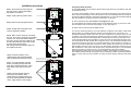
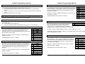
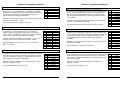
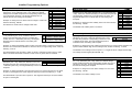
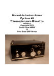
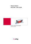
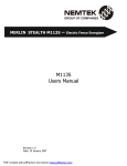
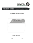
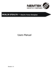
GUARANTEE The Merlin range of energisers, manufactured by IO Tech Manufacturing (Pty) Ltd, are guaranteed for a period of one year from date of sale against defects due to faulty workmanship or materials. IO Tech Manufacturing (Pty) Ltd will, at its discretion, either repair or replace a product that proves to be defective. E-NM28 E-NM25 MERLIN II M-SERIES ELECTRIC FENCE ENERGISER IO Tech Manufacturing (Pty) Ltd guarantees the product, when properly installed and used in line with the specification as determined by IO Tech Manufacturing (Pty) Ltd from time to time, will execute its function of generating a suitable potential. IO Tech Manufacturing (Pty) Ltd does not guarantee that the operation of the product will be uninterrupted or totally error free. Faulty units must be returned to: Nemtek (Pty) Ltd, 64 Vervoer Street, West Industrial Park, Kya Sand, Gauteng, South Africa. Buyer shall pay all shipping and other charges for the return of the product to Nemtek. INSTALLATION MANUAL ELECTRIC FENCE ENERGISER GATE 1 LIMITATION OF GUARANTEE M-SERIES The guarantee does not apply to defects resulting from acts of GOD, modifications made by the buyer or any third party, misuse, neglect, abuse, accident, and mishandling. POWER GATE 2 ON SERVICE ZONE1 ZONE2 GOOD CHECK ALARM EXCLUSIVE REMEDIES The remedies provided herein are IO Tech’s sole liability and buyer’s sole and exclusive remedies for breach of guarantee. IO Tech Manufacturing (Pty) Ltd shall not be liable for any special, incidental, consequential, direct or indirect damages, whether based on contract, tort, or any other legal theory. The foregoing guarantee is in lieu of any and all other guarantees, whether expressed, implied, or statutory, including but not limited to warranties of merchantability and suitability for a particular purpose. NEMTEK GROUP OUTLETS Nemtek Randburg !(+27)(11) 4628283 One Stop Security Shop Germiston !(+27)(11) 8222475 Sparkline Edenvale !(+27)(11) 4521734 Web Site: http//www.nemtek.com E-mail: [email protected] MANUFACTURED IN SOUTH AFRICA 16 M25 M28 Release 1 1 Installation procedures Frequently asked questions. Step1: Open the lid by removing the two cap screws. Unplug the battery terminals if connected. 13 12 Charger Fuse 2 Amp Default Battery Fuse 4 Amp 1 Power Jumper 8 Charger Fuse 2 Amp 9 6 Gate 76 Battery JP1 Fuse 4 Amp 2 On 7 8 Service Jumper 2 JP2 Default Jumper JP1 4 Check 10 5 Alarm 11 3 Good Step2: Unplug the key-switch wires 9 Key Switch Jumper 2 JP2 14 10 Q: The fence alarm goes off and the alarm indicator light does not stop flashing even after I switch the fence off? Auxiliary Fuse 2 Amp A: There is most probably a fault on the fence. Switch the energiser off and disconnect the fence wires at the energiser. Take a short peace of HT wire and bridge the fence-out (Red) and fence-in (Black) terminals. Switch the energiser back on, if the fence indicates GOOD then the energiser is working correctly and the fault is on the fence. Q: After I opened the lid I can’t switch the energiser back on? Step3: Remove the transport screws A: The energiser has a built-in safety switch to avoid electrical shock. If you have to work on the unit while the lid is removed insert jumper 2 (JP2). See page 13 Q: When and for how long will the siren sound? Step4: Unclip with screwdriver and remove energiser chassis A: The siren will be activated by one of the following conditions: Fence Alarm, Gate Alarm, Service Alarm or by holding the Panic button (on the keypad) in for 3 seconds. For a permanent fault like a broken fence wire, the siren will sound for 4 minutes (Siren-on Time) or until the user resets the energiser by switching it off and on again. If the energiser is not reset then it will sound the alarm again after 5 minutes (Siren-off Time). This siren on-off cycle will repeat itself 4 times (Number Of Times The Siren Sounds) after which the siren will not sound unless the fault, broken wire is repaired. For a more intermittent fault like arcing on the fence the siren will sound for 4 minutes followed by a silent period of 5 minutes. The siren is now ready to repeat the 4 minutes on and 5 minutes off cycle as soon as the next fault condition (arcing) occurs. This on-off cycle will repeat 4 times after which the siren will then be silent for 1 hour (Siren Auto Rearm Time). Any faults during the 1 hour will restart this time-out period. At the end of the 1 hour fault free period the siren will rearm automatically and will sound on the next fault condition. The installer can change all the above alarm settings through the keypad. See the following Installer Programming Options: Siren-On Time, Siren-Off Time, Number Of Times The Siren Sounds and Siren Auto Rearm Time. Step5: Drill 4 x 8mm holes for mounting the unit. Four nail in anchors are supplied with the unit. Insert the plastic sleeve of the nail in anchor from the inside of the box and then hammer the screw in with a screw driver and hammer. NB. Always insert the plastic sleeve on the inside of the box. Step6: Insert the battery in the chassis below the energiser board with the positive terminal to the top. Step7: Put the energiser chassis back by inserting the top first and push in the bottom till it locks. Take care that the key-switch wires are clear. 13 12 Charger Fuse 2 Amp Default 8 Charger Fuse 2 Amp Battery Fuse 4 Amp 1 Power Jumper 9 Battery JP1 Fuse 4 Amp 2 On Jumper 2 JP2 Default Jumper JP1 Jumper 2 JP2 6 Gate 76 7 8 Service 3 Good 9 4 Check 10 5 Alarm 11 Key Switch 14 10 Auxiliary Fuse 2 Amp Step8: Connect all the external, key-switch and battery wires. Close the lid by hooking the top of the lid in first and fasten the bottom down. Apply mains to the charger. 2 15 Lo w Vo l t a g e Wi r i n g Di a g r a m Board Layout 12 Charger Fuse 2 Amp 8 Charger Fuse 2 Amp 13 Battery Fuse 6 Default 4 Amp 1 Power Jumper 9 Gate 76 Battery JP1 2 On 7 8 Fuse Service 4 Amp Jumper 2 JP2 Default Jumper 3 Good JP1 4 Check 10 5 Alarm 11 ~ + G A T E1 I NP U T R EMO T E O N/ O F F G A T E2 I NP U T - A U X 12V D C + - Z O NE 1 S T R O B E + + - + - S I R EN O U T P U T Z O NE 2 S T R O B E Ma g n e t i c S w itc h G a te 1 + Ma g n e t i c S w itc h G a te 2 20 W a t t 12V D C S ir e n R e m o te K e y S w itc h + 14 Auxiliary Fuse 2 Amp 2. The Auxiliary fuse powers the Siren, Strobe lights and keypads. MER L I N C H A R G ER S a fe ty Is o la tin g T ra n s fo rm e r + 12V D C S tr o b e L ig h t Z o n e 1/ G a te 1 18V A C 1. Disconnect the mains and battery terminals before replacing any fuses. - 0 . 7 5m m 2 T W I N F L EX # 1 2 C la s s II 3. For normal operation make sure jumper 1 (JP1) is inserted and jumper 2 (JP2) is removed. 3 4 K EY P A D D IP 1 O N O O F F O O N O O F F O A D S W 2 N N F F F F D R ES IT C H 3 O N O O N O O N O O N O + - 12V D C S tr o b e L ig h t Z o n e 2/ G a te 2 D A T S 4 F F F F F F F F K EY P A D # 1 O N 4 1 2 3 4. Lights 12, 13 and 14 are located underneath the fuses. Take care not to damage these lights (LED's) when replacing the fuses. MER L I N F ENC E MO NI T O R + -D A T + D A T K EY P A D # 2 O N 1 2 3 IMPORTANT: Ke e p a l l t h e s e w i r e s a w a y f r o m 14 3 - D A T R EMO T E K EY P A D 9 Key Switch Jumper 2 JP2 10 ~ C H A R G ER 18V A C 4 t h e Hi g h Vo l t a g e w i r e s High Voltage Wiring Diagram Fault Finding General fault conditions: Condition Power Normal On Power Fail Off Battery Low Flash Battery Flat Flash Low Voltage On Service Default 8 Battery Fuse 4 Amp 1 Power Jumper 9 Battery JP1 Fuse 4 Amp 2 On 6 7 8 Service 10 5 Alarm 11 9 Key Switch 14 10 Siren Off Off Off On Off On Comment Normal no fault Check if charger is plugged in Check charger and fuses Check charger and fuses Fence in low voltage mode Service fault see next table Service fault conditions: There are 6 possible conditions that can cause a service alarm. To determine the cause of the service alarm open the lid of the energiser box while the service light is flashing. Make sure that jumper 2 (JP2) is NOT inserted. The following lights will indicate the cause of the service condition: Gate 76 Jumper 2 JP2 Default Jumper JP1 4 Check 3 Good Jumper 2 JP2 Service Off Off Off Flash Off Flash 13 12 Charger Fuse 2 Amp Charger Fuse 2 Amp On On On On Flash Flash Auxiliary Fuse 2 Amp Zone 2 Zone 1 Condition Energiser Faulty Battery Flat 1 Battery Faulty Memory Faulty Keypad Faulty Light (Page14) Alarm (5) Power (1) Battery Fuse (13) Check (4) On (2) 2 Charger Fuse (12) Charger Faulty Aux Fuse Faulty Aux Fuse (14) Comments Send in for repair Check charger and fuses Check battery fuse or replace battery Default to factory settings or send in for repair Check keypad wires and address or send keypad and energiser in for service. See programming function 19. Check charger fuse and charger voltage at energiser. (16VDC or 18VAC) Check auxiliary fuse, keypad, siren and strobe light wires. Earth Electrode 1 To reset a service alarm caused by a battery fault you have to do a manual battery test (6#) or load the factory defaults. If you do a manual battery test it will only reset the service condition after the battery test (5 minutes). 2 A faulty charger will not immediately cause a service alarm but it will cause the battery to run down and that will cause a Battery Flat service alarm. IMPORTANT: Keep all these wires away from the low voltage wires 4 13 Programming Notes 1. To load factory default programming options: Unplug the charger from the mains, disconnect one battery terminal and remove Default Jumper JP1. Reconnect the battery terminal and apply mains to the charger. After the energiser has switched on replace the Default Jumper. 2. After changing the Fence Alarm Voltage setting make sure that a short and open circuit fault can still activate the alarm. 3. The Fence Voltage setting is measured with no load on the energiser. It is possible that the output voltage is lower or higher than indicated in the table if a fence is connected to the energiser. Installation Notes 1. Keep the high and low voltage wiring separate. 2. Use only 0.75mm or thicker cable between the charger and energiser. The charger voltage at the energiser, while it’s pulsing must not drop below 16 VAC or 18 VDC. 3. The wire between the remote key switch and the energiser can be up to a 100m and the switch contact must be closed for the energiser to be on. 4. The auxiliary 12VDC can be used to power a remote receiver but the power consumption must not exceed 0.1 Amps. 5. The siren and strobe light together must not draw more than 1.75Amps. 2 4. If you set the Battery Alarm Voltage to option 0 then the battery will drop out (disconnect itself) before any low voltage indicator will come on. The battery drops out at 9.5 Volts. 6. To connect a radio alarm transmitter or alarm panel to the energiser use an isolation relay between the strobe light output and the panel. Never use the energiser battery to power a radio alarm transmitter or alarm panel. 5. If you use the Gate2 input to switch between high and low fence voltage (Option 13). Then High Voltage = Closed and Low Voltage = Open contact. When in this mode you will not be able to change the fence high / low voltage mode from the keypad. 7. The wire between the magnetic gate switch and the energiser can be up to a 100m but must not run in parallel with the fence wires. The gate switch must be open circuit if the gate is open. 8. The remote keypad cable must not exceed a 100m in total. Avoid running this cable in parallel with any fence (high voltage) wires. 9. Make sure the keypad address dipswitch is set correctly according to the table in the low voltage wiring diagram. You can connect a total of 4 keypads and or fence monitors to one energiser. Remove the power to the keypad before changing the dipswitch settings. 10. Use high voltage insulation wire between the fence and energiser, including the earth wire. Never run these wires in the same conduit or through the same hole as the low voltage wires. 11. Always use ferrules or line clamps to connect two high voltage wires together. Avoid using different types of material for connections like copper on steel. 12. The fence must be earthed properly with at least one earth electrode as close as possible to the energiser. A good rule of thumb is an earth electrode for each 100m of fencing. The distance between the fence earth electrode and other earth systems shall be not less than 10 m. 13. When replacing the lid of the energiser hook the top in first while holding it an angle and then push it closed at the bottom. Fasten the lid down with the two cap screws. 14. If the indicator lights (LED’S), that protrude into the lid are not straight then the lid will not close properly or will damage the indicator lights. Bend the indicator lights straight very gently. 15. Always test the fence alarm for a short and open-circuit after installation at the furthest point on the fence. 12 5 Installer Programming Options Installer Programming Options Enter Programming mode 0# Before any of the installer options can be changed the unit must be in programming mode. To do so enter the 6 digit installer PIN followed by the 0 # keys. The keypad will beep twice if the PIN was correct. The unit is now in programming mode. If no key is pressed for one minute, the system will automatically exit the programming mode. The default Installer PIN is: 0 1 2 3 4 5 Exit Programming mode # When finished it is important to exit the programming mode. While in programming mode you will be unable to access any user functions from the keypad. Installer PIN 00 Siren-On Time 01 Example: To change the Siren-On Time to 3 minutes enter the following. 0 1 4 # The default Siren-On Time is 4 minutes. 0 1 2 3 4 5 6 7 8 9 Siren-Off Time Example: To change the Siren-Off Time to 30 minutes enter the following. 0 2 5 # The default Siren-Off Time is 5 minutes. 6 0 1 2 3 4 5 6 7 8 9 # 10 Sec 30 Sec 1 Min 2 Min 3 Min 4 Min 5 Min 6 Min 7 Min 8 Min 02 The time period for the siren to be silent after the Siren-On Time has elapsed can be changed by pressing the ‘0’ key followed by the ‘2’ key. Select the desired time from the table and press the corresponding number from 0 to 9 followed by the # key. The keypad will beep twice to indicate that the new setting was accepted. 18# The duration of the battery test can be changed by pressing the ‘1’ key followed by the ‘8’ key. Select the desired time period from the table and press the corresponding number from 0 to 9 followed by the # key. The keypad will beep twice to indicate that the new setting was accepted. 0 1 2 3 4 5 6 7 8 9 Example: To change the Battery Test Duration to 30 minutes enter the following. 1 8 5 # The default Battery Test Duration is 5 minutes. 1 Min 2 Min 5 Min 10 Min 15 Min 30 Min 45 Min 60 Min 90 Min 120 Min # The default installer PIN can be changed by pressing the ‘0’ key twice followed by the new PIN and the # key. The new PIN must be 6 digits long. If you can’t remember the PIN, default the unit and use 0 1 2 3 4 5 as the PIN. The time that the siren will be on for can be changed by pressing the ‘0’ key followed by the ‘1’ key. Select the desired time from the table and press the corresponding number from 0 to 9 followed by the # key. The keypad will beep twice to indicate that the new setting was accepted. Battery Test Duration # 0 Min 1 Min 5 Min 10 Min 15 Min 30 Min 1 Hour 3 Hours 6 Hours 12 Hours Keypad Detect Switch 19# The keypad detect switch can be changed by pressing 0 the ‘1’ key followed by the ‘9’ key. Select the desired 1 state from the table and press the corresponding number from 0 or 1 followed by the # key. The keypad will beep twice to indicate that the new setting was accepted. Keypad Detect = OFF Keypad Detect = ON Example: To switch the Keypad Detect Switch on, enter the following. 1 9 1 # The default Keypad Detect Switch is option 0. The energiser will not give a service alarm if there is no keypad(s) connected. Siren Auto Rearm Time 20# The time period for the siren to automatically rearm it self, if no alarm condition is present, can be changed by pressing the ‘2’ key followed by the ‘0’ key. Select the desired time from the table and press the corresponding number from 0 to 9 followed by the # key. The keypad will beep twice to indicate that the new setting was accepted. Example: To change the Siren Auto Rearm Time to 5 minutes enter the following. 2 0 2 # The default Siren Auto Rearm Time is 1 hour. 11 0 1 2 3 4 5 6 7 8 9 0 Min 1 Min 5 Min 10 Min 15 Min 30 Min 1 Hour 3 Hours 6 Hours 12 Hours Installer Programming Options Installer Programming Options Low Power Fence Alarm Voltage 15# The low power fence alarm threshold voltage can be changed by pressing the ‘1’ key followed by the ‘5’ key. Select the desired voltage from the table and press the corresponding number from 0 to 4 followed by the # key. The keypad will beep twice to indicate that the new setting was accepted. 0 1 2 3 4 500 Volts 700 Volts 900 Volts 1200 Volts 1500 Volts Example: To change the Low Power Fence Alarm Voltage to 900 Volts enter the following. 1 5 2 # Number Of Times The Siren Sounds 03# The number of times the siren will sound after an alarm is activated can be changed by pressing the ‘0’ key followed by the ‘3’ key. Select the desired number of times from the table and press the corresponding number from 0 to 9 followed by the # key. The keypad will beep twice to indicate that the new setting was accepted. Example: To change the Number Of Times The Siren Sounds to 10 times enter the following. 0 3 6 # The default Fence Alarm Voltage is 700 Volts. The default Number Of Times The Siren Sounds is 4 times. Battery Alarm Voltage 16# The battery low and alarm threshold voltages can be changed by pressing the ‘1’ key followed by the ‘6’ key. Select the desired voltage from the table and press the corresponding number from 0 to 9 followed by the # key. The keypad will beep twice to indicate that the new setting was accepted. Example: To change the Battery Alarm Voltage to Low = 10.0 Volts and Alarm = 9.0 Volts enter the following. 1 6 2 # The default Battery Alarm Voltage is Low = 11.0 Volts and Alarm = 10.0 Volts Low 9.0 V 9.5 V 10.0 V 10.5 V 11.0 V 11.5 V 12.0 V 12.5 V 13.0 V 13.5 V 0 1 2 3 4 5 6 7 8 9 Battery Test Interval Alarm 8.0 V 8.0 V 9.0 V 10.0 V 10.0 V 10.0 V 11.0 V 11.0 V 11.0 V 11.0 V 17# The frequency at which the unit test the battery can be changed by pressing the ‘1’ key followed by the ‘7’ key. Select the desired time period from the table and press the corresponding number from 0 to 9 followed by the # key. The keypad will beep twice to indicate that the new setting was accepted. Example: To change the Battery Test Interval to every 7 days enter the following. 1 7 4 # The default Battery Test Interval is 1 day. 10 0 1 2 3 4 5 6 7 8 9 12 Hours 1 Day 2 Days 5 Days 7 Days 14 Days 30 Days 60 Days 90 Days Never 0 1 2 3 4 5 6 7 8 9 Gate 1 Delay Time Continuous 1 Time 2 Times 3 Times 4 Times 5 Times 10 Times 20 Times 30 Times 40 Times 04# The time delay for gate 1 to stay open before the alarm is triggered can be changed by pressing the ‘0’ key followed by the ‘4’ key. Select the desired time delay from the table and press the corresponding number from 0 to 9 followed by the # key. The keypad will beep twice to indicate that the new setting was accepted. Example: To change the Gate 1 Delay Time to 60 seconds enter the following. 0 4 2 # The default Gate 1 Delay Time is 4 minutes. 0 1 2 3 4 5 6 7 8 9 Fence Voltage 15 Sec 30 Sec 60 Sec 90 Sec 2 Min 3 Min 4 Min 5 Min 10 Min 15 Min 05# The open circuit fence voltage can be changed by pressing the ‘0’ key followed by the ‘5’ key. Select the desired voltage from the table and press the corresponding number from 0 to 9 followed by the # key. The keypad will beep twice to indicate that the new setting was accepted. Example: To change the Fence Voltage to 6 kV enter the following. 0 5 3 # The default Fence Voltage is 7 kV. 7 0 1 2 3 4 5 6 7 8 9 4.5 kV 5.0 kV 5.5 kV 6.0 kV 6.5 kV 7.0 kV 7.25 kV 7.5 kV 7.75 kV 8.0 kV Installer Programming Options Low Power Fence Voltage 06# The open circuit low power fence voltage can be changed by pressing the ‘0’ key followed by the ‘6’ key. Select the desired voltage from the table and press the corresponding number from 0 to 9 followed by the # key. The keypad will beep twice to indicate that the new setting was accepted. Example: To change the Low Power Fence Voltage to 1000 Volts enter the following. 0 6 4 # The default Low Power Fence Voltage is 800 Volts. Strobe Light Function 0 1 2 3 4 5 6 7 8 9 600 Volts 700 Volts 800 Volts 900 Volts 1000 Volts 1200 Volts 1400 Volts 1600 Volts 1800 Volts 2000 Volts 10# The strobe light output can be changed by pressing the ‘1’ key followed by the ‘0’ key. Select the desired function from the table and press the corresponding number from 0 or 1 followed by the # key. The keypad will beep twice to indicate that the new setting was accepted. 0 0 1 1 Strobe Strobe 1 =Light Zone1 = Alarm / Gate1 Strobe = Zone2 / Gate2 Strobe 2Light = Fence ON Strobe 1 = Fence ON Strobe 2 = High Voltage Example: To change the Strobe Light Function so that the strobe 1 switches on whenever the fence is on and strobe 2 switches on when the fence is in high voltage mode, enter the following. 1 0 1 # The default Strobe Light Function is option 0. Strobe 1 switches on when zone1 or gate1 alarm is activated and Strobe 2 switch on when zone2 or gate2 alarm is activated. Gate 2 Input Function 11# To change the gate 2 input function press the ‘1’ key 0 Gate 2 = Gate 2 input followed by the ‘1’ key. Select the desired function from 1 Gate 2 = Fence Zone 2 the table and press the corresponding number from 0 or 1 followed by the # key. The keypad will beep twice to indicate that the new setting was accepted. Example: To change the Gate 2 Input Function so that you use the fence Zone 2 to detect an open or closed gate and not the magnetic switch input, enter the following. 1 1 1 # The default Gate 2 Input Function is option 0. The magnetic switch input is used to detect an open or closed gate. 8 Gate 2 Delay Time 12# The time delay for gate 2 to stay open before the alarm is triggered can be changed by pressing the ‘1’ key followed by the ‘2’ key. Select the desired time delay from the table and press the corresponding number from 0 to 9 followed by the # key. The keypad will beep twice to indicate that the new setting was accepted. 0 1 2 3 4 5 6 7 8 9 Example: To change the Gate 2 Delay Time to 60 seconds enter the following. 1 2 2 # The default Gate 2 Delay Time is 4 minutes. Fence Voltage Control 15 Sec 30 Sec 60 Sec 90 Sec 2 Min 3 Min 4 Min 5 Min 10 Min 15 Min 13# To change the fence voltage control press the ‘1’ key followed by the ‘3’ key. Select the desired function from the table and press the corresponding number from 0 or 1 followed by the # key. The keypad will beep twice to indicate that the new setting was accepted. 0 1 Gate2 Input Keypad Example: To change the Fence Voltage Control so that you use the Gate2 magnetic switch input to switch between high and low voltage mode, enter the following. 1 3 0 # The default Fence Voltage Control is option 1. To toggle the fence voltage between high to low voltage use the keypad ( 3 #) Fence Alarm Voltage 14# The fence alarm threshold voltage can be changed by pressing the ‘1’ key followed by the ‘4’ key. Select the desired voltage from the table and press the corresponding number from 0 to 9 followed by the # key. The keypad will beep twice to indicate that the new setting was accepted. Example: To change the Fence Alarm Voltage to 2.4 kV enter the following. 1 4 3 # The default Fence Alarm Voltage is 3 kV. 9 0 1 2 3 4 5 6 7 8 9 1.5kV 1.8kV 2.1kV 2.4kV 2.7kV 3.0kV 3.3kV 3.6kV 3.9kV 4.2kV