1
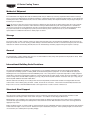
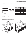
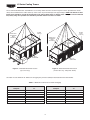
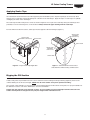
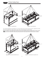
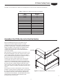
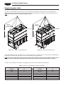
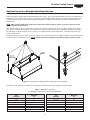
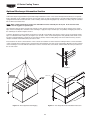
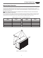
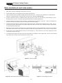
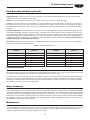
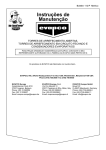
Bulletin 121D
Rigging and
Installation Manual
LS SERIES
FORCED DRAFT EVAPORATIVE COOLING TOWERS
For EVAPCO Authorized Parts and Service, Contact Your Local EVAPCO
Representative or the Local Mr. GoodTower® Service Provider
EVAPCO, Inc. — World Headquarters & Research/Development Center
EVAPCO, Inc. • P.O. Box 1300 • Westminster, MD 21158 USA
PHONE: 410-756-2600 • FAX: 410-756-6450 • E-MAIL: [email protected]
EVAPCO North America
World Headquarters
P.O. Box 1300
Westminster, MD 21158 USA
Phone: 410-756-2600
Fax: 410-756-6450
E-mail: [email protected]
EVAPCO Europe
EVAPCO, Inc.
EVAPCO East
5151 Allendale Lane
Taneytown, MD 21787 USA
Phone: 410-756-2600
Fax: 410-756-6450
E-mail: [email protected]
EVAPCO Midwest
1723 York Road
Greenup, IL 62428 USA
Phone: 217-923-3431
Fax: 217-923-3300
E-mail: [email protected]
EVAPCO West
1900 West Almond Avenue
Madera, CA 93637 USA
Phone: 559-673-2207
Fax: 559-673-2378
E-mail: [email protected]
EVAPCO Iowa
925 Quality Drive
Lake View, IA 51450 USA
Phone: 712-657-3223
Fax: 712-657-3226
EVAPCO Iowa
Sales & Engineering
215 1st Street, NE
P.O. Box 88
Medford, MN 55049 USA
Phone: 507-446-8005
Fax: 507-446-8239
E-mail: [email protected]
Refrigeration Valves &
Systems Corporation
A wholly owned subsidiary of EVAPCO, Inc.
1520 Crosswind Dr.
Bryan, TX 77808 USA
Phone: 979-778-0095
Fax: 979-778-0030
E-mail: [email protected]
McCormack Coil Company, Inc.
A wholly owned subsidiary of EVAPCO, Inc.
P.O. Box 1727
6333 S.W. Lakeview Boulevard
Lake Oswego, OR 97035 USA
Phone: 503-639-2137
Fax: 503-639-1800
E-mail: [email protected]
EvapTech, Inc.
A wholly owned subsidiary of EVAPCO, Inc.
8331 Nieman Road
Lenexa, KS 66214 USA
Phone: 913-322-5165
Fax: 913-322-5166
E-mail: [email protected]
Tower Components, Inc.
A wholly owned subsidiary of EVAPCO, Inc.
5960 US HWY 64E
Ramseur, NC 27316
Phone: 336-824-2102
Fax: 336-824-2190
E-mail: [email protected]
EVAPCO Newton
701 East Jourdan Street
Newton, IL 62448 USA
Phone: 618-783-3433
Fax: 618-783-3499
E-mail: [email protected]
EVAPCO...SPECIALISTS IN HEAT TRANSFER
PRODUCTS AND SERVICES.
EVAPCO Europe, N.V.
European Headquarters
Industrieterrein Oost 4010
3700 Tongeren, Belgium
Phone: (32) 12-395029
Fax: (32) 12-238527
E-mail: [email protected]
EVAPCO Europe, S.r.l.
Via Ciro Menotti 10
I-20017 Passirana di Rho
Milan, Italy
Phone: (39) 02-939-9041
Fax: (39) 02-935-00840
E-mail: [email protected]
EVAPCO Europe, S.r.l.
Via Dosso 2
23020 Piateda Sondrio, Italy
EVAPCO Europe, GmbH
Bovert 22
D-40670 Meerbusch, Germany
Phone: (49) 2159-69560
Fax: (49) 2159-695611
E-mail: [email protected]
Flex coil a/s
A wholly owned subsidiary of EVAPCO, Inc.
Knøsgårdvej 115
DK-9440 Aabybro Denmark
Phone: (45) 9824 4999
Fax: (45) 9824 4990
E-mail: [email protected]
EVAPCO S.A. (Pty.) Ltd.
A licensed manufacturer of EVAPCO, Inc.
18 Quality Road
Isando 1600
Republic of South Africa
Phone: (27) 11-392-6630
Fax: (27) 11-392-6615
E-mail: [email protected]
Evap Egypt Engineering Industries Co.
A licensed manufacturer of EVAPCO, Inc.
5 El Nasr Road
Nasr City, Cairo, Egypt
Phone: 2 02 24022866 /2 02 24044997
Fax: 2 02 24044667/2 02 24044668
E-mail: [email protected] / [email protected]
EVAPCO Asia/Pacific
EVAPCO Asia/Pacific Headquarters
1159 Luoning Rd. Baoshan Industrial Zone
Shanghai, P. R. China, Postal Code: 200949
Phone: (86) 21-6687-7786
Fax: (86) 21-6687-7008
E-mail: [email protected]
EVAPCO (Shanghai) Refrigeration
Equipment Co., Ltd.
1159 Louning Rd., Baoshan Industrial Zone
Shanghai, P.R. China, Postal Code: 200949
Phone: (86) 21-6687-7786
Fax: (86) 21-6687-7008
E-mail: [email protected]
Beijing EVAPCO Refrigeration
Equipment Co., Ltd.
Yan Qi Industrial Development District
Huai Rou County
Beijing, P.R. China, Postal Code: 101407
Phone: (86) 10 6166-7238
Fax: (86) 10 6166-7395
E-mail: [email protected]
EVAPCO Australia (Pty.) Ltd.
34-42 Melbourne Road
P.O. Box 436
Riverstone, N.S.W. Australia 2765
Phone: (61) 2 9627-3322
Fax: (61) 2 9627-1715
E-mail: [email protected]
EvapTech Asia Pacific Sdn. Bhd
A wholly owned subsidiary of EvapTech, Inc.
IOI Business Park, 2/F Unit 20
Persiaran Puchong Jaya Selatan
Bandar Puchong Jaya,
47170 Puchong, Selangor, Malaysia
Phone: (60-3) 8070 7255
Fax: (60-3) 8070 5731
E-mail: [email protected]
Visit EVAPCOʼs Website at:
http://www.evapco.com
LS Series Cooling Towers
Method of Shipment
Forced draft units are shipped either fully assembled (small units) or with the top section(s) separate from the bottom section(s).
These sections have mating flanges and will join together in a waterproof joint when sealed and bolted together as described in the
following instructions. Miscellaneous items, such as sealer, fasteners and any other required materials, are packaged and placed
inside the pan for shipment.
NOTE: All casing sections are factory inspected prior to shipment to verify proper fit for rigging. Please take extra care to handle
and rig unit section per the instructions of this manual to avoid possible distortion and poor casing alignment. It is advisable to
check each section upon receipt and during each lift to ensure that the factory alignment has not been altered. Should the field
inspection indicate the section alignment (“square”) has been altered, please contact the factory or your local EVAPCO
representative for additional instructions to obtain proper section fit.
Storage
Do not place tarps or other coverings over the top of the units if the units are to be stored before installation. Excessive heat can
build up if the units are covered causing possible damage to the PVC eliminators and fill. For extended storage beyond six months
rotate the fan and fan motor shaft(s) monthly. Also, the fan shaft bearings should be purged and re-greased prior to start-up.
General
For extended lifts, or where hazards may exist, it is recommended that safety slings and spreaders be employed for safety. Refer
to the extended lift information in this bulletin.
International Building Code Provisions
The International Building Code (IBC) is a comprehensive set of regulations addressing the structural design and installation
requirements for building systems– including HVAC and industrial refrigeration equipment. As of June 2008, all 50 states plus
Washington D.C. have adopted the International Building Code. The code provisions require that evaporative cooling equipment
and all other components permanently installed on a structure must meet the same seismic design criteria as the building. The LS
Series Cooling Towers are IBC 2006 compliant up to 1.0g (145 psf wind-load) with standard construction and up to 5.12g (145 psf
wind-load) with additional structural modifications.
All items attached to the Evapco LS Cooling Tower must be independently reviewed and isolated to meet applicable wind and
seismic loads. This includes piping, ductwork, conduit, and electrical connections. These items must be flexibly attached to the
Evapco unit so as not to transmit additional loads to the equipment as a result of seismic or wind forces.
Structural Steel Support
Two structural “I” beams running the length of the unit are required for supporting the unit. These beams should be located
underneath the outer flanges of the unit as shown in Figure 1. See Table 1 for Steel Support Dimensions.
Mounting holes, 3/4” in diameter, are located in the bottom flange for bolting to the structural steel. Refer to the recommended
structural steel support drawing and certified print for exact bolt hole location. Bolt the bottom section to the steel support before
rigging the top section.
Beams should be sized in accordance with accepted structural practices. Maximum deflection of the beam under the unit should be
1/360 of the unit length, not to exceed 1/2”. Deflection may be calculated by using 55% of the operating weight as a uniform load
on each beam (see certified print for operating weight).
2
LS Series Cooling Towers
The supporting “I” beams should be level before setting the unit. Do not level the unit by shimming between the bottom flange and
the beams as this will not provide proper longitudinal support.
NOTE: Consult IBC 2006 for required steel support layout and structural design.
Table 1 – Steel Support Dimensions
Unit
Footprint
SOUND
ATTENUATION
5' x 12'
5' x 18'
8P' x 12'
8P' x 18'
8P' x 24'
8P' x 36'
10' x 12'
10' x 18'
10' x 24'
10' x 36'
B2
B1
End Elevation
A
Plan View
Figure 1 – Structural Steel Support
B1
(Unit Only)
5' 5-3/8"
5' 5-3/8"
7' 10"
7' 10"
7' 10"
7' 10"
9' 9-3/4"
9' 9-3/4"
9' 9-3/4"
9' 9-3/4"
B2
Unit with
Intake Attn.)
11' 4-1/2"
11' 4-1/2"
13' 9"
13' 9"
13' 9"
13' 9"
15' 8-3/4"
15' 8-3/4"
15' 8-3/4"
15' 8-3/4"
A
11' 11-1/2"
18' 1/8"
11' 11-3/4"
18' 0"
24' 1"
36' 2-1/4"
11' 11-5/8"
18' 1/4"
24' 3/4"
36' 1-7/8"
Rigging Pan/Fan Section
U-bolts or similar lifting points are located in the pan-fan section for lifting and final positioning purposes as shown below in Figures
2 and 3. Units with lengths up to 18ʼ have 4 total lift points. Units with lengths of 24ʼ and 36ʼ have either 6 or 8 lift points.
NOTE: Use all of the U-bolts or lift points provided for lifting.
LIFTING
EARS
(4 TOTAL)
LIFTING
U-BOLTS
ANGLE WITH
HORIZONTAL
MUST
EXCEED 60°
ANGLE WITH
HORIZONTAL
MUST
EXCEED 60°
LIFTING
U-BOLTS
H
H
Figure 2 – Pan/Fan Section
(up to 18ʼ Long)
Figure 3 – Pan/Fan Section
(24ʼ and 36ʼ Long - 6 lift points shown)
3
LS Series Cooling Towers
The recommended method for extended lifts is to use slings under the unit as shown in Figures 4 and 5. Spreader bars should
always be used between the cables at the top of the section to prevent damage to the upper flanges. NOTE: The U-bolts or other
lifting points should be used for final positioning only and for lifting where no danger exists. If they are used for extended
lifts, safety slings and spreader bars should be provided under the sections as shown.
LIFTING
U-BOLTS
ANGLE WITH
HORIZONTAL
MUST
EXCEED 60°
LIFTING
EARS
(4 TOTAL)
ANGLE WITH
HORIZONTAL
MUST
EXCEED 60°
H
H
3" X 8"
SPREADERS
LIFTING
U-BOLTS
3" X 8"
SPREADERS
Figure 4 – Extended Lift Pan/Fan Section
(up to 18ʼ Long)
Figure 5 – Extended Lift Pan/Fan Section
(24ʼ and 36ʼ Long - 6 lift points shown)
See Table 2 for the minimum “H” dimensions for rigging the pan-fan assembly for both standard and extended lifts.
Unit
Footprint
4' x 6'
4' x 9'
4' x 12'
4' x 18'
5' x 12'
5' x 18'
8P' x 12'
Table 2 – Minimum “H” Dimension for Pan/Fan Rigging
Minimum
“H”
Unit
Footprint
8'
10'
15'
19'
15'
19'
15'
8P' x 18'
8P' x 24'
8P' x 36'
10' x 12'
10' x 18'
10' x 24'
10' x 36'
4
Minimum
“H”
19'
25'
38'
15'
19'
25'
38'
LS Series Cooling Towers
Applying Sealer Tape
Once the bottom section has been set on the supporting steel and bolted in place, wipe the top flanges to remove any dirt or
moisture. Place sealer tape over the mounting hole centerline on the side flanges. Apply two strips of sealer tape, one partially
overlapping the other, on the end flanges.
The sealer tape should overlap on the corners as shown in Figure 6. Do not splice the sealer tape along the end flanges and
preferably not on the side flanges if it can be avoided. Always remove the paper backing from the sealer tape.
For units which have two fill sections, sealer tape must be applied to all internal flanges (Figure 7).
SEALER TAPE
(CENTERED OVER SLOTS)
SEALER TAPE
(CENTERED
OVER SLOTS)
SEALER TAPE
SIDE FLANGE
SIDE
FLANGE
END
FLANGE
SEALER TAPE
(CENTERED
OVER SLOTS)
SIDE FLANGE
Figure 6 – Proper Sealer Tape Application
Figure 7 – Sealer Detail for Center Joint of
Units with Two of More Casing or Fill Sections
Rigging the Fill Section
U-bolts or lift points are provided in the four corners of the fill section for lifting and final positioning (Figure 8). Refer to the
certified drawing for the fill section weight. NOTE: Use all of the U-bolts or lift points provided for lifting.
The end and center eliminator sections should be removed before lifting from the U-bolts or lift points. For proper installation of
the eliminator sections, refer to the “Eliminators” section in this bulletin.
Caution: On units shipped as two separate sections, do not assemble sections and attempt to lift the entire unit. The
U-bolts and lift points are designed to carry only the weight of their individual section.
5
LS Series Cooling Towers
ANGLE
ANG
NGLE WITH
H
O ZONTAL
ORI
HORIZONTAL
MUST EX
CEED 60
MUST
EXCEED
60°°
ANGLE
ANG
LE WITH
H
ORIZONTAL
HORIZONTAL
MUST
MUST EXCEED
EXCEED 60°
60
0°
H
LIFT POINT
H
L
LIFT
POINT
POINT
Figure 8 – Small Fill Section
Figure 9 – Large Fill Section
The recommended method for extended lifts is to use slings under the unit as shown in Figures 10 and 11. Spreader bars should
always be used between the cables at the top of the section to prevent damage to the upper flanges.
NOTE: The U-bolts or other lifting points should be used for final positioning only and for lifting where no danger exists.
If they are used for extended lifts, safety slings and spreader bars should be provided under the sections as shown.
ANGLE
ANG
NGLE WITH
H
O ZONTAL
ORI
HORIZONTAL
MUST EXCEED
EXCEED 60°
60
MUST
ANGLE
ANG
LE WITH
H
ORIZONTAL
HORIZONTAL
MUST
MUST EXCEED
EXCEED 60°
60
0°
H
LIFT POINT
H
L
LIFT
POINT
POINT
3" X 8"
SPREADE
DERS
DE
RS
SPREADERS
3" X 8"
SPREADERS
SPREADERS
Figure 10 – Extended Lift Small Fill Section
6
Figure 11 – Extended Lift Large Fill Section
LS Series Cooling Towers
See Table 3 for the minimum “H” dimensions for rigging the fill section for both standard and extended lifts.
Table 3 – Minimum “H” Dimension for Fill Section Rigging
Unit
Footprint
Minimum
“H”
4' x 6'
4' x 9'
4' x 12'
4' x 18'
5' x 12'
5' x 18'
8P' x 12'
8P' x 18'
8P' x 24'
8P' x 36'
10' x 12'
10' x 18'
10' x 24'
10' x 36'
8'
10'
15'
19'
15'
19'
15'
19'
15'
19'
15'
19'
15'
19'
Assembly of the Fill Section to the Pan-Fan Section
Before assembling the fill section to the pan/fan section,
remove any loose parts shipped in the pan. On small
centrifugal fan units, the fan motor guard is normally shipped in
the basin to avoid damage. It should be attached to the unit
with the self-tapping screws provided. On double fan sided
centrifugal units, the fan motor guards are shipped in a
separate crate with the motors, see the “Motor Installation”
section in this bulletin.
UPPER
UPPE
R SE
SECTION
CTION
ION
Wipe the flanges on the bottom of the fill section. Check to see
that the water distribution connection on the fill section is in the
correct position relative to the pan-fan section (see certified
print). Confirm that sealer tape has been applied to the top of
the pan-fan section as shown in Figures 6 and 7.
ATTACH USING
G
3/8Ø H
ARD
DWAR
WA
W
ARE
AR
HARDWARE
DRIFT
DR
IFT PINS
PINS
Lower the fill section to within several inches of the pan-fan
section making sure the two sections do not touch and the
sealer tape is not disturbed. Place drift pins (see Figure 12) in
at least 3 of the corner mounting holes and gradually lower the
fill section into place using the drift pins to guide the section
down accurately onto the mating flange. On 18 foot and 24 foot
long sections, drift pins should be used midway along the sides
as well.
Place fasteners in all four corner bolt holes. Then continue to
install the rest of the fasteners working from the corners toward
the center, using drift pins to align the holes. A fastener must
be installed in every hole on the side flanges although none
are required on the end flanges. For units with two fill sections,
mount the first as described, and then follow the same
procedure for the second section.
Figure 12 – Mating Fill Section to Pan-Fan Section
M
7
LS Series Cooling Towers
Rigging Complete Units
Units that are shipped with the pan-fan and fill sections assembled can be lifted into final position on the structural steel as a
complete unit. U-bolts or lift points are provided in the fill section below the eliminators for lifting and final positioning (Figure 13).
NOTE: Use all of the U-bolts or lift points provided for lifting.
ANGL
ANGLE
GLE WITH
H
O ZONTAL
ORI
HORIZONTAL
MUST
MUST EXCEED
EXCEED 60°
60°
ANGL
ANGLE
GLE WITH
H
O ZONTAL
ORI
HORIZONTAL
MUST
MUST EXCEED
EXCEED 60°
60°
LIFT POINT
H
LIFT POINT
H
3" X 8"
SPREADERS
RS
SPREADERS
Figure 13 – Complete 4ʼ and 5ʼ Wide Units
Figure 14 – Extended Lift Complete Unit
The recommended method for extended lifts is to use slings under the unit as shown in Figure 14. Spreader bars should always be
used between the cables at the top of the section to prevent damage to the upper flanges.
E
NOTE: The U-bolts or other lifting points should be used for final positioning only and for lifting where no danger exists. If
they are used for extended lifts, safety slings and spreader bars should be provided under the sections as shown.
See Table 4 for the minimum “H” dimensions for rigging the entire unit for both standard and extended lifts.
Unit
Footprint
4' x 6'
4' x 9'
4' x 12'
4' x 18'
5' x 12'
5' x 18'
8P' x 12'
Table 4 – Minimum “H” Dimension for Complete Unit Rigging
Minimum
“H”
8'
10'
15'
19'
15'
19'
15'
Unit
Footprint
8
8P' x 18'
8P' x 24'
8P' x 36'
10' x 12'
10' x 18'
10' x 24'
10' x 36'
Minimum
“H”
19'
15'
19'
15'
19'
15'
19'
LS Series Cooling Towers
Optional Tapered or Straight-Sided Hood Section
Some Units may be supplied with an optional discharge hood section. This section will ship from the factory as a separate item or
mounted on top of either the pan-fan section or fill section to reduce freight charges. Each hood section is equipped with U-bolts
located at the four corners for lifting and final positioning (Figure 15). Always use safety slings for extended lifts or where any
hazard exists.
NOTE: When combined with other sections, the hood must be removed prior to any lift. In all cases the hood section
must be rigged as a separate part.
Once the fill section has been secured to the pan-fan section, wipe the top flanges to remove any dirt or moisture. Place sealer
tape over the mounting hole centerline on the side flanges. Apply two strips of sealer tape, one partially overlapping the other, on
the end flanges as shown in Figures 6 and 7. Remove any shipping blocks or other obstructions. Lower the hood onto the top
flange of the fill section.
Install the fasteners in all four corners as shown in Figure 15. For 18 foot long hoods, two additional fasteners are provided and are
to be fastened in the middle of each side. NOTE: Always lift the hood separately and follow the rigging sequence shown.
LIFTING
U-BOLTS
U-BOLTS
ANGLE
ANGL
E WITH
H
H
ORIZONTAL
A
HORIZONTAL
EXCEED 60°
6 0°
MUST EXCEED
H
Figure 15 – Discharge Hood Rigging and Assembly (Tapered Hood Shown)
See Table 5 for the minimum “H” dimensions for rigging the discharge hood for both standard and extended lifts.
Unit
Footprint
4' x 6'
4' x 9'
4' x 12'
4' x 18'
5' x 12'
5' x 18'
8P' x 12'
Table 5 – Minimum “H” Dimension
for Rigging Discharge Hoods and Discharge Attenuation
Minimum
“H”
Unit
Footprint
8'
10'
15'
19'
15'
19'
15'
8P' x 18'
8P' x 24'
8P' x 36'
10' x 12'
10' x 18'
10' x 24'
10' x 36'
9
Minimum
“H”
19'
15'
19'
15'
19'
15'
19'
LS Series Cooling Towers
Optional Discharge Attenuation Section
Some units may be supplied with an optional discharge attenuation section. This section will ship from the factory as a separate
item or mounted on top of either the pan-fan section or fill section to reduce freight charges. Each discharge attenuation section is
equipped with U-bolts located at the four corners for lifting and final positioning (Figure 16). Always use safety slings for extended
lifts or where any hazard exists.
NOTE: When combined with other sections, the attenuation must be removed prior to any lift. In all cases the hood
section must be rigged as a separate part.
Once the fill section has been secured to the pan-fan section, wipe the top flanges to remove any dirt or moisture. Place sealer
tape over the mounting hole centerline on the side flanges. Apply two strips of sealer tape, one partially overlapping the other, on
the end flanges as shown in Figures 6 and 7.
Lower the attenuation section to within several inches of the fill section making sure the two sections do not touch and the sealer
tape is not disturbed. Place drift pins (see Figure 17) in at least 3 of the corner mounting holes and gradually lower the fill section
into place using the drift pins to guide the section down accurately onto the mating flange. On 18 foot and 24 foot long sections,
drift pins should be used midway along the sides as well.
Place fasteners in all four corner bolt holes. Then continue to install the rest of the fasteners working from the corners toward the
center, using drift pins to align the holes. A fastener must be installed in every hole on the side flanges although none are required
on the end flanges. For units with two attenuation sections, mount the first as described, and then follow the same procedure for
the second section.
Detail A
ANGLE
A
ANGL
E WITH
H
ORIZONTAL
HORIZONTAL
MUST EXCEED
EXCEED 60°
60°
MUST
UPPER
UPPE
R SE
SECTION
CTION
ION
LIFTING
EARS
EARS
ATTACH USING
G
3/8Ø H
ARD
DWAR
WA
W
ARE
AR
HARDWARE
H
DRIFT
DR
IFT PINS
PINS
Figure 16 – Discharge Attenuator Rigging
Figure 17 – Discharge Attenuator Installation Instructions
M
10
LS Series Cooling Towers
Optional Intake Attenuation
Some units may be supplied with an optional intake attenuation section. This section will ship from the factory as a separate item
or mounted on top of either the pan-fan section or fill section to reduce freight charges. Each intake attenuation section is
equipped with U-bolts located at the four corners for lifting and final positioning (Figure 18). Always use safety slings for extended
lifts or where any hazard exists.
NOTE: When combined with other sections, the attenuation must be removed prior to any lift. In all cases the hood
section must be rigged as a separate part.
Move the attenuation section to within several inches of the fan intake section. Place drift pins (see Figure 17) in at least 3 of the
corner mounting holes and gradually move the fill section into place using the drift pins to guide the section accurately onto the
mating flange. On 18 foot and 24 foot long sections, drift pins should be used midway along the sides as well.
Unit
Footprint
Table 6 – Minimum “H” Dimension for Rigging Inlet Attenuation
Unit
Footprint
Minimum
“H”
4' x 6'
4' x 9'
4' x 12'
4' x 18'
5' x 12'
5' x 18'
8P' x 12'
8P' x 18'
8P' x 24'
8P' x 36'
10' x 12'
10' x 18'
10' x 24'
10' x 36'
8'
10'
15'
19'
15'
19'
15'
ANGLE
AN
GLE WITH
H
ORIZONTAL
HORIZONTAL
MUST EXCEED
EXCEED 60°
19'
15'
19'
15'
19'
15'
19'
LIFTING
EA
RS
EARS
H
Figure 18 – Intake Attenuator Rigging
11
Minimum
“H”
LS Series Cooling Towers
Motor Installation (4’ and 5’ wide models)
1.
Study Figure 19 before installing the motor bases on the unit.
3.
Lift the motor/motor base assembly and align holes B to B1 and C to C1. Insert the 1/2 inch diameter pivot bolts with flat
washer D. Install flat washer, nut and jam nut E on the pivot bolt. DO NOT OVERTIGHTEN.
2.
4.
5.
6.
7.
8.
9.
Insert the lifting device into the lifting hole A provided in the motor base.
Insert the J-bolts F into holes G. Install flat washers and cotter pins H. Place nuts, lock washers, and flat washers J on the
threaded portion of J-bolts. Their final location will be behind the motor base installed next.
Insert the J-bolts into the holes K in the motor base. Install flat washers, lock washers, and nuts L. Remove the lifting device
from the motor base and position motor base toward the unit for belt installation.
Install the belts M around the fan sheave and motor sheave (Figure 20). Tighten belts by adjusting nuts on J-bolts. Do not
over tension the belts. When the belts are properly adjusted, the deflection at the center of the belt should be approximately
1/2” with moderate hand pressure.
Measure the distance from the motor base to the J-bolt mounting angles to ensure that both sides of the base are located the
same distance from the unit. This should ensure that the sheaves are properly aligned since they were pre-set at the factory.
As a final check, lay a straight edge from sheave to sheave (Figure 21). There should be 4 point contact. Adjust the position
of the motor sheave if necessary.
To install the motor guard N, line up the holes and fasten with the self-tapping screws P (Figure 20). Check to ensure that the
motor guard does not make contact with the drive sheave or belts.
Figure 19 – Motor Installation
FAN
SHEAVE
Figure 20 – Motor Guard and Powerband Belt Installation
12
MOTOR
SHEAVE
ADJUST POSITION
OF MOTOR SHEAVE
(only if necessary)
Figure 21 – Sheave Alignment Check
LS Series Cooling Towers
Final Assembly and Start-up Details
Shipping Materials - Remove any wood chocks, spare parts, or miscellaneous items that have been placed inside the unit for
shipping purposes. Clean all debris from the basin.
Strainer - Check the strainer in the basin to ensure that it is in its proper location over the pump suction.
Screens - Protective air inlet screens are provided across the front of the fan section of all models. Screens are not provided on
the bottom of the fan section since most of the units are mounted on steel beams, either on the roof or at ground level. If units are
installed in an elevated position, bottom screens are recommended for safety protection and should be provided by the installing
contractor.
Float Valve Adjustment - The float valve is pre-set at the factory, however adjustment should be checked after rigging. The float
valve should be adjusted so that the center of the float is 1” below the center of the overflow connections when the valve is in the
fully closed position. Raise or lower the float by using the wing nuts on the vertical threaded rod. Do not adjust the horizontal rod.
During normal operation, the water level will drop 3” to 4” below the overflow in condensers and coolers; and to approximately 5” to
6” below the overflow in cooling towers. See Table 6 for normal operating level for the LS style units. Note: The float valve has an
available operating pressure between 20 and 50 psi.
Fan Rotation - Bump start and check the fans for proper rotation. Directional arrows are placed on the outside of centrifugal fan
housings or on the inside of axial fan cylinders.
Unit
Footprint
4' x 6'
4' x 9'
4' x 12'
4' x 18'
5' x 12'
5' x 18'
8P' x 12'
Table 6 – Minimum Operating Level
Unit
Footprint
Minimum Level
(inches)
8P' x 18'
8P' x 24'
8P' x 36'
10' x 12'
10' x 18'
10' x 24'
10' x 36'
11''
11''
11''
11''
11''
11''
12''
Minimum Level
(inches)
15''
12''
15''
12''
15''
12''
15''
Freeze Protection
The simplest and most effective way of keeping the recirculated water from freezing is to use a remote sump. With a remote sump,
when the recirculating water pump is shut off all recirculating water drains back to the sump.
If a remote sump is not being used, pan heaters are available. However, the basin heater will not prevent the external piping from
freezing. For installations where water will be left in the basin during freezing conditions, the make-up water supply, and overflow
and drain lines must be heat traced and insulated to protect them from damage. All other connections or accessories at or below
the water level must also be heat traced and insulated.
Water Treatment
Proper water treatment is an essential part of the maintenance required for evaporative cooling equipment. Galvanized equipment
should be passivated prior to equipment startup to avoid the formation of white rust. For more information on passivation and white
rust, please download a copy of EVAPCOʼs Engineering Bulletin 36 at www.evapco.com. The spray water and the fluid inside the
heat transfer coil should both be maintained with a water treatment program to ensure efficient system operation while maximizing
the equipmentʼs service life. For more information on recommended water chemistry for EVAPCO equipment, see the Operation
and Maintenance Instructions for this equipment.
Maintenance
Once the installation is complete and the unit is turned on, it is important that it be properly maintained. Maintenance is not difficult
or time-consuming but must be done regularly to assure full performance of the unit. Refer to the operation and maintenance
instructions supplied with the unit for proper maintenance procedures.
13
LS Series Cooling Towers
Accessory Location Checklist
Accessories can ship in a variety of locations depending on the type of accessory, the size of the unit and the accessories
purchased with the unit. See Table 10 for a guide to accessory location.
Unit Accessories
Table 10 – Unit Accessory Shipping Location
Aluminum Ladder
Discharge Attenuation
Discharge Hood with Dampers
Electric Basin Heater
Electric Basin Heater Control Panel
Electric Basin Heater Low Water Cutout
Electric Basin Heater Thermostat
Electronic Water Level Control Probes
Electronic Water Level Control
External Service Platform with Ladder
Fan Screens (If not mounted)
Fan Screen Supports (If not mounted)
Flume Plate
Hot Water or Steam Coil
Inlet Attenuation
Shipping Location
Shipping Location is Unit and Accessory Dependent
- If Space is Available: Strapped Inside Unit Basin
- If No Space is Available: Shipped Separately on Truck Bed
Shipping Location is Unit Dependent
- 4' Wide Units: Shipped Separately on Truck Bed
- 8' Wide Units and Larger: Mounted Loosely Bolted on Basin
Shipping Location is Unit Dependent
- 4' Wide Units: Shipped Separately on Truck Bed
- 8' Wide Units and Larger: Mounted Loosely Bolted on Basin
Shipping Location is Unit Dependent
- End Mounted Heater: Installed in Unit Basin
- Side Mounted Heater: Strapped Inside Unit Basin
Shipping Location is Dependent on Control Panel Size
- If Space is Available: Mounted on Unit Basin
- If No Space is Available: Boxed, Wrapped and Wire Tied Inside Unit Basin
Shipped in Rigging Box Strapped Inside Unit Basin
Shipping Location is Unit Dependent
- End Mounted Thermostat: Mounted on Unit Basin
- Side Mounted Thermostat: Shipped in Rigging Box
Mounted in PVC standpipe
PVC Standpipe Strapped Inside Unit Basin
Shipping Location is Unit and Accessory Dependent
- If Space is Available: Strapped Inside Unit Basin
- If No Space is Available: Crated and Shipped Separately on Truck Bed
Shipping Location is Unit and Accessory Dependent
- If Space is Available: Strapped Inside Unit Basin
- If No Space is Available: Crated and Shipped Separately on Truck Bed
- If Space is Available: Strapped Inside Unit Basin
- If No Space is Available: Crated and Shipped Separately on Truck Bed
Mounted to Flume Box
Installed in Unit Basin
Shipping Location is Unit Dependent
14
15
1500/0211/YGS
EVAPCO, Inc. • P.O. Box 1300 • Westminster, MD 21158 USA
PHONE: 410-756-2600 • FAX: 410-756-6450 • E-MAIL: [email protected]
©2011 EVAPCO, Inc.
Printed on recycled paper
using soy-based ink