1
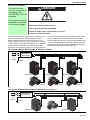
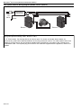
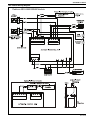
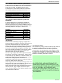
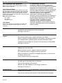
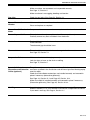
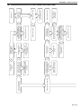
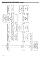
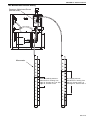
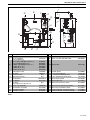
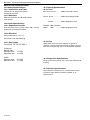
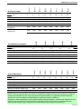
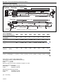
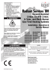
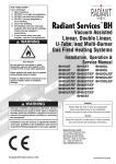
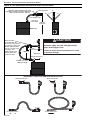
BLACKHEAT® INSTALLATION OPERATION AND SERVICE MANUAL
Figure 34: Gas Connection with Stainless Steel Flex Connector
CORRECT POSITIONS
Stainless Steel Flexible Connector
supplied by Roberts-Gordon 1000 mm Long
Minimum Bend Radius 140 mm
Shut-Off Valve
0°
45°
45°
Gas Supply Pipe
Flex Line
Connector
545 mm
minimum
Burner
Correct position with flex connector not supplied by Roberts-Gordon.
Shut-Off Valve
(included with gas
hose) must be parallel
to burner gas inlet. The
80 mm displacement
shown is for the cold
condition. This
displacement may
reduce when the
system is fired.
CAUTION
Product Damage Hazard
80 mm
max. displacement
300 mm
Hold gas nipple securely with pipe wrench
when attaching gas hose.
Failure to follow these instructions can result
in product damage.
Side View
Heater Movement
Flexible Gas Hose
1000 mm length
INCORRECT POSITIONS (WRONG INSTALLATION)
Heater Movement
Heater Movement
54 of 74
Heater Movement
Heater Movement
SECTION 13: WIRING
SECTION 13: WIRING
DANGER
All electrical wiring
must be carried out an
accordance with
AS/NZS 3000-2007 as
amended.
Basic appliance wiring
installation is detailed
in the following page.
Electrical Shock Hazard
Disconnect electric before service.
Heater must be properly grounded.
Failure to follow these instructions can result
in death or electrical shock.
Connect to the electrical supply using a 3 pin plug via a
locally mounted double pole fused switch having a
minimum disconnection of 3 mm on each pole. This
switch should be fused to 3 amps. The burner is fused at
2 amps. There are no control connections in the standard
burner. Control is affected by interruption of the main
power inlet. See Page 55, Section 13.1 through Page 56,
Section 13.4 for the external wiring details for the singleburner, double linear and multiburner heater systems.
All wiring must comply with current wiring regulations and
any local regulations which may apply. Always switch off
the supply to the burner and disconnect by removing the
plug before removing the burner side panel.
13.1 Typical External Wiring Diagram (Linear or U-Tube)
230 V
1Ø
50 Hz
L
Controller or
N Thermostat
L
N
Earth
Earth
Burner 1
Burner 2
Burner 3
Fan 1
Fan 2
Fan 3
13.2 Typical External Wiring Diagram (Double Linear Option 1)
230 V
1Ø
50 Hz
L
N
Controller or
Thermostat
L
N
Earth
Earth
Burner 1
Fan
Burner 2
55 of 75
BLACKHEAT® INSTALLATION OPERATION AND SERVICE MANUAL
13.3 Typical External Wiring Diagram (Double Linear Option 2)
L
N
230 V
1Ø
50 Hz
Controller or
Thermostat
L
N
Earth
Earth
Fan
Burner 1
Burner 2
13.4
Typical
External Wiring
Diagram
(Multiburner)
Wiring
Note [Interconnecting
Cable
- Burner
to Fan]:For 'U' Tube heaters, fan will plug directly into burner pack. For Linear and double linear heaters, an
interconnecting cable will be required between the fan plug and burner socket. This cable shall be three core
suitable for current load of 10A and shall be installed clear of appliance in accordance with 'Clearances to
Combustibles' data. The required plug and socket for this cable are supplied with the appliance; cable is not
included.
56 of 74
SECTION 13: WIRING
13.5 Internal Wiring Diagram
Pektron ASS-0692G206B Module
57 of 75
BLACKHEAT® INSTALLATION OPERATION AND SERVICE MANUAL
SECTION 14: OPERATION
WARNING
DANGER
Electrical Shock Hazard
Explosion Hazard
Burn Hazard
Turn off gas supply to
heater before service.
Disconnect electric
before service.
Allow heater to cool
before service.
Cut/Pinch Hazard
Wear protective gear
during installation,
operation and service.
Tubing may still be hot
Edges are sharp.
after operation.
More than one
disconnect switch may
be required to
disconnect electric from
heater.
Heater must be
connected to a properly
grounded electrical
source.
Failure to follow these instructions can result in death, electric shock, injury or property damage.
Figure 35: Sequence of Operation Chart
T0
KEY TO
SYMBOLS
T1
T2
T3
T4
T5
T6
T7
T8
Thermostat
Fan
P
P
Pressure
Switch
Fan Neon
Neon
Ignition
Gas
Valve
Flame
Sensing
Burner Neon
Lockout Alarm
Signal (optional)
Tp
Tp
Ts
10 sec
10 sec
10 sec
40 sec max.
11 sec typical
Interruption of main
flame sensing
Burner Lockout
signal received after
3 ignition trial
failures
NOTE: If the heater operates for more than 24 hours continuously, the ignition module will automatically recycle the
burner to ensure that all safety functions are still in working condition.
14.1 Heater Lockout Indication (Optional)
In case of flame loss during operation of the heater, the
burner control unit goes to lockout mode after three
ignition trials. At this stage a signal or closed relay will
enable the ROBERTS GORDON® controller, BMS
58 of 74
system, etc. to indicate precisely which heater has failed.
This can be done by two options.
SECTION 14: OPERATION
14.1.1 Heater Lockout Indicator by Connector
A 230 V signal is provided which enables the ROBERTS
GORDON® controller, BMS system, etc. to indicate the
heater that has failed. An additional wire has to be
installed from the heater lockout indicator connector to
the monitoring computer. See Page 57, Section 13.5.
Description
Connector male - Lockout Indicator
Connector female - Lockout Indicator
Wire Blue 12"
Wire Brown 12"
Part Number
91324000
91324001
91300011
91300012
14.1.2 Heater Lockout Indicator by Volt Free
Connector
A volt free contact relay is closed which enables the
ROBERTS GORDON® controller, BMS system, etc. to
indicate the heater that has failed. An additional wire has
to be installed from the heater volt free connector to the
monitoring computer. See Page 57, Section 13.5.
3. With the gas supply off at each of the burners and
the electrical supply isolated, open the control
chamber secured by two self tapping screws.
4. Ensure that all time clocks and thermostats are set
to call for heat.
5. Switch on the electrical supply at the main isolator.
This will start the exhaust fan.
6. Balancing Cold Vacuum
Check each burner vacuum by connecting an
inclined pressure gauge to the tee on the pressure
switch inlet side in the burner. Adjust the damper so
that the vacuum is 1.9 mbar. Repeat for each burner.
7. Starting at the end burner (furthest from the exhaust
fan), with the inclined pressure gauge connected as
described above. Turn on the gas supply and connect appliance electrical plug, reset the pressure
switch by removing vacuum from the inlet side of the
Description
Part Number
pressure switch waiting several seconds and reconConnector male - Volt Free
91324000
necting. The start up sequence described on Page
Connector female - Volt Free
91324001
58, Section 14 should take place. If not, refer to
Wire Blue 7"
91300004
Wire Brown 7"
91300005
detailed fault finding sequence. When flame is
Wire Yellow 12"
91300003
established, check the gas pressure reading and
Screw #8 x 3/8 Hex Wshr PHH Type 23
94961406
adjust if necessary. See data label.
Base relay P2RF05E
C1050B
Check the gas pressure at the outlet of the gas
Relay G2R1-SN IMO 220 V 10 A
C1049B
valve. See Page 74, Section 18.9.1 or See Page 75,
Section 18.9.2 for pressure settings or refer to the
14.2 Testing
data plate.
Switch off the electrical supply (shutting down the
Establish that a satisfactory purged gas supply and an
heater), remove pressure gauge - refit pressure testelectrical supply is available to the heater. Ensure that all
point screw, ensuring a tight gas seal. Replace govtime clocks and thermostats are set to call for heat.
ernorInstructions.
cover cap.
With the gas supply cut off at the appliance isolating cock 14.5 User
After satisfactory
ensure
the client
Repeat this testing,
procedure
for each
burnerisinfully
the aware
sys- of
and the electrical supply isolated by switching off at the
the
operation
of
the
heaters
and
system.
Bring
this
tem.
local switch and removing the appliance inlet plug, open
to the
of the user
/ or purchaser;
Close
theattention
control chamber
andand
secure
with two
the control chamber secured by the two screws. Loosen manual
instruct
them
in
the
safe
operation
of
the
heater/s. Advise
sheet metal screws.
the sealing screw from the pressure test point and
the user that if the system is unflued, any reduction in the
remove the cover cap from the governor.
ventilation
of the Hot
building
may require a flue to be fitted, or
8. Balancing
Vacuum
Turn on the gas supply and connect appliance electrical additional ventilation grilles will be required.
Reconnect all the burners on the system and allow
plug. Ensure that the timer or thermostat, if fitted, are set
them to reach full operating temperature (approxito call for full gas rate. Switch on at the local switch. The
mately 20 minutes). Return to each burner and
sequence as described should take place. If not, refer to
recheck the hot vacuum at the tee on the inlet to the
detailed fault finding sequence. When flame is
pressure switch. Readjust the damper so that the
established, check the gas pressure reading and adjust if
hot vacuum of 1.5 mbar (2.0 mbar for BH40EF) is
necessary. Refer to burner data label.
achieved and lock the damper in position.
Check the gas pressure at the outlet of the gas valve. See
Page 74, Section 18.9.1 or See Page 75, Section 18.9.2 ALL
AND MAINTENANCE OF
14.4 SERVICING
System Checks
for pressure settings or refer to the data plate.
Switch onAPPLIANCES,
again at the local switch
to ensure smooth
THESE
AS DETAILED
IN THE
ignition. Carry outSECTIONS,
the following system
checks:
Switch off the electrical supply (shutting down the heater), FOLLOWING
SHALL
BE CARRIED
When running, turn off the gas supply at the appliance.
remove pressure gauge - tighten pressure test point
OUT
BY SUITABLY
AUTHORISED
ANDby three
The
heater
will immediately
shut down followed
screw, ensuring a tight gas seal. Replace governor cover
ignition attempts
followed by lockout.
QUALIFIED
PERSONNEL
AND
SHALL
BE IN
cap. Close burner side cover.
Linear
and
Double
Linear
only:
ACCORDANCE WITH THE INSTRUCTIONS IN
When running,
disconnect the fan plug from the burner.
THIS
MANUAL.
14.3 Commissioning (Multiburner)
The unit should shut down within three seconds, proving
1. Establish that a satisfactory purged gas supply and operation of the pressure switch.
an electrical supply is available to the heater.
14.5 User Instructions
2. ENSURE that all the dampers are in the fully open
position.
After satisfactory testing, ensure that the client is fully
aware of the operation of the system. Bring this manual to
59 of 75
SECTION 15: SERVICING INSTRUCTIONS
SECTION 15: SERVICING INSTRUCTIONS
WARNING
DANGER
Electrical Shock Hazard
Disconnect electric
before service.
Explosion Hazard
Turn off gas supply to
heater before service.
More than one
disconnect switch may
be required to
disconnect electric from
heater.
Burn Hazard
Allow heater to cool
before service.
Cut/Pinch Hazard
Wear protective gear
during installation,
operation and service.
Tubing may still be hot
Edges are sharp.
after operation.
Heater must be
connected to a properly
grounded electrical
source.
Failure to follow these instructions can result in death, electric shock, injury or property damage.
IMPORTANT: Never use the heater as a support for
ladders or other access equipment. Always test for gas
soundness with a suitable detection fluid after completing
any servicing or exchange of gas carrying component.
On completion of any service/fault finding tasks which
require the breaking and remaking of electrical
connections, the checks:- A:Earth Continuity, B:Polarity
and C:Resistance to Earth must then be repeated.
15.1 Annual Procedure
Carry out the following procedure annually. The preferred
time would be immediately before the winter heating
period. If very dirty conditions arise, it may be necessary
to carry out this procedure more often. If the unit takes in
air through an air duct or filter assembly, more frequent
service may be necessary.
order. Carry out the Testing Procedure. See Page 59,
Section 14.2.
15.2 Component Removal
First, isolate the heater from the gas and electrical
supplies. Entry to the burner assembly is gained by
removing the door screws and opening the hinged side
cover. Entry to the combustion chamber is gained by
removing the combustion chamber cover.
15.2.1 Electrode
Figure 36: Burner Cup Position
15.1.1 Burner and Fan Removal
Isolate the heater from the gas and electrical supplies.
Remove the fan plug from the burner. Unscrew the
securing screws on the burner flange. The burner can
now be removed. Take care not to disturb the gasket on
the flanged burner tube. Unscrew the securing screw on
the fan flange spigot. The fan can now be removed.
15.1.2 Burner and Fan Removal Maintenance
Remove the fan and burner independently to floor level
and clean both items internally using a soft brush and
compressed air, if available. Take care not to damage the
internal parts of the burner. Check fan impeller for
cleanliness and free rotation.
The electrodes are an integral part of the burner. To
check spark gap, remove the securing screws on the
electrode and withdraw it ensuring the gasket is not
damaged. Spark gap on electrode should be
approximately 3 mm.
15.1.3 Tube and Reflector Maintenance
With burner and fan removed, clean the outer surfaces of
the tubes using a brush and wipe the inner surface of the
reflector with a soft damp cloth - use a household
detergent if necessary. Never use abrasive cleaners on
the reflectors. Reassemble the burner and fan in reverse
[Note page 60 has been deleted].
15.2.2 Burner Head/Injector Jet
When the cover is removed completely, the burner
assembly is exposed. Unscrew the burner cup. Remove
brass injector jet (orifice). Replace in reverse sequence.
15.2.3 Solenoid Valve/Governor
Remove burner head. Remove screws securing the
solenoid/governor body bracket. Withdraw the four wires
between the solenoids. The solenoid/governor and
fittings can now be withdrawn from the compartment. The
solenoid(s) can be removed from the body by unscrewing
central screw. Replace in reverse sequence. Note: Earth
is green/yellow.
61 of 75
BLACKHEAT® INSTALLATION OPERATION AND SERVICE MANUAL
15.2.4 Automatic Flame Control Unit
Remove black ignition lead. Withdraw the connectors.
Remove two screws from the cover. Replace if faulty.
Refit in reverse sequence.
15.2.5 Pressure Switch
Disconnect the two silicone tubes. Remove wires from
the three blades. Remove two screws which secure the
pressure switch to the burner. Remove pressure switch.
Replace pressure switch, if faulty, and refit in reverse
sequence ensuring that the rubber tubes are reconnected
to the switch correctly.
Note: Wires fitted as follows:
NO - Yellow
NC - White
Common - Black
15.2.6 Neons
Remove the two push on connectors and remove the
neons by pushing downwards. Replace in reverse
sequence.
The Vicinity of the Heater
15.3 Maintenance Checklist
Installation Code and Annual Inspections:
All installation and service of ROBERTS GORDON®
equipment must be performed by a contractor
qualified in the installation and service of equipment
sold and supplied by Roberts-Gordon and conform
to all requirements set forth in the ROBERTS
GORDON® manuals and all applicable
governmental authorities pertaining to the
installation, service and operation of the equipment.
To help facilitate optimum performance and safety,
Roberts-Gordon recommends that a qualified
contractor conduct, at a minimum, annual
inspections of your ROBERTS GORDON®
equipment and perform service where necessary,
using only replacement parts sold and supplied by
Roberts-Gordon.
Do not store or use flammable objects, liquids or vapours near the heater.
Immediately remove these items if they are present.
See Page 5, Section 3.
Vehicles and Other
Objects
Maintain the clearances to combustibles.
Do not hang anything from, or place anything on, the heater.
Make sure nothing is lodged underneath the reflector, in between the tubes
or in the decorative or protective grilles (included with select models).
Immediately remove objects in violation of the clearances to combustibles.
See Page 5, Section 3.
Reflector
Support reflector with hanger and support strap.
Reflector must not touch tube.
Make sure there is no dirt, sagging, cracking or distortion.
Do not operate if there is sagging, cracking or distortion.
Make sure reflectors are correctly overlapped. See Page 23, Section 6.6.1.
or Page 34, Section 7.8.1.
Clean outside surface with a damp cloth.
Vent Pipe
Venting must be intact. Using a flashlight, look for obstructions, cracks on
the pipe, gaps in the sealed areas or corrosion.
The area must be free of dirt and dust.
Remove any carbon deposits or scale using a wire brush.
See Page 50, Section 11.
Outside Air Inlet
Inlet must be intact. Look for obstructions, cracks on the pipe, gaps in the
sealed areas or corrosion.
The area must be free of dirt and dust. Clean and reinstall as required.
62 of 74
SECTION 15: SERVICING INSTRUCTIONS
Tubes
Make sure there are no cracks.
Make sure tubes are connected and suspended securely.
See Page 11, Section 5.
Make sure there is no sagging, bending or distortion.
Gas Line
Check for gas leaks. See Page 53, Section 12.
Burner Observation
Window
Make sure it is clean and free of cracks or holes.
Blower Scroll, Wheel and
Motor
Compressed air or a vacuum cleaner may be used to clean dust and dirt.
Burner Cup and Orifice
Clear of obstructions (even spider webs will cause problems).
Carefully remove any dust and debris from the burner.
Electrode
Replace if there are cracked ceramics, excessive carbon residue, or erosion
of the electrode.
Clean and replace as required.
The electrode gap should be 3 mm.
Thermostat
There should be no exposed wire or damage to the thermostat.
See Page 55, Section 13.
Suspension Points
Make sure the heater is hanging securely.
Look for signs of wear on the chain or ceiling.
See Page 11, Section 5.
Sports Hall Guard,
The grille must be securely attached. If the grille is loose or off, contact a
Decorative and Protective contractor qualified in the installation and service of gas-fired heating equipGrilles (optional)
ment for repair.
Check that side reflector extensions are installed correctly and secured in
place if necessary (decorative grille only).
See Page 42, Section 10.1 and Page 45, Section 10.4.
Make sure shield is installed correctly and secured in place if necessary.
(Decorative grille only.) See Page 44, Section 10.3.2.
Wall Tag
If a wall tag is present, make sure it is legible and accurate. Please contact
Roberts-Gordon LLC or your ROBERTS GORDON® independent distributor
if you need a wall tag. See Page 4, Section 2.1.
63 of 75
BLACKHEAT® INSTALLATION OPERATION AND SERVICE MANUAL
SECTION 16: TROUBLESHOOTING
DANGER
Electrical Shock Hazard
Disconnect electric before service.
Heater must be properly grounded.
Failure to follow these instructions can result
in death or electrical shock.
WARNING
Fire Hazard
Keep all flammable
objects, liquids and
vapors the minimum
required clearances to
combustibles away
from heater.
Explosion Hazard
Turn off gas supply to
heater before service.
Burn Hazard
Allow heater to cool
before service.
Cut/Pinch Hazard
Wear protective gear
during installation,
operation and service.
Tubing may still be hot
Edges are sharp.
after operation.
Some objects will catch
fire or explode when
placed close to heater.
Failure to follow these instructions can result in death, injury or property damage.
64 of 74
No
Is there spark at the igniter? No
Yes
Turn up thermostat.
Does the fan turn on?
Replace automatic
control unit.
Carefully reset gap
to 3 mm.
Replace electrode and
ignition wire as needed.
Is the igniter gap
set at 3 mm?
Check relay wiring
(if applicable) and wiring
to the burner.
No
Is there power (230V)
at the burner?
Yes
Is there power out
from pin 10 on
ignition module?
No
No
No
No
Yes
Unplug burner and check
electrode and ignition wire.
Are they damaged?
Check thermostat wiring
and replace thermostat if
necessary.
Place a jumper across
the thermostat terminals.
Does the fan turn on?
Yes
Replace ignition
module.
No
Yes
Yes
Yes
Replace pressure switch.
Remove Black and Yellow
leads from the pressure switch;
place a jumper between leads.
Is there a spark?
Yes
Yes
Are the hoses to the pressure No
switch secure and leak free?
No
Is the flue pipe or
the inlet of the
burner obstructed?
Remove obstruction.
Replace pressure switch.
Remove Black & White
leads from the pressure switch; No
place jumper between leads.
Does the fan turn on?
Yes
Yes
Repair, replace or
tighten hoses
as necessary.
Remove obstruction.
Fan bearings may have
failed. Replace fan.
No
Is the fan obstructed?
No
Unplug burner.
Does the fan
turn freely?
Yes
Replace Fan.
SECTION 16: TROUBLESHOOTING
16.1 Troubleshooting Flow Chart (Linear, Double Linear and U-Tube)
65 of 75
66 of 74
No
No
Roberts-Gordon at
Tel: +44 (0)121 506 7700 or
Fax: +44 (0)121 506 7701 or
online at www.rg-inc.com
TROUBLESHOOT ENDS.
If problems persist, contact
Yes
Does the burner turn off
No
when the call for heat ends?
Yes
Does the burner
stay on?
Yes
Does the burner light?
Yes
Check the thermostat and
check the continuity of the
ground wire.
Reverse polarity.
Reestablish continuity.
Are the Live and Neutral
reversed?
Replace automatic
control unit.
Yes
Are the wires connecting the
automatic control unit OK?
No
Measure voltage on valve
terminals. Is there 230 V
during ignition time?
Purge Lines.
Yes
Yes
Yes
No
No
Is the continuity of the
earth wire established?
Check gas line stop cock.
Check gas supply at meter.
Contact gas company.
Is there sufficient inlet gas
pressure (See Specification
Section) during ignition?
No
Yes
Were the gas lines
purged of air correctly?
No
No
Yes
Re-establish connections.
No
Is the wiring at the
module properly
connected?
Replace/Correct wires.
Is there gas outlet pressure
available during the
ignition period?
Yes
Is the gas outlet pressure
in accordance with
specification section
of this manual?
Yes
Check for the proper jet
and air plate inside the
burner.
Yes
No
No
Replace/Correct
Wires.
No
Is the insulation on the
electrode/sensor leads
OK?
Yes
Ignition module may have
failed. Replace module.
Replace solenoid
coil.
Adjust the governor
pressure.
BLACKHEAT® INSTALLATION OPERATION AND SERVICE MANUAL
Troubleshooting Flow Chart (Linear, Double Linear and U-Tube)
SECTION 16: TROUBLESHOOTING
16.3 Manifold Gas Pressure Setting
Governor Adjustment Screw
(behind cover)
Manometer
6
6
5
5
4
4
3
3
2
2
1
0
1
Governor (orifice) pressure
while burner is running. See
Page 74, Section 18.9.1 or See
Page 75, Section 18.9.2
1
0
1
2
2
3
3
4
4
5
5
6
6
Gas Supply pressure
while burner is running. See
Page 74, Section 18.9.1 or
See Page 75, Section 18.9.2
69 of 75
BLACKHEAT® INSTALLATION OPERATION AND SERVICE MANUAL
SECTION 17: REPLACEMENT PARTS
WARNING
DANGER
Electrical Shock Hazard
Explosion Hazard
Fire Hazard
Carbon Monoxide Hazard
Use only genuine ROBERTS GORDON® replacement parts per this installation, operation and
service manual.
Failure to follow these instructions can result in death, electric shock, injury or property damage.
70 of 74
SECTION 17: REPLACEMENT PARTS
A
E
D
F
C
G
H
Q
N
I
L
O
M
K
Item Description
A Automatic Control Unit
C Flex Line Adapter
Pressure Switch for
BH25 - BH55, BH50EF, (0.23" w.c.)
BH15 and BH20 (0.32" w.c.)
D BH30EF and BH35EF (0.41" w.c.)
BH45EF (0.47" w.c.)
BH40EF (0.79" w.c.)
BH25EF (0.59" w.c.)
E Amber Neon Lamp
F Gas Valve
G Governor Screw
H Outlet Pressure Tap
I Flex Manifold
J Star Washer
Jet Orifice
K
(See Page 74, Section 18.9.1)
L Burner Cup Assembly
M Mica Window Assembly
N Electrode Assembly
N/S Electrode Gasket
J
Part Number
90438702
91220700
90439801
90439802
90439803
90439804
90439808
90439809
91320602
90033101
N/A
N/A
03090702T
96212100
N/A
03020100
02552303
90427403
02558501
Item Description
O Dust Arrest Baffle Plate
Q Mains in socket with EMC Filter
Part Number
07230000
90438902
N/S Ignition Wire
90427704
N/S Outside Air Kit
N/S Flue Collar 100 mm
N/S Outside Air Mounting Plate
N/S #8 x 3/8 Washer Head Screw
N/S Burner Tube Gasket
N/S Wire Purple 12.5"
07260000
91911700
07261000
94118106
02568200
07250007
N/S Wire Harness BH Gas Valve
07250006
N/S
N/S
N/S
N/S
07250005
07250004
91324000
91324001
Wire Harness BH Pressure Switch
Wire Harness BH Main Power
Lockout Indicator Connector (male)
Lockout Indicator Connector (female)
Notes:
71 of 75
BLACKHEAT® INSTALLATION OPERATION AND SERVICE MANUAL
SECTION 18: SPECIFICATIONS
18.1 Material Specifications
18.1.1 Combustion and Tubes
18.3 Venting Specifications
18.3.1 Fans
100 mm dia. 16 gauge heat treated
aluminised mild steel.
BH-15, 20, 25, 30............. Model: Torin DSF 133-42
18.1.2 Reflectors
BH-25 EF, 30 EF, 35 EF,
BH-35, 40, 45 .................. Model: Torin DSA 524-202
NS3 H14 aluminium or 1.4016 2R stainless
steel (option).
18.2 Heater Specifications
18.2.1 Sequence Controller
Fully automatic, three try, direct spark, 100% shut off
ignition flame rectification module.
BH-40 EF, 45 EF,
50 EF, BH-50 .................. Model: Magnetek JF1G
BH30DL, 40DL, BH50DL/EF,
60DL/EF, 70DL/EF........... Model: Magnetek JF1G
Multiburner
.................. Model: Airflow 83 BTLW
.................. Model: Airflow 90 BTLW
18.2.2 Electrical
Rating: 230V, 50 Hz, 1 Ø, 1 A
Connection: 3 pin moulded plug
18.2.3 Gas Supply
Connection:Rc
Rc1/2
Connection:
1/2 (1/2"
[1/2"BSP
BSPint)
]
Natural G20:
Consult the manufacturer for availability of alternate fans.
18.3.2 Flue
When fitted, the flue must be 100 mm, or greater in
diameter, and must conform to National Codes. The flue
must be self supporting. Inlet must be 100 mm diameter.
Pressures:Minimum - Inlet 15 mbar (6 in wg)
Natural
Gas:-- Inlet 50 mbar (20 in wg)
Maximum
Minimum Inlet 1.13 kPa
Maximum Inlet
5.0 kPa
Multiburner - Flue must be 150 mm diameter and will be
sized to suit arrangement and will connect to the fan. Flue
material must conform to National Codes. The flue must
be self supporting.
Minimum - Inlet 17.5 mbar (7 in wg)
ULPG
Minimum
Inlet- Inlet
2.75
kPa (20 in wg)
Maximum
50 mbar
Maximum Inlet
5.0 kPa
18.4 Suspension Specifications
Natural G25:
Hang heater with materials with a minimum working load
of 33 kg.
LP Gas (Propane or Butane):
Minimum - Inlet 32.5 mbar (13 in wg)
Maximum - Inlet 50 mbar (20 in wg)
18.5 Controls Specifications
Time switches, thermostats, etc. can be wired into the
electrical supply. External controls supplied as an
optional extra.
72 of 74
BH55ST*
BH50ST
BH50ST/EF
BH45ST
BH45ST/EF
BH40ST
BH40ST/EF
BH35ST
BH35ST/EF
BH30ST
BH30ST/EF
BH25ST
BH25ST/EF
18.6 Linear Heater
BH20ST
BH15ST
SECTION 18: SPECIFICATIONS
Input - Gross (kW)
15
20
25
30
35
40
45
50/51
55
MJ/hr
Input - Net
(kW)
54
13.5
72
18
90
22.5
110
27
125
31.5
138
36
162
40.5
180
45/46
49.5
Tube Length (mm)
6096
9144
9144
12192
12192
12192
15240
15240
18288
Overall Heater Length (mm)
6661
9709
9709
12757
12767
12767
15815
15850
18579
Weight (kg)
39
55
55
68
68
68
81
81
95
Heated Area (m )
20-160
30-210
40-265
50-315
55-370
65-420
70-475
80-525
90-620
Minimum Installation
Height(mm)
3500
3500
3500
3500
4600
5000
5000
5000
6000
Recommended Installation
Height (mm)
3500
3600
3900
4200
4800
5500
6700
7600
8000
2
BH70DL
BH70DL/EF
BH60DL
BH60DL/EF
BH50DL
BH50DL/EF
18.7 Double Linear Heater
BH40DL
BH30DL
* Only available in Multiburner.
144
36
180
45
220
54
250
63
Tube Length (mm)
12802
18898
18898
24994
24994
Overall Heater Length (mm)
13462
19558
19558
25654
25654
Weight (kg)
82
110
110
136
136
Heated Area (m )
50-315
65-420
80-525
100-630
110-740
Minimum Installation Height (mm)
3500
3500
3500
3500
4600
Recommended Installation Height (mm) 3500
3600
3900
4200
4800
2
18.8 U-Tube Heater
30
35
40
110
27
125
31.5
138
36
45
BH50UT
BH50UT/EF
108
27.5
BH45UT
BH45UT/EF
MJ/hr(kW)
Input - Net
BH40UT
BH40UT/EF
70
BH35UT
BH35UT/EF
60
BH30UT
BH30UT/EF
50
BH25UT
BH25UT/EF
40
BH20UT
30
BH15UT
Input - Gross (kW)
Input - Gross (kW)
15
20
25
MJ/hr
Input - Net
(kW)
54
13.5
72
18
90
22.5
Tube Length (mm)
3531
5055
5055
6579
6579
6579
8103
8103
Overall Heater Length (mm)
3822
5346
5346
6870
6870
6870
8394
8394
Weight (kg)
41
54
54
65
65
66
96
96
Heated Area (m2)
20-160
30-210
40-265
50-315
55-370
65-420
70-475
80-525
Minimum Installation Height (mm)
3500
3500
4000
4700
5000
5000
5000
5000
Recommended Installation Height (mm) 3500
3600
4000
4700
5000
5500
6700
7600
162
40.5
50
180
45
NOTE: Factory recommended and minimum installation heights are listed as a guideline. If Infra-red
heaters are mounted too low, they may result in heat discomfort. It is generally recommended to
observe the recommended mounting heights to optimize comfort conditions.
Howerver, certain applications such as spot heating, freeze protection, outdoor patio heating* or very
high ceilings may result in the heaters being mounted outside of the factory recommended and
minimum mounting heights. Clearances to combustibles must always be maintained.
73 of 75
BLACKHEAT® INSTALLATION OPERATION AND SERVICE MANUAL
18.9 Burner Specifications
Figure 37: Linear and U-Tube Specifications
End View
Plan View
Reflector
Fan
367
mm 317
mm
Burner Tube
171 mm
155mm
Swirler*
100 mm
Tube Length
273 mm
Weld Spot
Plan View
Damper
Tube Length
100 mm
Fan
Burner Tube
Damper
U-Tube
Fan Tube
Internal Swirler*
Weld Spot
457 mm
*Swirler must always be located in Fan Tube.
18.9.1 Standard
BH15
Burner Specifications
BH20
BH25
BH30
BH35
BH40
BH45
BH50
BH55*
Burner Airplate
ID Number
20
15
12
6
7
9
10
11
19
Jet Numbers Natural G20 & 25
#30
3.8 mm
#19
4.7 mm
#9
#3
#2
B
Jet Numbers ULPG
Propane/Butane
#46
2.3 mm
#37
#33
3.1 mm
3.3 mm
#29
Jet Numbers Pressure Couple
1.95 mm 2.25 mm 2.5 mm
2.7 mm
2.9 mm
3.2 mm
3.25 mm 3.4 mm -
Gas Consumption**
Natural G20 (m3/h)
1.43
1.91
2.38
2.86
3.36
3.81
4.29
4.77
5.25
Gas Consumption**
Natural G25 (m3/h)
1.66
2.22
2.77
3.32
3.88
4.43
4.99
5.54
6.09
Gas Consumption**
ULPG
Propane
(m3/h) [kg/h]
0.56
[1.07]
0.75
[1.43]
0.94
[1.79]
1.13
[2.15]
1.32
[2.50]
1.51
[2.86]
1.69
[3.22]
1.88
[3.58]
2.07 [3.94]
Gas Consumption**
Butane (m3/h)
0.43
0.57
0.72
0.86
1.00
1.15
1.29
1.43
1.57
GAS SUPPLY & TEST POINT 21.4
PRESSURES:19.7
19.2
17.4
Butane
(mbar)
Inlet
supply
pressure to supplied flexible gas hose:Natural
GasPressure
= 1.13 kPa
Governor
8.6
7.9
7.7
7.0
ULPG
= 2.75 kPa
Butane (in wg)
Maximum supply line pressure; All Models, all gases = 5.0 kPa
18.2
17.9
16.9
18.4
18.3
7.3
7.2
6.8
7.4
7.3
Governor Pressure
Governor Pressure
26.1
Propane
Inlet
[Valve(mbar)
inlet TP] Pressure:-
#25
#26
E
6.8 mm (G25)
#24
26.1
26.1
27.4
26.1
28.6
28.6
26.1
26.1
Natural
GasPressureAll Models 1.13 kPa
Governor
ULPG
All Models 10.5
2.62 kPa 10.5
10.5
11.0
10.5
11.5
11.5
10.5
10.5
Propane (in wg)
Manifold [Valve outlet TP] Pressure:*Only available in Multiburner. **Based on Gross Caloric Value.
Natural Gas
All Models 0.75 kPa
Natural G20:
8.7 mbar
3.5 in wg
ULPG
All Models 2.49 kPa
Natural G25:
[TP = Test Point]
74 of 74
Natural G25 BH 55*:
11.1 mbar
4.5 in wg
9.5 mbar
3.8 in wg
Optional laminated plastic wall plate - Available on request
Attach this information to a wall near the ROBERTS GORDON® heater.
®
I n f r a r e d
H e a t i n g
Read the Installation, Operation, and Service Manual thoroughly before installation, operation, or service.
Know your model number and installed configuration.
Model number and installed configuration are found on the burner and in the Installation, Operation and Service Manual.
Write the largest clearance dimensions with permanent ink according to your model number and configuration in the open spaces below.
WARNING
OPERATING INSTRUCTIONS
1. STOP! Read all safety instructions on this information sheet.
2. Open the manual gas valve in the heater supply line.
3. Turn on electric power to the heater.
4. Set the thermostat to desired setting.
TO TURN OFF THE HEATER
1. Set the thermostat to off or the lowest setting.
Fire Hazard
IF THE HEATER WILL NOT OPERATE, TO ENSURE YOUR SAFETY,
FOLLOW THESE INSTRUCTIONS TO SHUT DOWN YOUR HEATER
1.
2.
3.
4.
Set the thermostat to off or the lowest setting.
Turn off electric power to the heater.
Turn off the manual gas valve in the heater supply line.
Call your registered installer/contractor qualified in the
installation and service of gas-fired heating equipment.
Keep all flammable objects, liquids and vapors the minimum
required clearances to combustibles away from heater.
Some objects will catch fire or explode when placed close to
heater.
Failure to follow these instructions can result in death, injury
or property damage.
Maintain
clearance
to the side and
clearance below
the heater from vehicles
and combustible materials.
Roberts-Gordon Europe Limited
Service Telephone: +44 (0)121 506 7709
Roberts-Gordon LLC
Unit A, Kings Hill Business Park
Service Fax: +44 (0)121 506 7702
1250 William Street
Darlaston Road, Wednesbury
E-mail: [email protected]
P.O. Box 44
West
Midlands
WS10
7SH
UK
E-mail: [email protected]
Buffalo, NY 14240-0044 USA
Telephone: +44 (0)121 506 7700
Telephone: 716.852.4400
Fax: +44 (0)121 506 7701
Fax: 716.852.0854
Toll Free: 800.828.7450
Installation Code and Annual Inspections:
All installation and service of ROBERTS GORDON® equipment must be performed by a contractor qualified in the installation and service of equipment sold and supplied by Roberts-Gordon and
conform to all requirements set forth in the ROBERTS GORDON® manuals and all applicable governmental authorities pertaining to the installation, service and operation of the equipment. To help
facilitate optimum performance and safety, Roberts-Gordon recommends that a qualified contractor conduct, at a minimum, annual inspections of your ROBERTS GORDON® equipment and
perform service where necessary, using only replacement parts sold and supplied by Roberts-Gordon.
Hurll Nu-Way Pty Ltd
www.hnw.com.au
1300 556 380
Nuway Energy [NZ] Limited www.nuwayenergy.co.nz +64 9 274 5111
Further Information: Applications, engineering and detailed guidance on systems design, installation and equipment performance is available through ROBERTS GORDON® representatives.
Please contact us for any further information you may require, including the Installation, Operation and Service Manual.
This product is not for residential use.
© 2009 Roberts-Gordon LLC
www.rg-inc.com
All rights reserved. No part of this work covered by the copyrights herein may be reproduced or copied in any form or by any means – graphic, electronic, or mechanical, including photocopying,
recording, taping, or information storage and retrieval systems – without written permission of Roberts-Gordon LLC.
Printed in U.S.A.
P/N 91037912 Rev. H