1
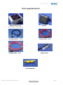
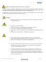
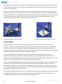
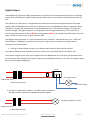
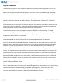
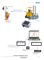
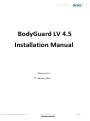
Orbit Communications Pty Ltd A.B.N. 95 107 441 869 BodyGuard LV 4.5 Installation Manual Revision 1.3 1st February 2012 BGLV 4.5 Installation Manual Rev 1.3 www.orbitcoms.com Page 1 Orbit Communications Pty Ltd A.B.N. 95 107 441 869 CONTENTS Parts Supplied with Kit Safety Precautions 3 4 Fuse Specification 5 Operating voltage Installation Wiring Diagram 5 LV Unit mounting 8 Speaker mounting 9 Antenna mounting 9 Power Supply 10 Digital Output 11 7 System Overview 12 Example of Calibration setup 13 Front Panel Controls 14 Power up sequence 14 Configuration Software Software Installation 15 Main Screen 16 Serial port settings 17 Connecting to BodyGuard Device 18 General Settings 19 Device Type Manager 20 Setting Detection Zones 21 History Log 22 Advanced Settings 23 Personnel TAG (pTAG) Page 2 Introduction 24 Operation and Fitting 24 Charging 25 www.orbitcoms.com BGLV 4.5 Installation Manual Rev 1.0 Orbit Communications Pty Ltd A.B.N. 95 107 441 869 Parts supplied with Kit Speaker BodyGuard LV unit BG400-LV (400MHz) or BG900-LV (900MHz) Wiring Harness – 1.5m Power Cable – 3m Antenna Kit Output Cable – 3m Fuse Assembly BGLV 4.5 Installation Manual Rev 1.3 www.orbitcoms.com Page 3 Orbit Communications Pty Ltd A.B.N. 95 107 441 869 Safety Precautions The following safety precautions must be observed whenever the Orbit BodyGuard system is in operation or in service. Failure to comply with these precautions violates the safety standards of the design, manufacture and intended use of the product Important BodyGuard proximity detection and warning system is intended to be an aid to the driver and is not intended in any way to replace existing safety processes or remove or minimise the driver’s diligence and/or duty of care. The Orbit wireless device system receives and transmits radio frequency energy while switched on, therefore interference can occur if the Orbit wireless device is located near TVs, radios, PCs or any inadequately shielded equipment. Due to the nature of wireless systems, transmission and reception of data can never be guaranteed. Data may be corrupted (i.e. Have errors) or be totally lost at certain times due to the environment, other machinery or malfunction of electronic components. Although significant loss of data are rare when wireless devices such as the Orbit BodyGuard system are used in a normal manner, Orbit’s BodyGuard system should not be used in situations, or in any manner, where failure to transmit or receive data could result in damage of any kind to the user or any other party, including but not limited to personal injury, death or loss of property. Orbit Communications Pty Ltd accepts no responsibility for damages of any kind resulting from errors in data transmitted or received using Orbit’s BodyGuard wireless device systems, or for the failure of the Orbit BodyGuard system to transmit or receive such data. Do not operate the Orbit BodyGuard system in areas where blasting is in progress, where explosive atmospheres may be present, near medical equipment, near life support equipment, or any equipment which may be susceptible to any form of radio interference, in such areas, Orbit’s BodyGuard system must be powered OFF. Do not operate Orbit BodyGuard system in any aircraft, whether the aircraft is on the ground or in flight. In an aircraft the Orbit BodyGuard system must be powered OFF. The information in Orbit Communications Pty Ltd documents are subject to change without notice and do not represent a commitment on the part of Orbit Communications Pty Ltd. Orbit Communications Pty Ltd and its affiliates specifically disclaim liability for any and all direct, indirect, special, general, incidental, consequential, punitive or exemplary damages including, but not limited to, loss of profits or revenue or anticipated profits or revenue arising out of the use or inability to use any Orbit Communications Pty Ltd product, even if Orbit Communications Pty Ltd and/or its affiliates have been advised of the possibility of such damages or they are foreseeable or for claims by any third party. Notwithstanding the foregoing, in no event shall Orbit Communications Pty Ltd and/or its affiliates aggregate liability arising under or in connection with the Orbit Communications Pty Ltd product, regardless of the number of events, occurrences or claims giving rise to liability, be in excess of the price paid by the purchaser for the Orbit Communications Pty Ltd product. Page 4 www.orbitcoms.com BGLV 4.5 Installation Manual Rev 1.0 Orbit Communications Pty Ltd A.B.N. 95 107 441 869 WEEE directive 2002/96/EC, disposal of old electronic equipment This product shall not be treated as household waste. It must be placed at an appropriate collection point for the recycling of electrical and electronic equipment. By ensuring the correct disposal of this equipment, it will help the environment and human’s health. The recycling will help to conserve the natural resources. Do NOT Dispose of Personnel TAG units (pTAGs) in a fire, furnace or other extreme heat source. These units contain batteries that may explode when exposed to extreme temperature. CAUTION Always remove battery connection before starting work on equipment to eliminate the risk of short circuit. Fuse type is 3AG, 2A, Slow-Blow. Make sure correct fuse is installed before applying power to system. Ensure fuse is replaced with specified type an rating only. Ensure power is removed from fuse before attempting to replace (Ignition switched OFF). Ensure cause of fuse “blowout” is fixed before replacing fuse. Ensure Power supply input voltage to BodyGuard LV unit is within the range specified for the model (10V DC to 28V DC for standard model), (22V DC to 72 VDC). Ensure that BG-LV enclosure is connected to chassis ground. Be careful to mount the BG-LV warning unit in such a manner as to ensure the unit does not obstruct the driver’s field of vision or interfere with driver movement required to safely operate the vehicle. The speaker should not be mounted close in a position where the sound can be clearly heard in event of a proximity detection but no so close as may prevent the driver from hearing other sounds or may potentially cause damage to hearing. It is recommended the speaker be placed a minimal distance of 300mm (12”) away from either of the operator’s ears. BGLV 4.5 Installation Manual Rev 1.3 www.orbitcoms.com Page 5 Orbit Communications Pty Ltd A.B.N. 95 107 441 869 Radio Frequency Radiation: The BodyGuard System produces very low levels of radio frequency signal. The signal level is less that 1mW (less than 1000 times less than the average mobile phone) and does not require any special attention to distances between the devices and personnel. Cleaning: Clean using a soft cloth dampened in mild detergent and water. Do NOT use chemicals or cleaners containing harsh materials such as benzene, xylene and acetone. Page 6 www.orbitcoms.com BGLV 4.5 Installation Manual Rev 1.0 Orbit Communications Pty Ltd A.B.N. 95 107 441 869 INSTALLATION Wiring Diagram (Negative Earth Chassis Assumed) 1 5 4 ~ 2 6 + 7 3 9 10 12 11 Legend 1. 2. 3. 4. 5. 6. BG-LV Unit Wiring Harness Antenna Kit Power Cable (2 way) Fuse Holder and Fuse Vehicle Ignition Switch BGLV 4.5 Installation Manual Rev 1.3 7. Vehicle Battery 8. Chassis Earth Connection 9. Speaker 10. RS232 to USB Adaptor (Only connect for programming) 11. Output Cable (3 way) 12. Laptop or Computer (Only used for programming) www.orbitcoms.com Page 7 8 Orbit Communications Pty Ltd A.B.N. 95 107 441 869 Mounting BG-LV unit The BG-LV unit should be mounted first to enable correct length of other cables to be determined. The unit should be located where the driver is able to see the visual warning (flashing red triangles) in the event of a proximity detection occurring. NOTE: The BG-LV unit should be mounted in a position that does not obstruct the operator’s view or interfere with the operator’s movement or ability to operate the vehicle in a safe manner. The BG-LV unit should be mounted firmly using optional magnetic mounts or a customer-supplied bracket that enables the unit to be bolted using the 4 mounting bolts at rear of the unit as shown below or mounting holes in the enclosure. The mounting bolts are 5mm (M5). The mounting bolts are located in a square that is 51mm x 51mm. Alternately the outer holes in the enclosure can be used for mounting. These are spaced 122mm x 60mm. Access to these holes is obtained by lifting off the outer plastic caps at each side of the enclosure. M5 Bolt x 4 M4 Hole x 4 C 51mm 60mm 109mm 51mm 122mm 138mm Underside View of BG-LV Enclosure for Mounting details Page 8 www.orbitcoms.com BGLV 4.5 Installation Manual Rev 1.0 Orbit Communications Pty Ltd A.B.N. 95 107 441 869 Mounting the Speaker The speaker is 8 Ohms and is rated at 3 Watts maximum power. It is supplied with 1.8m cable and terminated with a black plastic 3.5mm mono audio plug. The speaker is fitted with a swivel mounting bracket that allows mounting to a flat surface and can be swivelled to required angle. The mounting bracket requires 2 x M3 bolts. The distance between the mounting bolt centres is 38mm. The Speaker should be mounted in a convenient position that is close enough to alert the operator but not so close as to result in risk of damage to the ears. (The volume of the speaker is user-programming and can be set to a lower level, however in the event of incorrect programming or hardware fault the speaker should not be placed where it could cause damage to a persons’ hearing). Once the system has been installed, the speaker should be tested at full volume to ensure that at the distance installed, there is very little potential risk of damage to hearing. Move the speaker away if required. The speaker cable can be attached to the vehicle using nylon cable ties or clips. The cable should be placed inside split-loom tubing or similar electrical conduit if it is to be routed in proximity to heat source, dirt or grease etc (such as the engine bay). If the cable is longer than required then unused cable can be coiled up behind the speaker. The 3.5mm black plastic audio connector plugs into the gold metal audio connector of the wiring hardness. Antenna Mounting The antenna is the most critical element of the entire system. The very tip of the antenna is where the sensing occurs and the position of this point determines how effective the system operates in any given situation. There is no standard location for the antenna as each site and mix of vehicles and environment are different. Some guidelines can be given however an amount of trial needs to occur to find the best overall position. (Finding the best location is not a trivial task and normally requires some previous experience and technical expertise. The process may involve compromise between ideal coverage and alarms produced at further distances due to reflections off metal surfaces such as packing racks. Orbit Communications recommends on-site commissioning for this setup process). The BodyGuard system is designed to provide reduction of risk in a general area/zone and not the entire vehicle. Many applications have highest risk at the rear of the vehicle and therefore the antenna is mounted in such a manner as to provide best overall response in this region. Often the best mounting position is most counter-intuitive. For example : Placing the antenna at the front of a roof and hoping for more forward detection may result in a larger detection field behind the vehicle due to the manner in which the roof affects the signal (in this case intensifies the signal behind the vehicle). A good starting point is around 1.5 to 2m above ground at the rear and centre of the vehicle for rear detection. BGLV 4.5 Installation Manual Rev 1.3 www.orbitcoms.com Page 9 Orbit Communications Pty Ltd A.B.N. 95 107 441 869 The Antenna kit is supplied with a magnetic mounting bracket that allows the antenna to be mounted flat onto a horizontal surface such as a roof, or at right angles for vertical surfaces such as counter-balance at the rear of a forklift truck. Note: The antenna kit is provided with 8m cable that is terminated with a TNC connector that plugs into the TNC socket of the BG-LV unit. Any excess cable can be coiled up at any convenient location between antenna and BG-LV unit. The cable can be secured to the vehicle using nylon cable-ties or clips. If the cable is to be routed near heat sources, dirty or greasy areas (such as engine compartment) then it can be installed into split-loom tubing or similar electrical wiring conduit. Bracket mounting to vertical surface Bracket mounting for horizontal surface Power Supply The BodyGuard proximity detection and warning system obtains power from the vehicle’s battery. Typically, the power is connected after the vehicle ignition switch to ensure the system is switched OFF when not in use. (Note: for applications where the BodyGuard system must run continuously, such as when being used to alert other vehicles even when this particular vehicle is not being operated, the power should be connected to the battery-side of the ignition switch). The 2A, slow-blow 3AG fuse must be fitted in the positive wire of the Power Cable as shown. A weatherproof fuse holder is provided. The power cable wire must be fed through the end of the fuse holder and then crimped onto the fuse clip such that the fuse clip ends up inside the fuse holder. The same method is used for attaching the wire from the fuse to the ignition switch. Once the cable length between the BG-LV unit power connector and the ignition switch is determined, the cable can be cut to required length. The cable should be installed into split-loom tubing or electrical conduit if being routed near heat sources or dirty/greasy area such as engine compartment. Nylon cableties or clips can be used to secure cable to the vehicle. Ensure the NEGATIVE wire is connected securely to the negatively earthed chassis of the vehicle. The computer and RS232 Adaptor cable is only required when the system is being set up or the History Log is being downloaded. Once the system has been set up, both the adaptor cable and computer can be removed and are not necessary for ongoing operation of the system. Page 10 Rev 1.0 www.orbitcoms.com BGLV 4.5 Installation Manual Orbit Communications Pty Ltd A.B.N. 95 107 441 869 Digital Output The BodyGuard system has a Digital output that can be used to control external devices such as Flashing Lamps, Siren, LED indicator, Speed limiting system, Boom Gate or into another controller device such as PLC. The output is an “Open Drain” configuration that switches to the Common (Ground) side of the power supply inside the BodyGuard unit each time a detection occurs and BodyGuard alarm is activated. When the alarm is cleared, the output assumes a Floating (Open) state. The output is Voltage-Free (does not provide voltage). The Digital Output is not designed to control large loads directly, in the case of any current requirement greater than 100mA or voltage above 30V DC, the output should be used to control a relay coil that can then in turn control a heavier load. The Digital output connector is a 3-way automotive style connector. Two connections (+Ve – RED) and Digital Output – BROWN) are wired to this connector. Typical direct connection and relay control connection are shown below. 1. Driving an external device using a relay (Heavy load limited by Relay contact ratings) A protection diode must be installed across the relay coil as shown (Cathode to +Ve side of coil). The Positive voltage for the relay coil is supplied from the BodyGuard unit. The Relay coil therefore must be rated at the same voltage as the power supply into the BodyGuard unit (ie. 12V coil if 12V power supply, 24V coil if 24V supply voltage etc). Relay Controlled Device BodyGuard Loom 3-Way Plug and Socket Load Power Supply 2. Driving very light load (< 100mA, < 30 VDC). Direct-connection. Voltage to load is same level as BodyGuard power supply. Very light load (Buzzer or LED) BodyGuard Loom 3-Way Plug and Socket BGLV 4.5 Installation Manual Rev 1.3 www.orbitcoms.com Page 11 Orbit Communications Pty Ltd A.B.N. 95 107 441 869 System Overview The BodyGuard system has been designed to detect close proximity between any objects that are also fitted with a BodyGuard device. Apart from the pTAG units (which act like beacons and do NOT receive signals but only be detected by other types of BodyGuard devices), the BodyGuard units can detect other devices as well as being detectable by other devices. In order to be able to detect other BodyGuard units, each BodyGuard needs to be programmed with details of which units to detect and at what distance. This programming is referred to as “Calibration”. The calibration process involves placing the unit that is to be detected at the distance that is representative of the distance that the unit should set the alarm warning. If the detection zone is being set up at the rear of the vehicle then the object to be calibrated should be placed at the appropriate distance and almost directly behind the vehicle (representative of centre of the detection zone). The calibration process requires a Computer to plug into the RS232 serial port (9-way “D” shaped connector of wiring harness) of the BG-LV unit. The “Adaptor” that is supplied as part of the configuration kit converts the RS232 style connector to USB. (Details regarding installation of the software and programming appear later in this document). The device to be calibrated will be displayed on the computer screen. The user can select the device to be calibrated and add it to the list of devise that this particular BodyGuard unit will respond to. Once the device has been calibrated it should be moved around the vehicle and moved in and out of the detection zone to determine where the alarm trips at various points around the back of the vehicle (the shape will typically not be symmetrical). The user can then make adjustments in the software to the detection range until the best overall response is achieved. This may involve adjustments in both the calibration levels and the antenna location to obtain the most desired outcome. NOTE: When the vehicle moves, the detection zone will change shape and size as the system interacts with the environment. This modification of the zone cannot be controlled and is different for each site and combination of vehicles. After using the vehicle for a while, several more “tweaks” may be required. The compromise is typically between providing enough coverage in the area that is important but not setting the zone so large that devices can be detected far outside the required zone when the vehicle interacts with its environment. Example physical setup and method of calibration shown on next page. Software Calibration details appear later in Software Installation section. The system will not false alarm, it must receive valid signals from other devices in order to activate the alarm. What happens when the system picks up something outside the expected zone is the signal is being reflected off a metallic surface and being processed as appearing closer. A buffer “no-mans” zone, between where objects should be and where they should not be, should be made as large as possible to minimise annoyance to the operator by detection of devices due to reflections. Page 12 Rev 1.0 www.orbitcoms.com BGLV 4.5 Installation Manual Orbit Communications Pty Ltd A.B.N. 95 107 441 869 pTAG, ID = 486 Required detection distance 1. Object placed at required distance Detected Devices TYPE pTAG ID 486 Calibrated Devices LEVEL 577 2. Show Devices in Area 3. Select appropriate device from List TYPE pTAG ID 486 LEVEL 577 >> 4. Move selected device to Calibration List Save … 5. Save Calibration list List when done Example of Calibration Setup BGLV 4.5 Installation Manual Rev 1.3 www.orbitcoms.com Page 13 Orbit Communications Pty Ltd A.B.N. 95 107 441 869 BG-LV Front Panel Controls MUTE Detect Power RED Triangles: Visual warning. Top/Bottom and Left/Right pairs flash alternately during alarm condition MUTE: This function is used to silence the audible alarm when the operator may wish to converse with a person standing close to the vehicle. If “Mute” is pressed while the alarm is active then the audible alarm (from speaker) is silenced but visual alarm continues. When the person moves away from the vehicle then the audible alarm resets automatically resets when the alarm ceases. In the event another object enters the detection zone while the alarm is silenced, it will automatically reset and sound the audible alarm to indicate a new risk of collision. DETECT: The GREEN “Detect” LED will light whenever ANY BodyGuard object is detected at any distance. The function of this LED is to show the system is operating correctly and receiving signals. NOTE: The Detect LED will ONLY function when the Receiver is enabled (programmable). POWER: The GREEN “Power” LED will light when the unit has DC power applied. Start-up sequence: Whenever the BG-LV unit is powered up the 4 RED triangles will flash several times and the speaker will emit several beeps. Note: The Volume of the speaker is controlled by the configuration programming software and is not adjustable by the operator. Page 14 Rev 1.0 www.orbitcoms.com BGLV 4.5 Installation Manual Orbit Communications Pty Ltd A.B.N. 95 107 441 869 Software Installation The BodyGuard configuration software is supplied as part of the configuration kit (Kit includes Software with site license and RS232 to USB convertor). The Software is available online at http://orbitcoms.com/updates/bodyguard45/Setup.htm The system requires Windows XP or Windows 7 to operate. Connection to the internet is required only during first installation. Once installed, the software will check the internet for new versions each time it is run (if the computer has internet connection available). Install the software by copying the file “BG45 Setup” and running the file from the copied location. In the event that a dialog box appears as shown below, click “Run”. The program will automatically verify the location of the setup software, create a short-cut icon on the computer desktop and run the program. Icon on Desktop BGLV 4.5 Installation Manual Rev 1.3 www.orbitcoms.com Page 15 Orbit Communications Pty Ltd A.B.N. 95 107 441 869 Using Configuration Software Every BodyGuard device must be set up using the configuration software before it can be used effectively. Before a BodyGuard device can detect another unit, the details of the other unit must be programmed into the device. This is referred to as “Calibration”. Each BodyGuard unit must be given an Identification to enable other units to be able to be calibrated with the particular unit to tell it apart from other BodyGuard units. The configuration software enables parameters to be set up for a particular device to enable it to be calibrated with other devices, it enables calibration for this device to other devices and enables download of the Near-miss history log that keeps the last 2000 time/date-stamped events (devices detected entering or leaving the detection zone) in memory. When the configuration software runs, the main screen will be displayed Software Version Top Menu Function TABS Buzzer Test Button Enable Buttons Buzzer Volume knob Save Button Status Bar The first step is to select the appropriate serial port. The serial port can be selected by clicking “Serial Port” from the Top Menu. A list of available serial ports will be displayed. Use the arrow key to open the list and then select the appropriate port and click “OK’. Page 16 Rev 1.0 www.orbitcoms.com BGLV 4.5 Installation Manual Orbit Communications Pty Ltd A.B.N. 95 107 441 869 Connecting to BodyGuard Device To connect to a BodyGuard unit, the Computer or laptop must be connected to the Device using the 9-way Serial connector on the BodyGuard wiring harness. Click “Connect to BodyGuard” to retrieve the units settings. A small dialog box will indicate the software has successfully connected to a BodyGuard unit and identify the Type of unit and its ID number. (In this case a Vehicle Type with ID = 2). General Settings The current Time and Date of the attached BodyGuard clock will be displayed. Note: The time and date of the BodyGuard unit will be updated to be the same as the computer running the software when the “Save Settings” button is pressed. The ID can be changed as desired by entering a number between 1 and 65535 in the “BodyGuard ID” box. The TYPE of BodyGuard device can be selected from the Pull Down menu box next to “BodyGuard Type”. A BodyGuard unit can be assigned as 1 of 255 types. The Types are user defined tags that are set up in “Manage Device Types” TAB. This enables vehicles or objects of the same type to be grouped together or each individual device can be given its own type (For instance, the type may be a vehicle registration number or driver’s name or it may be a type of vehicle such as Forklift, Truck, Crane etc). The “Hold Time” is user programmable from 1 second to 255 seconds. This is normally set to 1 second for most applications. When a vehicle is right on the edge of a detection zone or moving around within a zone, it may from time to time receive a lower signal and drop out and then come back on when it picks up the signal again. The Hold Time keeps the alarm activated for the amount of time selected (after detection ceases), if detection occurs before the Hold Time expires then the alarm will remain active until no detection occurs for greater than this Hod Time. The aim of this function is to prevent “chattering” where the alarm is activated and de-activated when on the edge of the dtection zone. It can also be used to advantage for a fixed unit or boom gate type situation to hold the gate closed or lamp flashing for several seconds after the vehicle has passed to ensure the area is clear. BGLV 4.5 Installation Manual Rev 1.3 www.orbitcoms.com Page 17 Orbit Communications Pty Ltd A.B.N. 95 107 441 869 The “Buzzer Vol” knob adjusts the volume of the alarm buzzer heard in the speaker. The buzzer volume can be adjusted and then tested by clicking “Test Buzzer Volume” Button. NOTE: The new buzzer volume will not be saved in the BodyGuard memory until “Save Settings” button is clicked. The “TRANSMITTER” switch is used to enable and disable the BodyGuard transmitter. Typically the transmitter is tyurned OFF when the unit is to be a receive only device and not to be picked up by other objects (Such as afixed warning lamp application). For this unit to be detected by other BodyGuard devices, the Transmitter must be ON (LED on switch is Green when ON and Red when OFF). In order to detect other BodyGuard devices the ‘RECEIVER’ switch must be ON. This is typically turned off only for specific devices such as a hazard warning beacon. When the receiver is switched OFF, no detections will occur and nothing can be calibrated with this unit. The “ALARM” enables and disables the audible and visual alarm. This is used to temporarily disable the alarm to avoid annoyance when calibrating this unit to another device. The “ALARM” switch must be ON in order for proximity detection occurance to produce visual and audible warning. Device TYPE Manager This TAB enables user-defined TYPES to be defined. Up to 255 TYPES can be defined. Selecting an existing type in the list on the left will highlight the type and indicate the type selected next to “Selected TYPE”. Once highlighted, the Type can be deleted by clicking ‘Delete Selected TYPE” or changed by selecting “Edit Selected Type”. Note: The pTAG type cannot be removed or edited, the TAG type is pre-defined and fixed. In addition to the pTAG, at least one other type must exist to enable the attached device to be assigned as something. The title given to the type will appear in the history log as well as on the main page when connecting to a BodyGuard unit. Once the desired additions, deletions and changes have been made, the “Save Changes” button must be clicked to save. Note: The Device TYPE list is saved on the computer. The actual type saved in the BodyGuard unit is a number that represents the Type and when connected to the computer. If more than 1 computer is being used to set up BodyGuard systems then the device list details should be set up the same for other computers to ensure types are compatible across the organisation. Page 18 Rev 1.0 www.orbitcoms.com BGLV 4.5 Installation Manual Orbit Communications Pty Ltd A.B.N. 95 107 441 869 Setting Detection Zones (Calibration) When selecting this TAB, any existing devices with which thisunit has been calibrated will we displayed in the righthand list. This is the calibration list. In the case above the device has a detection zone set up between this unit and a Personnel TAG (pTAG) whose ID is 380. When this BodyGuard unit detects a pTAG with ID=380 and the level exceeds 380 then the alarm will be activate (as long as ALARM switch is on), a record will be saved into the History Log with Time and Date that the detection occurred and also identifies it as pTAG with ID = 380 and whether the device was detected entering or leaving the zone. To add new devices to the Calibration List, click “Show Devices in Area”. Any other BodyGuard devices that are in the general area (normally up to 50-100m) will be displayed on the left-hand list (detection list). The Tpe of device, its ID and the level will be displayed for each. The method of calibration is that one or more devies are physically located at the required distance fron this vehicle. The list of devices is obtain using “Show Devices in Area” function. All devices to be added to the calibration list are then selected and moved to the right hand list using the “>>” Button. Devices can be selected 1 at a time and moved across or a group of contiguous devices can be selected by clicking first item desired and then hold “SHIFT” key while clicking last item desired. Once selected, click “>>” to move to calibration list. Also, a group of any specific devices can be selected by selecting the first device and then holding “CONTROL” key while selecting others and finally clicking “>>” to add to the calibration list. The devices moved to the calibration list will NOT be saved to the BodyGuard unit until the “Save to BodyGuard” button is clicked. It is suggested when calibrating devices that the “Get Devices in Area” is clicked several times to ensure the calibration value represents a fair average of level over time. Once a device is moved to the calibration list the level can be fine tuned. A specific new value can be entered manually by double-clicking the device row in the calibration list and entering a number or by clicking “Further” button to set a smaller value that causes the alarm to trip further away (larger detection zone) to “Nearer” button to cause trip to occur closer (small detection zone). Some experimentation is recommend as follows: Set up calibration at distance required. BGLV 4.5 Installation Manual Rev 1.3 www.orbitcoms.com Page 19 Orbit Communications Pty Ltd A.B.N. 95 107 441 869 Move calibrated device toward and away from this unit to determine where the alarm is being tripped. Fine tune the level for this device to caus edevice to trip alarm at required distance. Once this is done, the calibrated device can be moved around the vehicle in the vicinity of the required zone to determine where/if blind spots etc exist. The system can then be fine tuned again for best overall solution. When systems are being installed onto the same type of vehicle and all interact with each other, there is a shortcut for calibration. (As long as the vehicles are the same type and the antenna installation is in the same place). Once one unit is set up. Save the settings to the BodyGuard unit and then click “Export” to save these settings to disk. Another BodyGuard then can be connected and the “Import” button is used to copy the exported calibration list directly into the new unit calibration list. Finally, devices can be added to the calibration list manually (without requirement for the device to be available at the time). To add a device History Log The BodyGuard device will store up to the last 2000 events detected. To down load the History log from the BodyGuard device to the computer click “Download Log from BodyGuard”. The list of records will be displayed in the Histroy Log List. Each record is displayed as a row in the list and displays the TYPE (as programmed into those devices where the text shown is the text entered for these types in the Type Management TAB), the ID of the specif unit detected, the Level at which the detection occurred, Date and Time and finally whether the device was detected entering (“Trip”) or leaving (“Clear”) the detection zone. The Status at bottom centre of the screen shows the TYPE of the device connected to the computer, its ID and how many records are contained in the History Log. When the system resumes operation further log events will be appened to the end of the log and once 2000 records have been reached further events begin to write over the oldes log records (wraps around to first location again and cycles in this manner). To clear the log of all records and start recording from 0 again, click “Clear BodyGuard Log”. Page 20 Rev 1.0 www.orbitcoms.com BGLV 4.5 Installation Manual Orbit Communications Pty Ltd A.B.N. 95 107 441 869 The power of the History Log is obtained when the records are analysed to identify trouble spots (large number of detections around a date/time, vehicle type, specific vehicle etc). The log can be exported to the computer as an Excel file. Click “Export” and select a file name to save the file to disk. This file can then be opened in Excel and analysed using the powered filtering and reporting functions in that application (or similar software that accept cvs formatted files). Advanced Settings These settings are not to be changed by the user. They are specified settings that are set up in the factory and can later be modified by authorised Orbit service technicians. BGLV 4.5 Installation Manual Rev 1.3 www.orbitcoms.com Page 21 Orbit Communications Pty Ltd A.B.N. 95 107 441 869 Personnel TAG (pTAG) Introduction The BodyGuard Personnel TAG unit (pTAG) is a component of the BodyGuard proximity detection and warning system. Personnel that have bend fitted with a pTAG unit can be detected by moving objects (such as trucks and forklifts) that have been fitted with BodyGuard detection units. Fitting and Operating The pTAG unit should be worn on a Hard-Hat wherever possible for best performance. (The TAG will not perform well if worn on belt or in a pocket where the body can obstruct the signal) An Adaptor clip is supplied that press fits into the expansion slots on the side of the hard-hat. The pTAG can then easily be clipped into place or removed. Alternately, the pTAG may be attached to an object using Velcro. The higher on the body the pTAG is located, the better the performance. It is NOT advised to be located in a pocket or on a belt where the body can obstruct the signal. A clear line of sight between the pTAG antenna and antenna of any BodyGuard detector unit will result in best overall performance. The pTAG should be orientated such that the antenna is vertical and charging pins facing downward. The pTAG is NOT fully waterproof. The top and sides can generally cope with light rain however the slot underneath where the battery charge terminals are located is not tolerant to water. If the unit is to be used outdoors in wet conditions, it is recommended the unit be placed into a protective plastic/rubber or other non-conductive sleeve. The pTAG unit does not have an ON /OFF switch, the unit operates continuously. During normal operation, a RED Led on the front of the pTAG unit will blink approximately every 2-3 seconds. The pTAG is powered by built-in re-chargeable Lithium Ion (Li-Ion) batteries. Though the pTAG unit is expected to run up to 7 days on a full charge it is recommended to recharge the unit at least every 2-3 days. The pTAG battery pack is protected against reverse voltage, over voltage, short circuit, over current and low voltage. In the event of any of these conditions being present, the battery protection circuit will activate and automatically disconnect the battery from the circuit. The RED LED on the front panel of the pTAG will no longer blink. Normal operation can be restored by placing the pTAG unit on charge. Page 22 Rev 1.0 www.orbitcoms.com BGLV 4.5 Installation Manual Orbit Communications Pty Ltd A.B.N. 95 107 441 869 Charging the pTAG 1. Plug the supplied mains power pack 2.1mm round connector into rear of BodyGuard charger unit 2. Plug supplied mains power pack into mains outlet (The Green “POWER” Led should be on solid and the Green “STATUS” Led should be off or a slight flicker may be visible). 3. Remove the hard-hat Adaptor clip from the back of the pTAG unit (if fitted) 4. Place the pTAG unit into charger cradle (Label on pTAG unit facing forward). The Green “STATUS” Led should glow solid. Important: Ensure pTAG is placed with label facing forward to avoid possible damage to charger unit. 5. Once charging is complete (Approx. 2-3 hours) the Green “STATUS” Led will switch OFF. pTAG unit pTAG lowers in here with Label toward Leds) Charge Pins Power Pack Adaptor Clip “POWER” Led Status Led 2.1mm Plug BGLV 4.5 Installation Manual Rev 1.3 www.orbitcoms.com USA Version Page 23 Orbit Communications Pty Ltd A.B.N. 95 107 441 869 Fixed Unit Introduction The BodyGuard Fixed unit is typically used to provide a warning to personnel when a vehicle or machine is operating close to personnel. The can be used to control a flashing strobe warning light, traffic control signal, audible warning device or other equipment as desired. Page 24 Rev 1.0 www.orbitcoms.com BGLV 4.5 Installation Manual