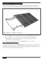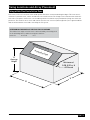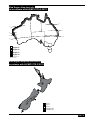
1
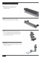
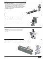
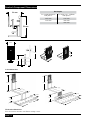
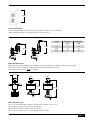
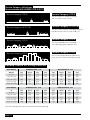
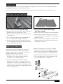
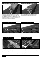
Solar Panel Mounting System
Rooftop Installation Manual
www.sunlock.com.au
Version 3, updated May 2011
Contents
Introduction..............................................................................................................3
Safety and Installer Responsibilities........................................................................4
Handling and Installing SunLock................................................................................... 4
Wind and Climate Design............................................................................................... 4
Technical Specifications............................................................................................5
Applications.................................................................................................................... 5
Features.......................................................................................................................... 5
Technical Specifications................................................................................................. 5
Before Installing.......................................................................................................6
Receipt of Goods............................................................................................................. 6
Tools Required for Installation....................................................................................... 7
SunLock Component Descriptions................................................................................. 8
SunLock Component Dimensions.................................................................................. 10
Designing Your Framing System...............................................................................12
Procedure to Select Rail Spacing................................................................................... 12
Fixing Locations and Array Placement.....................................................................13
Fixing within Roof Installation Zone............................................................................... 13
Procedure to Select Fixing Centres................................................................................ 14
Worked Example............................................................................................................. 14
Wind Region Map Australia (in accordance with AS/NZS1170.2.2011).......................... 15
Wind Region Map New Zealand (in accordance with AS/NZS1170.2.2011)........................ 15
Terrain Category Definitions (in accordance with AS/NZS1170.2.2011)........................ 16
Lookup Tables for Fixing Centres.............................................................................16
Installation...............................................................................................................17
Installing L-Feet on Steel Roofs..................................................................................... 17
Installing Tile Brackets................................................................................................... 17
Maintenance and Cleaning........................................................................................20
Warranty Conditions.................................................................................................20
References...............................................................................................................20
Contact Details.........................................................................................................21
Certificate of Compliance.........................................................................................21
Introduction
Thank you for choosing the SunLock solar panel roof mounting system. Made from custom-built aluminium
extrusions and components, SunLock’s streamlined design and improved frame strength greatly simplify
solar panel installation.
Offering a high level of adjustability for module width and depth SunLock’s versatile design makes it suitable for
a wide variety of building types and zones including residential, commercial and remote environments.
SunLock is backed by a 10-year warranty and is compliant with the Australian/New Zealand Standard on
Wind Actions (AS/NZS1170.2.2011).
c
m
WARNING: indicates a potentially hazardous situation which, if not avoided, could
result in death or serious injury. This symbol is not used for hazards relating to
property damage unless there is also a risk of personal injury to this level.
CAUTION: indicates a potentially hazardous situation which, if not avoided,
may result in minor or moderate injury. It may also be used to draw attention
to unsafe practices that may cause damage to property.
PAGE | 3
Safety and Installer Responsibilities
m
INSTALLATION OF THIS PRODUCT IS TO BE PERFORMED ONLY BY
PROFESSIONALLY TRAINED INSTALLERS.
Any attempt by an unqualified person to install this product could result in
death or serious injury.
Handling and Installing SunLock
It is critically important that safety practices are observed when installing SunLock.
» Do not throw or roughly handle any SunLock components.
» Do not bring SunLock into contact with sharp or heavy objects.
» Do not modify SunLock components in any way. The exchange of bolts, drilling of holes, bending or
any other physical changes not described in standard installation procedure will void the warranty.
» It is the installer’s responsibility to verify the integrity of the structure to which SunLock is fixed. Roofs or structures with rotten/rusted bearers, undersized bearers, excessively spaced bearers, or any other unsuitable substructure cannot be used with SunLock, and installation on such structures
will void the warranty, and could result in death or serious injury.
Wind and Climate Design
AS/NZS1170.2.2011 provides guidance on determining the wind pressures applicable to your SunLock install site,
taking into account roof shape and geographic location. Sufficient guidance is given in this document, but you
may wish to procure a copy of these standards if your company installs Australia/New Zealand wide.
» REMEMBER average wind speeds are higher for structures mounted closer to the roof perimeter zone (edge). Refer to ‘Fixing within Roof Installation Zone’ for more information)
» Make sure your installation complies with local and national building codes. Take into account relevant design
parameters (wind speed, exposure and topographic factor) when determining the loading for the installation.
» If alternative fasteners are used to fix the framing to the roof (assuming supplied fasteners are unsuitable
for any reason), all screw fasteners must conform to corrosion resistance Class 4 Australian Standard
AS3566 and be of equal or greater strength to those supplied with your SunLock order.
PAGE | 4
Technical Specifications
Applications
» Commercial and residential buildings
» Marine applications and remote areas
Features
» 6106-T6 Aluminium extrusion
» Ripple design on L-foot and tile brackets increases joint strength
» Suitable for buildings up to 200m in height
» Suitable for roof slopes in the range from 0º to 65º
» Significantly higher strength-to-weight ratio than other framing products, providing improved efficiency due to greater frame spans, inherent corrosion resistance resulting in low ongoing maintenance and an extended product life.
» Complies with Australian/New Zealand Standard on Wind Actions, AS/NZS1170.2.2011
» Optional anodised finish (standard is mill finish)
» Australian design and manufacture
Technical Specifications
Material
Tensile strength
6106-T6 Aluminium Extruded
Ultimate
235 MPa
Yield
210 MPa
Module thickness
30 to 58mm
Roof slope
0° to 65°
Building height
Up to 200m
Mounting structure
Timber or steel
Roof types
Flat or pitched steel and tile (concrete or terracotta)
PAGE | 5
Before Installing
m
CAUTION: Refer to the section ‘Designing Your Framing System’ before attempting
installation. Failure to correctly establish the requirements of the proposed installation
site is dangerous and will void the framing warranty.
Receipt of Goods
Check that the SunLock equipment is undamaged and that the order is complete. Check for correct quantities of
the following items:
» Rails: slightly more than twice the length of the proposed solar array in linear metres
» End clamps: a minimum of 4 per row of panels (fitted at the ends)
» Mid clamps: 2 for every gap between neighbouring panels, e.g. 10 for an array of 6 panels in a single row
» Roof Interface Legs: at least 2 for each panel; L-feet, roof screws and isolation washers for steel roof
interfaces; tile brackets and rafter screws for tile roofs. Refer to Procedure to Select Fixing Centres (page 14)
PAGE | 6
Tools Required for Installation
» T-bar Allen Key or 6mm hexagonal driver bit. If using a 6mm driver bit, make sure the cordless power tool used for driving has a hand-tight clutch setting and a
fine (soft) impact drive to prevent damage to the fragile
glass panels and threads on the SunLock framing.
» Drill or impact driver for driving roof material fixings.
» Gloves for handling SunLock framing (aluminium can develop sharp corners).
» For terracotta tile roof installation, an angle grinder fitted with a continuous edge diamond tipped tile-cutting blade; gloves, hearing protection, a face protection mask, and a suitably rated breathing protection mask
for all people in proximity of grinding.
PAGE | 7
SunLock Component Descriptions
1. Rails hold each panel row and are custom designed and Australian made 6106-T6
extruded aluminium.
2. Joiners extend SunLock Rails to any length as required by the quantity or width of the solar panels.
3. L-foot roof mounts secure the railing to steel roofs. Refer to loading tables (below) for spacing information. The L-foot is made from aluminium and must be used with the supplied isolation washer to prevent galvanic corrosion with the roof material.
4. Tile brackets fix the railing to the rafters below a tile roof and ensure a waterproof finish. Each tile bracket includes two 50mm roofing screws.
PAGE | 8
5. Adjustable tile brackets provide a simple and adaptable method
for attaching SunLock framing to tile roofs. Additional features
allow adjustment of the elevation and side position of the
bracket to provide a closer fit for different tile batten heights,
tile profiles, and tile positions. Each tile bracket includes two 50mm roofing screws.
6. End clamps hold the edge of each ‘end’ panel and are fully height adjustable to accommodate solar panels of any thickness (between 30 and 58mm). These are fastened with a 6mm hex driver/Allen key.
7. Mid clamps fit between two panels and hold the panels to the rails. These are fastened with a 6mm hex driver/
Allen key.
8. EarthLock system comprises the EarthLock washer and the EarthLock lug.
This system provides earth continuity from each panel frame to the rail, allowing
the quick and effective connection of the array to an earthing cable if required.
PAGE | 9
SunLock Component Dimensions
Rail lengths
30 mm
3410 mm
For standard 808mm
wide panels
For wider 990 - 1005mm
wide panels
2600 mm
2100 mm
3410 mm
3200 mm
4200 mm
2600
mm
53 mm
1705 mm
40 mm
80 mm
28 mm
75 mm
50 mm
L-foot dimensions
115 mm
115 mm
101
120
mm
mm
69 mm
50 mm
50 mm
41 mm
m
7m
16
Tile bracket dimensions
Each tile bracket includes two 50mm roofing screws.
PAGE | 10
181
mm
38 mm
Fixed leg end clamp
The fixed height end clamp suits the growing number of panels with a standard
38mm height and simplifies and speeds up the install process
Clamp
50 mm
32 mm
Minimum
Maximum
mm
mm
Low
30
42
Med
34
46
High
46
58
End clamp dimensions
Adjustable end clamps allow the easy modification of the clamp to suit almost any panel frame height.
Diagram shows the ‘medium’ clamp in the minimum and maximum positions.
Note: Minimum of two fins must be engaged.
18 mm
1a
1b
50 mm
60 mm
Mid clamp dimensions
There are two mid clamp assemblies, with different lengths of cap screw.
1a. suitable for 30 mm - 40 mm thick solar panels
1b. suitable for 40 mm - 50 mm thick solar panels
Note: Other panel thickness accommodated by special orders
PAGE | 11
Designing Your Framing System
The installation site, roof height, roof material, roof angle, the size and quantity of solar panels and the number
of module rows used will determine the dimensions, quantity and layout of framing components required for
installation. This section of the document should be used before installation to determine critical job specifications.
3
Z
2
X
Y
1
4
W
1 Rail
2 End clamp
3 Mid clamp
4 L-foot
» The term ‘spacing’ refers to the distance between the parallel rails (dimension Y on the figure above). The spacing of the rails is determined by the spacing of the battens/purlins beneath.
» The term ‘centres’ refers to the distance between mounting points of the roof (dimension X).
The distance between centres can be reduced (and therefore the number of points of contact
increased) to increase the wind load rating.
The overhang between the L-foot and the end of the rail (dimension W) must be less than 200mm.
Procedure to Select Rail Spacing
The length of overhang from rail to panel end (dimension Z) should not be less than 10% nor exceed 25% of the
total length of the panel. Always refer to the solar panel manufacturers’s product installation manual. For tin roof
installations where the purlin spacing is less than 750mm, a third rail should be used in the middle of the outer
rails to avoid unevenly increasing the wind load on the purlins.
PAGE | 12
Fixing Locations and Array Placement
Fixing within Roof Installation Zone
Inner areas of the roof encounter lower wind speeds than those encountered along the edges. This inner area is
called the ‘installation zone’, and is considered a safe install location. The fixings of the frame must be within this
zone. Note: The panels themselves can extend beyond the installation zone provided the fixings are within the
perimeter. The installer must check and confirm that the roof structure (battens/purlins) are in good condition
and can withstand the extra loads created by the PV system.
Determining the width of the edge exclusion zone
The width of the edge exclusion zone is determined by calculating each
of the following values, and then using the smallest:
» 0.2 x B
» 0.2 x D
»H
Edg
e Ex
clus
ion
Zon
e
Inst
alla
tion
Zon
e
‘H’
Average
Height
Minimum of
0.2B, 0.2D or H
All Round
‘D’
‘B’
PAGE | 13
Procedure to Select Fixing Centres
1. Assess and record your terrain category (page 16) for the installation site.
2. Use these results to determine the fixing centres from the Lookup Tables for Fixing Centres (page 16).
You will also need to know building height and roof area dimensions to establish the edge exclusion zone when looking up the fixing centre value – this is covered in the section Fixing within Roof Installation
Zone (page 13). The edge exclusion zone specifies the minimum distance fixings can be installed from
the edge of the roof.
3. Verify that the substructure and attachment method is sound and suitable, as explained in Installation (page 17). Note: if using screws other than the provided, all screw fasteners must conform to corrosion resistance Class 4 Australian Standard 3566.
Note: A topographic factor of MT = 1.0 has been assumed, which applies for buildings on level (or near
level) ground. The spacing value refers to the maximum allowed spacing.
Worked Example
1. Assume the installation site is a house in Toorak, Victoria. This is determined as wind region A through
the use of the wind region maps (page 15).
2. Terrain falls within Category 3 (TC3) due to the presence of numerous closely spaced obstructions (buildings) 3m to 5m high in the residential building zone (page 16).
3. Check the planned array installation dimensions are not within the edge exclusion zone of the roof.
4. Assuming the example roof is flat steel, tilt legs will be required. Refer to SunLock elevated mounting installation manual for more information
After determining the building height, wind region and terrain category, refer to the Lookup Tables for Fixing
Centres (page 16) to determine appropriate fixing centre values, e.g. the arrow below indicates a measurement
of 1140mm for centres.
Calculated Fixing Centres
Topographic region = 1.0
ROOF HEIGHT
WIND REGION A - mm
WIND REGION B - mm
Metres
TC2
TC2.5
TC3
TC4
TC2
TC2.5
TC3
TC4
H < 10
790
940
1140
1400
490
580
710
870
10 < H <20
670
770
890
1400
420
480
550
870
20 < H <40
580
650
730
1090
360
400
360
680
40 < H <100
510
540
580
740
N/A
N/A
N/A
460
100 < H <200
470
490
510
580
N/A
N/A
N/A
360
PAGE | 14
Wind Region Map Australia
(in accordance with AS/NZS1170.2.2011)
20˚
20˚
25˚
25˚
27˚
30˚
30˚
Region A
Region B
Region C
Region D
Wind regions based on
AS1170.2 - 2002
Wind region A is wind speeds up to 41ms (W41)
Wind region B is wind speeds up to 54ms (W54)
Wind region C is wind speeds up to 58ms (W58)
Wind Region Map New Zealand (in
accordance with AS/NZS1170.2.2011)
Region A6
Region A7
Region W
Lee Multiplier (NW)
Lee Multiplier (SE)
PAGE | 15
Terrain Category Definitions
(in accordance with AS/NZS1170.2.2011)
Terrain Category 2 (TC2)
Terrain Category 2 (TC2)
Site near water or cleared rural land
with few obstructions to wind.
Terrain Category 2.5 (TC2.5)
Terrain Category 2.5 (TC2.5)
Site near scattered trees or buildings and near
low obstructions such as crops, fields, etc.
Terrain Category 3 (TC3)
Terrain Category 3 (TC3)
Site surrounded by trees or buildings
3m to 5m high (typical suburban site).
Terrain Category 4 (TC4)
Terrain Category 4 (TC4)
Site located in highly built up industrial or
inner city areas (10m to 30m obstructions).
Lookup Tables for Fixing Centres
ROOF HEIGHT
WIND REGION A - mm
WIND REGION B - mm
Metres
TC2
TC2.5
TC3
TC4
TC2
TC2.5
TC3
TC4
H < 10
790
940
1140
1400
490
580
710
870
10 < H <20
670
770
890
1400
420
480
550
870
20 < H <40
580
650
730
1090
360
400
360
680
40 < H <100
510
540
580
740
N/A
N/A
N/A
460
100 < H <200
470
490
510
580
N/A
N/A
N/A
360
ROOF HEIGHT
WIND REGION C - mm
WIND REGION W - mm
m
TC2
TC2.5
TC3
TC4
TC2
TC2.5
TC3
TC4
H < 10
N/A
N/A
420
420
610
730
890
1090
10 < H <20
N/A
N/A
N/A
N/A
520
600
690
1090
20 < H <40
N/A
N/A
N/A
N/A
450
500
560
850
40 < H <100
N/A
N/A
N/A
N/A
400
420
450
580
100 < H <200
N/A
N/A
N/A
N/A
370
380
400
450
Note: The spacing value refers to the maximum allowed spacing.
PAGE | 16
Installation
Start any roof/structure installation by marking the fixing points at the calculated centres and spacing along
the proposed length of the array (in a parallel row).
Note: A roof interface leg (L-foot or tile bracket) should be mounted within 200mm of each end of each rail.
Installing L-Feet on Steel Roofs
L-foot fits to
the crest
a. For a steel roof with exposed fixings
1. Determine where the roof mounts will be positioned based on position of existing roof screws.
2. Do not remove existing roof screws. Instead, install on unused crest.
3. Fix L-feet in place and fix with the upright part of the ‘L’ facing towards the ridge of the roof.
4. S
ecure the L-foot roof mounts with the roof screws.
Use the supplied isolation washers between the base
of the L-foot and the roof surface.
b. For a steel roof with hidden fixings
(clip-type roofing)
1. Lift the sheets of steel to expose the structure beneath.
2. Using a marker, mark out the precise locations of
the structure below the roofing material and clip the roof back in place.
3. Place L-feet on the markings and screw down with supplied isolation washers between the base of the foot and the roof surface.
Installing Tile Brackets
Installation of the Sunlock Adjustable Tile Bracket
requires no special tools - only a 13mm socket/
spanner and the 6mm internal hex driver/Allen key
normally used for SunLock framing.
» Attach the tile brackets to the rafters using the supplied screws. To prevent splitting the timber,
pre-drill the screw holes at an inward facing angle. This is especially important for hardwood rafters.
»E
xpose the timber rafters where the SunLock Tile Brackets are to be attached by sliding or
removing tiles at a suitable spacing
» Move the tiles back into place. Attach the SunLock rails to the Adjustable Tile Bracket uprights, and your framing installation is complete.
» Loosely assemble the tile brackets ready for adjustment. Place the first tile bracket on a rafter and adjust the elevation to a low and flush fit. Use a 13mm socket to secure the bolt assembly. Generally, the other brackets on the roof can be adjusted to the same elevation position.
115 mm
120
mm
69 mm
50 mm
181
mm
PAGE | 17
1. Connecting Rail to Roof Mounts
2. Connecting Rail to Roof Mounts
Connect the rail to the roof mounts by inserting the
roof mount keylock into the rail channel. Make sure
the ridged rail surface faces the ridged surface of roof
attachments. Fasten the cap screw on the keylock 2-3
turns to loosely hold the rail in position.
The rail can be adjusted vertically within the roof
attachment slot when bolts are loosely fastened.
3. Connecting Multiple Rails
4. Connecting Multiple Rails
Join rail segments by inserting the rail joiner into the
rail channel.
Fasten cap screws to secure.
5. Installing End Clamps
6. Installing Mid Clamps
Insert keylock of the end clamp into the rail channel.
Using a 6mm hex driver/Allen key, secure the first solar
panel to the railing starting as close to the end of the
row as possible. A minimum of 50mm between the end
of the rail and edge of the first solar panel is required.
Insert the keylock of the mid clamp into the rail
channel and position the clamp against the first panel
frame. Hand-tighten the screw 2-3 turns to loosely
hold the clamp in position. If EarthLock washers are
used, they should be placed between the SunLock rail
and the frame of the panel.
PAGE | 18
7. Installing Mid Clamps
8. Check Alignment of the Array
Slide second panel firmly into place against the
mid clamps and fasten bolts.
After fixing the first 2 panels, check that the array is
straight. If there appears to be a deviation from square
(e.g. if the ridge cap shows the row to be falling or
rising slightly), readjust the panels until they appear
square with the roof. Alternatively, measure the
distance from the rail to the edge of the panel.
9. Continue Installing Mid Clamps
10. Install End Clamps
Continue to clamp the neighbouring panels in the array
to the rails.
Finish the array row by securing the remaining two
end clamps. You should have a minimum of 50mm
clearance between the edge of the last panel and the
end of the rail. Tighten all bolts to secure the panels.
11. EarthLock Lug
Fasten the EarthLock Lug directly to a SunLock rail
by placing the insert key in the rail and tightening the
cap screw.
PAGE | 19
Maintenance and Cleaning
6106-T6 aluminium is largely maintenance free. Only in highly polluted or marine conditions is rinsing with
clean water required, during scheduled panel cleaning.
Warranty Conditions
Energy Matters Pty Ltd (trading as Energy Matters and Apollo Energy) (Energy Matters) warrants that its SunLock Solar
Panel Mounting System (Frame) is free from defects in materials and workmanship for a period of 10 years from the
date on which the Frame is purchased from Energy Matters (Warranty Period), on the terms set out in this warranty.
In the event that the Frame does not conform to this warranty during the Warranty Period, Energy Matters will,
at its option, either repair or replace the Frame or pay the cost of having the Frame repaired or replaced. To the
extent permitted by law, Energy Matters’s total liability under this warranty will in no circumstances exceed the
repair or replacement of the Frame or payment of the cost of having the Frame repaired or replaced. In the event of
replacement of the Frame, any remaining part of the Warranty Period will be transferred to the replacement Frame.
This warranty will not apply to any defect or damage to the Frame arising directly or indirectly from:
1. shipment or storage of the Frame;
2. improper installation, maintenance, repair or use of the Frame;
3. normal wear and tear;
4. misuse, neglect, abuse, accidental damage or modification to the Frame;
5. failure to observe the instructions set out in the System Manual; or
6.power failure, power surges, lightning, fire, explosion, flood, extreme weather conditions, environmental disasters
or other causes outside Energy Matters’s control, as determined by Energy Matters in its sole discretion.
This warranty does not cover, and under no circumstances will Energy Matters be liable for, any costs associated
with the removal, shipping, handling or re-installation of the Frame or the costs of sending personnel to any site to
repair or replace the Frame.
This warranty is only provided to the original purchaser of the Frame from Energy Matters (Purchaser) or, where
the Purchaser is an installer or builder who on-supplies the Frame to another party, to that other party (End-User).
This warranty is not transferable.
Where an End-User wants make a claim under this warranty, the End-User must in the first instance contact the
installer or builder from whom the Frame was purchased.
All warranty claims must be:
» made in writing and addressed to the Customer Service Officer, Energy Matters, PO Box 5265,
South Melbourne, Victoria, 3205; and
» accompanied by proof of purchase of the Frame in a form acceptable to Energy Matters.
This warranty will not apply to any claims received by Energy Matters after the expiration of the Warranty Period.
Energy Matters makes no warranties, express or implied, other than the warranties made herein, and specifically
disclaims all other warranties, representations and conditions to the extent permitted by law. To the extent
permitted by law, in no circumstances will Energy Matters be liable for direct, indirect, special or consequential
damages arising from a defective Frame or for any damage or injury to persons or property. Energy Matters’s
aggregate liability, if any, in damages or otherwise, will not exceed the invoice value of the Frame at the time of
purchase from Energy Matters.
Any provision contained in this warranty which is prohibited or unenforceable in any jurisdiction will be deemed to
be ineffective to the extent of such prohibition or unenforceability and will not invalidate the remaining provisions
nor affect the validity or enforceability of that provision in any other jurisdiction.
This warranty will be governed and construed in accordance with the laws of Victoria, Australia and the parties
irrevocably submit to the exclusive jurisdiction of the courts of Victoria.
References
AS/NZS1170.2.2011, structural design actions, Part 2: Wind actions
AS3566-2011, self-drilling screws for the building and construction industries.
PAGE | 20
Contact Details
Sales and service:
1300 855 484
(local call from anywhere in Australia)
International: +61 3 9697 1950
Fax: +61 3 9697 1919
Email: [email protected]
Certificate of Compliance
PAGE | 21