1
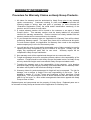
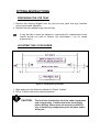
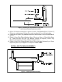
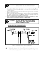
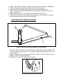
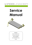
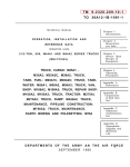
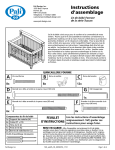
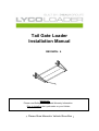
Tail Gate Loader Installation Manual REVISION: 4 IMPORTANT Please read Safety Warnings and Warranty Information Prior to Installing the LycoLoader on your Vehicle Please Store Manual in Vehicle Glove Box _____________________________________ TABLE OF CONTENTS _____________________________________ REVISION: 4 ......................................................................................................................................................................................... 1 IMPORTANT ............................................................................................................................................................. 1 GENERAL SAFETY WARNINGS REGARDING FITMENT ......................................................................3 GENERAL SAFETY WARNINGS FOR OPERATION .................................................................................3 PRODUCT WARRANTY. .................................................................................................................................4 WARRANTY INFORMATION ........................................................................................................................5 A NOTE TO OWNERS ......................................................................................................................................6 LYCO PARTS AND SERVICE DIVISION ......................................................................................................6 PARTS LIST ........................................................................................................................................................7 TOOLS REQUIRED FOR INSTALLATION ..................................................................................................7 FITTING INSTRUCTIONS ...............................................................................................................................9 PREPARING THE UTE TRAY ............................................................................................................................9 LOCATING THE LYCOLOADER ......................................................................................................................9 INSTALLING THE TRAY BRACKETS ...........................................................................................................10 INSTALLING THE MAIN ASSEMBLY ...........................................................................................................11 INSTALLING THE TENSION STRAPS ...........................................................................................................12 ATTACHING THE TENSION STRAPS ............................................................................................................13 OPERATION ......................................................................................................................................................14 APPENDIX 1 - LONGITUDINAL UNDER TRAY SUPPORTS.................................................................15 APPENDIX 2 - SIDE CONNECTION ............................................................................................................17 APPENDIX 3 - SIDE ATTACHMENT FOR OTHER TRAY TYPES* .....................................................19 Date of issue 23/04/14 Page 2 GENERAL SAFETY WARNINGS REGARDING FITMENT Do not fit the Lycoloader to damaged or structurally unsound tray bodies (e.g. those with corroded floor and/or structural members or damaged or corroded timber floors) Do not fit the LycoLoader to tray bodies with longitudinal timber floors unless transverse reinforcement is added beneath the floor to spread the load across the floor boards Do not drill above wiring or componentry located directly under the tray body GENERAL SAFETY WARNINGS FOR OPERATION Do not operate with unstable loads Do not operate with live loads Do not operate on uneven ground Keep hands and feet clear while operating Ensure towbar is clear of platform Remove handle before moving vehicle Stow platform before moving vehicle Only qualified persons should operate mechanism Do not use external power devices to operate mechanism Stop winding the handle when the platform is fully raised Product Warranty. Lyco Innovations warrant to the owner of each new product sold that for the specified period commencing from the date of purchase, that at its discretion, Lyco will repair or replace, free of charge, any product or component found to be defective in materials and/or workmanship. The standard product warranty period is for 12 months or 1040 hours of operation, whichever occurs first. Warranty periods different to this are specified on Lyco Innovations sales brochures. This warranty shall exclude defects occurring through incorrect or inappropriate: storage, transport, non Lyco design, application, use, or, accident, or, wilful damage, or as a result of unauthorised or incompetent servicing by other than Lyco staff or authorised persons. Notwithstanding any statutory obligations under certain legislation, including the Trade Practices Act prevailing in the state or territory the product was sold, Lyco accepts no liability for any consequential loss or damage due to product failure or late delivery, and limits any liability that it might nevertheless have to a maximum amount being the invoiced price of the product. To ensure ongoing warranty cover subsequent owners must notify Healy Group in writing stating: the product, the serial number and the date of purchase. Philip Healy Managing Director Healy Group P/L 4/12 Northumberland Rd Caringbah NSW 2229 Ph: 02 95255522 Fax: 02 92525513 www.healygroup.com.au/lyco-loader [email protected] WARRANTY INFORMATION Procedure for Warranty Claims on Healy Group Products. 1. All claims for warranty must be authorised by Healy Group prior to any warranty repairs commencing. Customers wanting to claim warranty must provide the following details in writing: date and proof of purchase (or have returned the “Guarantee Registration Card”) the serial and/or identification number(s) of the product, and, the reason for such claim. 2. A unique warranty number will be issued to the customer or an agent of Healy Groups choice. This warranty number must be clearly labelled on all product returned for warranty assessment. Product received not clearly labelled with the warranty number will be returned direct to the sender. 3. If Lyco accepts the warranty claim, an “Application for Warranty” form will be raised, authorising warranty repairs. The repair time frame will be confirmed at this point. For sub contract repairs, the Application for Warranty form needs to be completed and accompany any invoice for the warranty claim. 4. Lyco will pay the cost of parts and/or reasonable costs of labour actually incurred in repairing the faulty component(s) by the customer or an agent. Usually Lyco will supply any replacement parts from its own stock. Warranty repairs will be completed to Healy Groups satisfaction. 5. Non-warranty work will be repaired and charged out at commercial rates. 6. Freight and postage incurred to complete warranty claims is the responsibility of the customer. Freight should be with Healy Groups nominated carrier, as Healy Group will only reimburse freight costs incurred with Healy Groups nominated carrier. 7. Travelling for warranty work is the responsibility of the customer. In its absolute discretion Healy Group may pay travelling costs associated with the warranty claim. No labour will be paid for the time that travelling is claimed. 8. Warranty claims for products damaged in freight will not be accepted. The risk for damage, loss or delays in freight is the sole responsibility of the buyer. This is detailed in section 5.1 of the “Terms and Conditions of Sale” document (Credit Application). The only exception to this is where insurance has been taken out and paid for by the buyer, or, other written arrangements have been agreed with Healy Group at time of order. Replaced parts and components are the property of Healy Group. Replaced parts are to be returned to Healy Group as directed on the Application for Warranty form. A NOTE TO OWNERS Please take time to fill in the warranty card and return it to Healy Group P/L At the address shown on the front of card. Healy Group Parts & Service Division If any parts are missing (see Parts List on Page 7) from the LycoLoader Package please contact Healy Group. Note: Delivery of the parts will be arranged using express post. If the LycoLoader is not operating (see Operation on Page 13) correctly for any reason contact Healy Group: Healy Group P/L 4/12 Northumberland Rd Caringbah NSW 2229 02 9525 5522 Fax 02 9525 5513 Email: [email protected] PARTS LIST The LycoLoader Package should contain: ITEM* DESCRIPTION 1 2 3 4 5 6 7 8 9 10 11 12 13 14 15 16 17 18 19 General Assembly Tray Bracket - Right Hand Tray Bracket - Left Hand Tension Straps Under Tray Supports (angle reinforcements) Mounting Plate (side spacer plates) Clasp Handle Bolt – 12mm x 75mm Long Bolt - 12mm x 65mm Long Coach Bolt Bolt - 10mm x 50mm Long Bolt - 8mm x 25mm Long Washer – 12mm Flat Zinc Plated Washer - 10mm Flat Zinc Plated Washer - 8mm Flat Zinc Plated Washer - 8mm Spring Zinc Plated Nut - 12mm Nyloc Nut - 10mm Nyloc Spacers QTY 1 1 1 2 2 2 2 1 4 2 2 4 10 4 4 4 6 2 6 Table 1 - Parts List * Refer to Figure 1 on Page 6 for further details. Please note that a Side Attachment Kit or some other arrangement may be required for attachment between the LycoLoader uprights and the tray body’s original drop sides. The Side Attachment Kit is NOT INCLUDED in the standard LycoLoader Fitting Kit but can be bought separately from your local dealer or Lyco Parts and Service. Please quote Part No. –LLSideAttach. TOOLS REQUIRED FOR INSTALLATION The following tools are required for installing you LycoLoader onto your vehicle: Hammer Electric Drill Centre Punch Tape Measure / Ruler 12.5mm (or 1/2”) Drill Bit Socket Set including 19mm, 18mm, 16mm, 14mm, 13mm Sockets Ring Spanner Set including 19mm, 18mm, 16mm, 14mm Spanners Figure 1 - LycoLoader Assembly Drawing FITTING INSTRUCTIONS PREPARING THE UTE TRAY 1. Remove the existing tailgate from the tray and any parts that may interfere during LycoLoader operation. 2. Remove the rear tailgate hinge from the tray. It may be wise to store the tailgate in a safe place for reattachment to the vehicle should you wish to remove the LycoLoader ( e.g. for resale purposes etc. ) LOCATING THE LYCOLOADER Figure 2 - Locating the LycoLoader 1. Mark and punch the holes as indicated in Figure 2 above. 2. Drill a 12.5mm hole at the marked positions CAUTION - The bolt hole should clear all of the under tray braces and componentry. Position the holes accordingly before drilling. Also ensure the area to be drilled is free of under tray componentry such as lights and/or wiring etc. Figure 3 - Bolt Clearance INSTALLING THE TRAY BRACKETS The tray brackets must sit flat on the tray. If the tray has a combing rail around the edge of it, a suitable spacer plate must be used. See Figure 4 below for further details. Figure 4 - Using a Spacer Plate LIGHT TRAYS - For light trays (e.g. aluminium, timber, or light gauge steel), extra support in the form of under tray reinforcement needs to be added to ensure the load is spread across the tray. For suggestions on tray supports see Appendix 1. NOTE: ALTERNATIVE CONFIGURATIONS MAY NEED TO BE DETERMINED FOR SOME TRAY TYPES. Figure 5 - Installing the Tray Bracket on Trays that DON’T Require Additional Reinforcement 1. Drill a 12.5mm hole along the v-groove in each Tray Bracket [Item 2 & Item 3] 75mm (or as determined to clear the under tray braces) from the back edge. 2. Place the Left Hand Tray Bracket above the drilled holes on the left hand side of the ute. 3. Place a 12mm Zinc Plated Washer [Item 13] onto a 12mm x 75mm Bolts [Item 9]. Insert the Bolt thru the Tray Bracket, Spacer (if required), Under Tray Support (if required), and Tray. Repeat for both holes. 4. Place a 12mm Zinc Plated Washer [Item 13] on each bolt followed by a 12mm Nyloc Nut [Item 15] and tighten to a torque of 25 to 30 Nm. INSTALLING THE MAIN ASSEMBLY Figure 6 - Installing the Main Assembly CAUTION - DO NOT LIFT THE PLATFORM ALONE OR WITHOUT THE AID OF A LIFTING DEVICE 1. Lift the Main Platform [Item 1] and insert into the Left Hand Tray Bracket (NOTE: THIS SHOULD NOT BE DONE ALONE OR WITHOUT THE AID OF LIFTING DEVICE). 2. Place the Right Hand Tray Bracket [Item 2] onto the right hand side of the Main Platform and position on tray. 3. Place a 12mm Zinc Plated Washer [Item 13] onto a 12mm x 75mm Bolts [Item 9]. Insert the Bolt thru the Tray Bracket, Spacer (if required), Under Tray Support (if required), and Tray. Repeat for both holes. 4. Place a 12mmZinc Plated Washer [Item 13] on each bolt followed by a 12mm Nyloc Nut [Item 15] and tighten to a torque of 25 to 30 Nm. CAUTION - THE TRAY BRACKETS MUST BE SECURELY FIXED TO THE TRAY. THE LOAD SHOULD BE SPREAD ACROSS THE TRAY INSTALLING THE TENSION STRAPS Figure 7 - Installing the Tension Straps - Left Hand Side Tighten the nyloc nut firm while still allowing the tension strap to move freely. Repeat this for both tension straps, ensuring that the straps are on the inside of each tray brackets. 1. 2. 3. 4. Insert a 10 x 50mm bolt [Item 11] thru the short arm of the tension strap [Item 4]. Place a 10mm zinc plated washer [Item 14] on the 10mm bolt. Insert the bolt thru the top hole in the left hand tray bracket [Item 2]. Place a 10mm zinc plated washer [Item 14] on the bolt, followed by a 10mm nyloc nut [Item 16]. 5. Tighten the nyloc nut, ensuring the tension strap is free to rotate. 6. Repeat the procedure on the right hand tray bracket, ensuring that the tension strap is placed on the inside of the tray bracket. ATTACHING THE TENSION STRAPS Figure 8 - Raising the Platform to Attach the Tension Straps 1. Lift the LycoLoader platform by the T-Section, supporting it until the angle of the slot in the tension strap long arm matches the angle of the platform T-Bolt, see Figure 8 above. 2. Whilst maintaining the angle of the platform, slip the Tension Strap over the platform T-Bolt, see Figure 9 below. 3. Repeat the procedure for both Tension Straps. Figure 9 - Attaching the Tension Straps OPERATION Check the operation of the unit after it is fitted: Ensure all 12mm bolts are tightened securely to a torque of 25 to 30 Nm. Test the LycoLoader with the Platform unloaded. Refer to “Operating Manual” for full operating procedures and safety precautions prior to loading and unloading the LycoLoader (including any test loads). 1. Insert the Handle [Item 8] into the left hand side of the platform assembly until its triangular end engages the triangular recess of the winding mechanism (inside the box section). 2. Turn the Handle Anti-clockwise to lower the platform. 3. Release the handle when the platform is half way down. The platform should remain in this position. 4. Wind the platform fully down and then back up to ensure there is no interference with any part of the vehicle. 5. Repeat the test with a load of approximately 50kg to ensure the LycoLoader is functioning correctly. 6. Once the test is satisfactorily completed, secure the platform in its hinged upright position and ensure the retaining catches on the tray brackets are fully fastened. 7. Store the LycoLoader handle in a secure position in the cab of the vehicle where it is not likely to dislodge and cause injury to vehicle occupants in an accident or crash-stop situation. A suitable location would be on the floor behind the driver’s or passenger’s seat. If the LycoLoader is not operating correctly for any reason contact Healy Group P/L parts and service on : 02 9525 5522 Fax 02 9525 5513 Email: [email protected] APPENDIX 1 - LONGITUDINAL UNDER TRAY SUPPORTS Figure 10 - Under Tray Supports - Left Hand Side IT IS IMPORTANT TO ENSURE THE LYCOLOADER IS SECURELY FIXED TO THE TRAY WITH THE LOAD SPREAD EVENLY. LONGITUDINAL UNDER TRAY SUPPORTS MUST NOT BE USED ON TRAY BODIES WITH LONGITUDINAL WOODEN OR ALUMINIUM FLOORS. UNDER TRAY SUPPORTS MUST BE MOUNTED PERPENDICULAR TO THE DIRECTION OF ANY JOINTS IN THE FLOOR. 1. Mark and Drill holes for coach bolts in both the tray and support, 12.5 hole. The Coach Bolts should be placed approximately 50mm from the end (opposite end to the existing slots) of the Under Tray Support, ensuring the holes clear the under tray braces. 2. Insert the 12mm Coach Bolts thru the drilled holes on both sides*. 3. Place the Spacers [Item 19] under the tray on the 12mm Coach Bolts. 4. Place the Under Tray Supports under the tray, onto the 12mm Coach Bolts. 5. Place a 12mm Washer onto the Coach Bolt, followed by a 12mm Nyloc Nut and tighten to a torque of 25 to 30 Nm. 6. Drill a 12.5mm hole along the v-groove in each Tray Bracket [Item 2 & Item 3] 75mm (or as determined to clear the under tray braces, see Figure 3) from the back edge of the tray bracket. 7. Place the Left Hand Tray Bracket above the drilled holes on the left hand side of the ute. 8. Place 12mm Zinc Plated Washer [Item 13] onto a 12mm x 75mm Bolts [Item 9]. Insert the Bolt thru the Tray Bracket and Tray. Repeat for both holes. 9. Place the Spacers [Item 19] under the tray on the 12mm x 75mm Bolts. 10. Place 12mm Zinc Plated Washer [Item 13] on each bolt followed by a 12mm Nyloc Nut [Item 15] and tighten to a torque of 25 to 30 Nm. * Note: It may be necessary to file the holes square to ensure the coach bolts sit flat against the floor of the tray body. Ensure that the Spacers [Item 19] and Under Tray Support [Item 5] are installed on the Right Hand Side as well prior to tightening the bolts and nuts. Refer to “Installing the Main Assembly” to complete the installation of the LycoLoader. APPENDIX 2 - SIDE CONNECTION The LycoLoader comes with 2 adjustable side-mounting plates for attachment between the LycoLoader Tray Brackets and the tray body’s existing dropsides. These plates are suitable for tray widths between 1803mm (71”) and 1854mm (73”) For tray bodies outside this range, a side attachment arrangement may need to be devised. An optional fitting kit (the LycoLoader Side Attachment Kit) is available to suit wider trays between 1854mm (73”) and 1905mm (75”). It is available from your local dealer or Lyco Parts and Service. For more information on side connections for other tray types, please refer to Appendix 3. Figure 11 outlines the set-up for installing the side connection plates, that are included in the standard fitting kit supplied with each LycoLoader. Please note that the following items are removed from the tray body’s tailgate and tray sides and reused in the side connection. Item Description Location A Tailgate plate Rear Tailgate - Outer Edge B Side pivot handle Dropside C Tray side angle Dropside D Handle retainer Dropside Table 2 - Re-used Parts from Tray 1. Remove Items A, B, C & D from the tailgate and tray side 2. Attach Item A to the tray side using the same bolts that were used to hold it to the tailgate, making sure the raised latch stop is on the outside of the plate. 3. Place a bolt (one that was used to attach Item B to the tray side) thru Item 7, thru Item B, and finally thru Item 6. Also fasten the bottom of Item B to Item 6. 4. Slide Item D into Item 7. 5. Insert Item C into Item B & D. Fasten with spring washer and nyloc nut (previously removed). 6. Attach Item 6 to Item 2/3 with the Item 12 (Bolt - 8mm x 25mm Long). 7. Repeat for both sides. Figure 11 - Side Attachment example APPENDIX 3 - SIDE ATTACHMENT FOR OTHER TRAY TYPES* * Required for trays with dropsides If both the Standard Kit and Side Attachment Kit cannot be fitted to the tray, an alternative side attachment will have to be developed and fitted for two reasons. 1. To fill the gap between the outer edge of the LycoLoader Tray Bracket and the tray body’s existing dropside, and 2. To provide a method for securing the end of the tray body’s dropsides to the end of the tray. Figure 12 - Fabricated Attachment for to Secure Dropsides This can be done by fabricating a side attachment plate to suit the tray body concerned and then adding a suitable bracket to engage and retain the existing latch on the end of the tray body’s dropside. If the existing tray body’s latch cannot be adopted for use with the side attachment plate, the existing latch may need to be removed and discarded and replaced with a new latch arrangement such as the one supplied in the Side Attachment Kit, part no. LL-Side Attach.