1
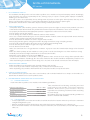
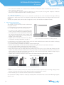
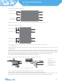
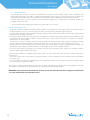
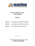
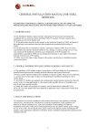
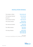
INSTALLATION MANUAL
IEC VERSION
TSM_IEC_IM_2011_RevA
INSTALLATION MANUAL
IEC version
1. DISCLAIMER OF LIABILITY
The installation, handling and use of Trina Solar Crystalline series modules are beyond company control. Accordingly,
Trina Solar does not assume responsibility for loss, damage, injury or expense resulting from improper installation,
handling, use or maintenance.
Trina Solar assumes no responsibility for any infringement of patents or other rights of third parties that may result
from use of the module. No license is granted by implication or under any patent or patent rights.
Specifications included in this manual are subject to change without prior notice.
2. SAFETY PRECAUTIONS
• Solar photovoltaic (SPV) modules generate electricity when exposed to light. An array of many modules can cause
lethal shocks and/or burn hazards. Only authorized and trained personnel should have access to the modules.
• Use properly insulated tools and appropriate protective equipment to reduce risk of electric shock.
• Do not stand or step on the module.
• Do not damage or scratch the front or backside surfaces of the module.
• Never use a module with broken glass or torn substrate. Broken modules cannot be repaired and contact with any
module surface or frame can lead to electrical shock.
• Do not disassemble the modules or remove any part of the module.
• Protect plug contacts against soiling; do not make any plug connections using soiled plug contacts.
• Do not install or handle modules when they are wet or during periods of high wind.
• Do not short the positive and the negative of a single SPV module.
• Do not disconnect under load.
• Make sure connectors have no gap between insulators. A gap can cause fire hazard and/or danger of an electrical
shock.
• Make sure that the polarity of each module or a string is not reversed considering the rest of the modules or strings
• Artificially concentrated sunlight should not be used on the SPV module.
• Maximum system voltage must not exceed 1000V DC.
• Under normal conditions, a SPV module is likely to produce more current and /or voltage than reported under
standard test conditions. Accordingly, the value of Isc marked on this module should be multiplied by a factor of 1.25
when determining the conductor current ratings, fuse sizes and size of controls connected to the SPV output.
3. UNPACKING AND STORAGE
• Before installation, keep all modules and electrical contacts clean and dry.
• If it is necessary to store modules temporarily, a dry, ventilated room should be used.
• When unpacking, carry modules with both hands. Do not place modules on top of each other.
4. PRODUCT IDENTIFICATION
We recommend that you take note of the serial number, each individual module has a unique serial number. It is
attached to the backsheet next to the product sticker.
5. ENVIRONMENTAL CONDITIONS AND SITE SELECTION
5.1 CLIMATE CONDITION
Install Trina Solar Crystalline series modules in the following conditions:
Ambient Temperature:
-40°C to +40°C
Operating Temperature:
-40°C to +85°C
Storage Temperature:
-20°C to +40°C
Humidity:
below 85RH%
Mechanical Load Pressure: below 112.78lb / ft2 (5400Pa)*
*
Note: Mechanical load bearing (including wind and
snow loads) of each module is based on mounting
methods. Professional system installers must be
responsible for calculating mechanical loads according
to system design.
The modules have been designed according to IEC61215
edition 2 and IEC61730 standards.
5.2 SITE SELECTION
• In most applications, Trina Solar SPV modules should be installed in a location where they will receive maximum
sunlight throughout the year.
• Modules should be free from shaded at any time of the day because of buildings, trees, chimney, etc.
• Do not install SPV modules in environments subject to corrosion, such as costal areas, or areas with high levels of
sulfur, etc.
2
INSTALLATION MANUAL
IEC version
• Do not install SPV modules in a location where it would be immersed in water or continually exposed to water
from a sprinkler or fountain, etc.
• For roof installations, modules should be mounted over a fire resistant covering, with adequate ventilation
between the module backsheet and the mounting surface.
5.3 MODULE TILT ANGLE
Trina Solar SPV modules connected in series should be installed at the same orientation and angle. Differing
orientations or angles may cause a loss of power output due to differing amounts of sunlight exposure for each
module.
Typically, the optimal tilt for a SPV module is roughly the same as the latitude of installation location.
6. MOUNTING INSTRUCTIONS
6.1 MOUNTING METHODS
SPV modules can be mounted to the substructure
using two methods:
(1) Screw fitting: Using corrosion-proof screws (M8) in
the existing installing holes in the module frame.
• The frame of each module has 4 mounting holes
used to secure the modules to supporting structure.
• The module frame must be attached to a mounting
rail using M8 corrosion-proof screws together with
spring washers and flat washers in four symmetrical
locations on the SPV module.
• Applied torque should be 8 Newton-meters. Please
find detailed mounting information in Figure 1.
Figure1. SPV module installed with screw fitting method*
(2) Clamp fitting: Using suitable module clamps on the side of the module frame to mount the modules (including
“portrait orientation” and “landscape orientation”)
• Use a certain number of clamps to fix modules on the mounting rail.
• Modules clamps should not come into contact with the front glass and must not deform the frame.
• Be sure to avoid shadowing effects from the module clamps.
• The module frame is not to be modified under any circumstances.
• When choosing this type of clamp-mounting method, please be sure to use at least four clamps on each
module, two clamps should be attached on the long sides of the module (for portrait orientation) and short sides
of the module (for landscape orientation). Depending on local wind and snow loads, additional clamps may be
required to ensure modules can bear the load.
• Applied torque should be 8 Newton-meters. Please find detailed mounting information in Figure 2.
Fringe modules installation
Middle modules installation
Figure2. SPV module installed with clamp fitting method*
* Note:
• Clearance between modules frames and surface of the wall or roof is required to prevent wiring damage and to
allow air to circulate behind the module. Recommended stand-off height is 115mm.
• When mounting, be sure that the module's drain holes are not blocked.
We recommend installing modules in landscape and/or portrait orientation. Please refer to the following diagrams
(Figure 3 & 4 ).
3
INSTALLATION MANUAL
IEC version
(1) Landscape orientation installation
1/20 Module Width
1/5 Module Width
Mounting
Area
1/5 Module Width
Mounting
Area
1/20 Module Width
Figure3. Mechanical dimensions when modules installed in landscape orientation with clamp fitting method
(2) Portrait orientation installation
1/8 Module Length
Mounting
Area
1/4 Module Length
1/4 Module Length
Mounting
Area
1/8 Module Length
Figure4. Mechanical dimensions when modules installed in portrait orientation with clamp fitting method
6.2 GROUNDING
• All module frames and mounting racks must be properly grounded in accordance with respective national
electrical code.
• Proper grounding is achieved by bonding the module frame(s) and all metallic structural members together
continuously using a suitable grounding conductor. The grounding conductor or strap may be copper, copper
alloy, or other material acceptable for use as an electrical conductor per respective National Electrical Codes. The
grounding conductor must then make a connection to earth using a suitable earth ground electrode.
• We recommending using the following methods to ground properly:
Method 1: The Ilsco GBL-4DBT Lay-in lug as shown in the following picture:
1
2
3
5
4
6
7
8
1) #8 screw
2) Nut
3) Tooth washer
4)A luminiu m fram e
5) Stainless steel washer
6)La y-inl ug
7) 4-12 AWG cable
8) Stainless steel screw
Figure5. Ilsco GBL-4DBT Lay-in lug
• Secure a grounding lug (e.g. tin-plated copper) with a stainless steel bolt and nut.
• Insert a stainless steel washer (e.g. flat, locking) between the grounding lug and frame.
• Make electrical contact by penetrating the anodized coating of the aluminium frame, usually a stainless steel
toothed washer can be inserted between the nut and the frame to break the anodized layer of frame.
4
INSTALLATION MANUAL
IEC version
6.3 MODULE WIRING
Each module has two 4mm2 diameter standard 90°C sunlight resistant output cables each terminated with
plug & play connectors. This cable is suitable for applications where wiring is exposed to the direct sunlight. We
recommend that all wiring and electrical connections comply with the appropriate national electrical code.
For field connections, use the minimum 4mm2 diameter copper wires insulated for a minimum of 90°C and
Sunlight resistance as well.
• The minimum and maximum outer diameters of the cable are 5 to 7mm2.
7. MAINTENANCE AND CARE
• Under most weather conditions, normal rainfall is sufficient to keep the PV module glass surface clean. If dust or dirt
build-up becomes excessive, clean the glass only with a soft cloth using mild detergent and water.
• Do not clean the modules with cold water during the warmer hours of the day in order to avoid creating any thermal
shock that may damage the module.
• Be cautious when cleaning the back surface of the module to avoid penetrating the substrate material. Modules that
are mounted flat (0° tilt angle) should be cleaned more often, as they will not ''self clean'' as effectively as modules
mounted at a 15° tilt or greater.
• At least once a year, it is recommended to check the torque of terminal screws and the general condition of wiring.
Also, check that mounting hardware is properly torqued. Loose connections will result in damage to the array.
• Modules that have been replaced must be of the same type. Do not touch live parts of cables and connectors. Use
appropriate safety equipment (insulated tools, insulating gloves, etc.) when handling modules.
• Cover the front surface of modules by an opaque material when repairing. When exposed to sunlight, modules
generate high voltage and thus dangerous.
Trina Solar SPV modules are equipped with bypass diodes in the junction box. This minimizes module heating and
current losses.
• Do not try to open the junction box to change the diodes even if it malfunctions. This should be done by qualified
personnel only.
• In a system that uses a battery, blocking diodes are typically placed between the battery and the SPV module output
to prevent battery discharge at night.
Trina Solar is a member of the European PV Cycle Association. Through the pre-financed PV Cycle program, Trina Solar
SPV modules will be taken back and treated in an environmentally sustainable manner.
WARNING: For any electrical maintenance, the SPV system must first be shut down. Improper maintenance
can cause lethal electric shock and/or burns.
5