1
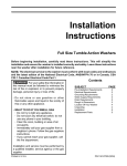
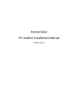
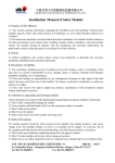
Worldwide Energy and Manufacturing USA, Co., LIMITED
Add: RM 1708 C1, NAN FUNG TOWER,
173 DES VOEUX RD CENTRAL, HK
Installation Manual
Worldwide Energy and Manufacturing USA, Co., LIMITED
Add: RM 1708 C1, NAN FUNG TOWER,
173 DES VOEUX RD CENTRAL, HK
Content
1. General information.................................................................................... 1
2. Safety precautions...................................................................................... 1
3. Storage and unpacking .............................................................................. 1
4. Product identification................................................................................. 2
5. Mechanical installation .............................................................................. 2
5.1 Climate condition ................................................................................ 2
5.2 Site selection ....................................................................................... 2
5.3 Module tilt angle .................................................................................. 3
5.4 Installation methods............................................................................ 3
6. Electrical installation.................................................................................. 5
6.1 Module wiring ...................................................................................... 5
6.2 Grouding .............................................................................................. 5
7. Maintenance................................................................................................ 6
8. Disclaimer of liability.................................................................................. 6
Worldwide Energy and Manufacturing USA, Co., LIMITED
Add: RM 1708 C1, NAN FUNG TOWER,
173 DES VOEUX RD CENTRAL, HK
1. General information
This manual contains information regarding the installation and safe handling of Amerisolar
photovoltaic modules. Installers should read this manual carefully and follow the instructions
strictly prior to installing the modules. Failure to follow these instructions may result in death,
bodily injury or damage to property.
The installation of modules requires specialized skills and should only be performed by
qualified, licensed professionals. If you have any questions about installation, please contact
us for further information.
2. Safety precautions
l
Amerisolar modules have passed all required safety tests according to the IEC 61730 and
are rated with Application Class A, and within this application class modules are considered
to meet the requirements for Safety Class II.
l
All installations must be performed in compliance with all local and national applicable
standards, codes and regulations.
l
Installers should assume all risks of injury that might occur during installation, including,
but not limited to, the risk of electric shock.
l
Do not use mirrors or other magnifiers to artificially concentrate sunlight on the modules.
l
Do not attempt to disassemble the modules or remove any components from the modules.
l
Do not install the module in the rain, snow or in windy conditions.
l
Use electrical insulated tools and appropriate protective equipment to reduce risk of
electric shock.
l
Cover the module with an opaque material during installation to keep electricity from being
generated.
l
Do not disconnect under load.
3. Storage and unpacking
l
Store modules in a dry and ventilated room.
l
Unpack module pallets with care and follow the unpacking steps. Be careful when
unpacking, transporting, and storing the modules.
l
Do not lift the module by grasping the module’s junction box or electrical leads.
l
Do not place modules on top of each other.
l
Do not stand or step on the module.
1
Worldwide Energy and Manufacturing USA, Co., LIMITED
Add: RM 1708 C1, NAN FUNG TOWER,
173 DES VOEUX RD CENTRAL, HK
l
Do not drop the module or allow objects to fall on the module.
l
Do not leave the module unsupported or unsecured.
l
Keep all electrical contacts clean and dry.
4. Product identification
Each Amerisolar module has two identical barcodes with 15 digits for its unique identification
(one is in the laminate, and the second is on the backsheet).
A nameplate is affixed on the backside of the module. This nameplate describes main
characteristics of the module, which include the product type, maximum power, open circuit
voltage, short circuit current, maximum power voltage, maximum power current, all as
measured under standard test conditions; maximum system voltage, weight, dimensions etc..
Do not remove any labels from the module. If the label was moved out, the module will void
the warranty.
5. Mechanical installation
5.1 Climate condition
Amerisolar modules should be installed in the following conditions:
l
Ambient temperature:
-20°C to +40°C
l
Operating temperature:
-40°C to +85°C
l
Storage temperature:
-40°C to +40°C
l
Humidity:
below 85RH%
l
Wind load:
below 2400Pa
l
Snow load:
below 5400Pa
5.2 Site selection
Amerisolar modules should be installed in a location where they will receive maximum
sunlight throughout the year. In the northern hemisphere, the module should typically face
south, and in the southern hemisphere, the modules should typically face north.
When choosing a site, avoid trees, buildings or obstructions, which could cast shadows on
the modules especially during the winter months when the arc of the sun is lowest over the
horizon. Shading causes loss of output, even though bypass diodes have been fitted in the
junction box of the module to minimize any such loss.
Do not install the module near naked flame or flammable materials.
Do not install the module in a location where it would be immersed in water or continually
2
Worldwide Energy and Manufacturing USA, Co., LIMITED
Add: RM 1708 C1, NAN FUNG TOWER,
173 DES VOEUX RD CENTRAL, HK
exposed to water from a sprinkler or fountain etc.
5.3 Module tilt angle
Modules connected in series should be installed at same orientation and angle. Different
orientation or angle may cause loss of output power due to difference of amount of sunlight
exposed to the module.
Modules produce the most power when they are pointed directly at the sun. For installations
where the modules are attached to a permanent structure, the modules should be tilted for
optimum winter performance. As a rule, if the system power production is adequate in winter,
it will be satisfactory during the rest of the year. Optimal tilting of the module is roughly the
same as the latitude of installation location.
5.4 Installation methods
The modules can be installed on the frame using screw mounting and clamp mounting
methods (as shown in Fig.1).
(a) Screw mounting
(b) Clamp mounting
Fig.1 The module installed with (a) screw mounting, (b) clamp mounting
(a) Screw mounting
The frame of each module has eight mounting holes used to secure the modules to the
support structure. If the wind or snow loads is less than 2400Pa, you can use the four
symmetry holes close to the inner side on module frame(as shown in Fig.2). If the wind or
snow load exceeds 2400Pa, you must use all the eight mounting holes. The module frame
must be attached to a mounting rail using M8 corrosion-proof screws together with spring
washers and flat washers in eight symmetrical locations on the module.
3
Worldwide Energy and Manufacturing USA, Co., LIMITED
Add: RM 1708 C1, NAN FUNG TOWER,
173 DES VOEUX RD CENTRAL, HK
Fig.2 The module installed on long frames with screw mounting method
(b) Clamp mounting
l
The modules can be installed in both landscape(clamping on the short frame) and portrait
(clamping on the long frame) modes by clamp mounting.
l
The module clamps should not come into contact with the front glass and must not deform
the frame.
l
Be sure to avoid shadowing effects from the module clamps.
l
The module frame is not to be modified under any circumstances.
l
When choosing this type of clamp mounting method, please be sure to use at least four
clamps on each module, two clamps should be attached on each frame of the module.
Depending on the local wind and snow loads, if the pressure load exceeds 2400Pa,
additional clamps or support would be required to ensure the module can bear the load.
For clamping mounting on the long or short frame of the module, please refer to Fig.3 and
Fig.4.
200m m
1 /4 le n g th
L e n g th
Fig.3 The module installed on long frames with clamp mounting method
4
Worldwide Energy and Manufacturing USA, Co., LIMITED
1/4 width
100mm
Add: RM 1708 C1, NAN FUNG TOWER,
173 DES VOEUX RD CENTRAL, HK
Fig.4 The module installed on short frames with clamp mounting method
6. Electrical installation
6.1 Module wiring
Modules are supplied with cables and connectors to be used for system electrical
connections. It is not recommended to use modules with different configurations and
electrical characteristics in the same system.
Modules can be connected in series to obtain a high operating voltage. The system voltage is
equal to the sum of the voltage of each module. Modules can also be connected in parallel to
obtain a high operating currents. The system current is equal to the sum of the current of
each string of modules.
The maximum number of series connected modules depends on system design, the type of
inverter used and environmental conditions. It should be noted that modules must not be
connected together to create a voltage higher than the permitted system voltage. There is no
limitation on the number of modules that can be connected in parallel, the number of modules
is determined by system design parameters such as current or power output.
6.2 Grouding
Grouding modules is necessary to reduce or eliminate shock and fire hazards. All module
frames and mounting racks must be properly grounded in accordance with local and national
electrical codes. Proper grounding is achieved by connecting the module frames and
mounting racks continuously using a suitable grounding conductor. The grounding conductor
or strap may be copper, copper alloy, or other material acceptable for use as an electrical
conductor.
5
Worldwide Energy and Manufacturing USA, Co., LIMITED
Add: RM 1708 C1, NAN FUNG TOWER,
173 DES VOEUX RD CENTRAL, HK
7. Maintenance
The following maintenance measures are recommended to ensure optimum performance of
the modules:
l
Under most weather conditions, normal rainfall is sufficient to keep the glass surface of
modules clean. Clean the glass surface of the module as necessary.
l
Always use clean water and a soft sponge or cloth for cleaning.
l
If snow accumulates on top of the modules, remove the excess snow gently from the
surface of the modules using a brush or broom.
l
Check the electrical and mechanical connections periodically to make sure that all
connections are tight, secure, intact and free of corrosion.
l
Do not try to change the components of module (Junction box, bypass diode and
connector).
l
If any problem arises, consult a professional for suggestions.
8. Disclaimer of liability
Because the use of this manual and the conditions or methods of installation, operation, use
and maintenance of the product are beyond Amerisolar’s control, Amerisolar does not accept
responsibility and expressly disclaims liability for loss, damage, or expense arising out of or in
any way connected with such installation, operation, use or maintenance.
No responsibility is assumed by Amerisolar for any infringement of patents or other rights of
third parties, which may result from use of the product. No license is granted by implication or
otherwise under any patent or patent rights.
The information included in this manual is based on Amerisolar’s knowledge and experience
and is believed to be reliable; but such information including product specification (without
limitations) and suggestions do not constitute a warranty, expresses or implied. Amerisolar
reserves the right to change the manual.
6