1
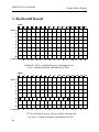
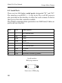
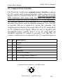
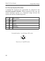
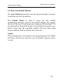
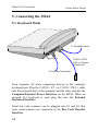
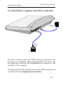
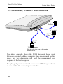
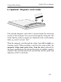
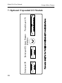
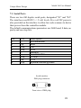
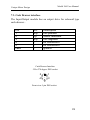
Unique Micro Design
Model M264
Custom Keyboard
User Manual
Document Reference : DOC-M264-UM
UMD Part Number : 6-0264-993-7
Issue : 4
Date : 27/08/01
First Choice of
professional systems integrators
Revision History
Date
05/05/95
19/05/95
Issue
1
2
24/05/96
3
27/08/01
4
Comments
First Issue
Parallel Port change
S3 and S4 reversed page 18
Company Position statement changed
ProtoLink Programming Utility added
Email address added
Change mission statement and setup for
FPD455
Unique Micro Design
Model 264 User Manual
1. Introduction
This manual provides basic information about the Unique Micro
Design Model 264 Custom Keyboard.
The Model 264 is based on the UMD ProtoLink Architecture
which is also used in other products such as wall mount
terminals, multi-in/out wedges, peripheral controllers and custom
VGA terminals.
In essence, the UMD ProtoLink Architecture is a versatile
product development platform which provides the system
integrator with opportunities to ‘add value’.
The architecture specifies the following:
• standard definitions for configuration parameters that can be
consistently used across the entire ProtoLink family of
products.
• standard command set and peripheral control philosophy.
• standard set of hardware facilities which includes non-volatile
memory to hold configuration parameters, serial ports which
provide power for scanners and bar code wand, display,
external keyboard, keyboard wedge and magnetic card reader
interfaces.
• peripheral interface bus that allows the addition of other
modules to the core controller.
The UMD ProtoLink platform has extensive programmable
capabilities, which are not discussed in this manual (contact
Technical Support at Unique Micro Design for further
information).
3
Model 264 User Manual
Unique Micro Design
2. Custom Keyboard Features
The UMD Custom Keyboard Family can have up to 128 keys
arranged in an 8 x 16 matrix. Each key is programmable to return
user defined codes by downloading a text file via the keyboard or
serial port with details being permanently saved. There are no
configuration switches to be tampered with. The customisable
keycaps and layout provide a visual aid to the operator through
key legend, colour and position cues. Connectors are recessed to
reduce footprint and contact with spilled liquids.
There are two types of keys: keycaps type (Model 264-K Series)
and sealed type (Model 264-S Series). With both types, the 8 x 16
grid spacing is flexible allowing a mixture of QWERTY style (half
space offset keys) with chess board style layouts.
The keycaps type has removable keycaps, allowing the user to
reposition the keycaps within the switch matrix. A selection of
keycaps can be ordered with variations in colour, legends, spacers,
style and size (single, double width and quad (double width/
height)). Double width keys can be readily oriented horizontally or
vertically.
The sealed type has a flexible plastic sheet which covers short
travel mechanical keys, which provide tactile feedback. The
keyboards may be labelled by writing on a paper legend insert
sheet or pre-printing the plastic overlay.
The legend insert sheet and plastic overlay are held in place by
registration studs and a fixing lid which is readily opened to enable
quick changes. The sealed keyboard is suitable for moist areas
such as those found in bars, laboratories and restaurants and can be
quickly wiped down.
4
Unique Micro Design
Model 264 User Manual
Products in the UMD Custom Keyboard range have two major
modes of operation - keyboard and serial. In keyboard mode
personal computers connect via the keyboard interface. External
standard keyboards may also be used in series. There are two
serial ports on the keyboard available to attach devices such as
bar code scanners to the PC without the need to alter software.
When used in the keyboard wedge mode Custom Keyboards are
totally transparent to the PC which accepts the keyboard, bar
code, magnetic card and serial inputs as if they were typed from
the standard keyboard. With the serial mode of operation, a plug
pack provides power to the unit. Any key depression, bar code or
magnetic card data read is output on a serial port. The second
serial port is available for auxiliary I/O, eg with a printer or bar
code scanner.
From the factory, the keys in the keyboard are programmed with
their row / column grid position, that is, the key at the top left
corner, when pushed outputs the string “A1”, the next key down
outputs “A2” and so on. There are sixteen LED indicators above
the keypad area. The last LED on the right ( LED 16 ) indicates
the power status. LED 15 is the good read indicator used by the
BCR and optional MCR inputs.
In keyboard mode, LED 12 is programmed to represent the state
of the Numlock, LED 13 Capslock and LED 14 Scroll lock. All
16 LED’s are programmable.
Other options available from UMD to interface to the M264
include: low cost bar code wands, a variety of bar code scanners,
integrated magnetic card reader, expanded I/O (2 serial 1 parallel
ports), keylock or "Touch Memory" security. Unique Micro
Design can also provide a customisation service to meet
specialised requirements.
5
Model 264 User Manual
Unique Micro Design
3. Keyboard layout
LEDS
2
1
3
4
5
6
7
8
9
10
E
F
G
H
I
J
11
12
13
14
15
16
Row 1
2
3
4
5
6
7
8
Column A
B
C
D
K
L
M
N
O
P
Standard 128 key keyboard layout, showing the key
row / column locations and indicator LED’s.
LEDS
2
1
3
4
5
6
7
8
9
10
11
12
13
14
15
16
Row 1
2
3
4
5
6
A6
K6
7
8
Column A
B
C
D
E
F
G
H
I
J
K
L
M
N
127 key keyboard layout, Qwerty offset, showing the
key row / column locations and indicator LED’s.
6
O
P
Unique Micro Design
Model 264 User Manual
3.1. Insert Sheets and Overlays
Legend insert sheets are available for both the keycap and sealed
keyboards. These sheets allow each key to be labelled to suite
the programmed key sequence.
The keycaps type (Model 264-K Series) has removable keycaps,
allowing the user to reposition the keycaps within the switch
matrix. A selection of keycaps can be ordered with variations in
colour, legends, spacers, style and size (single, double width and
quad (double width/height)). Double width keys can be readily
oriented horizontally or vertically.
The sealed type (Model 264-S Series) has a flexible plastic sheet
which covers short travel mechanical keys, which provide tactile
feedback. The keyboards may be labelled by writing on a paper
legend insert sheet or pre-printing the plastic overlay, these are
held in place by registration studs and a fixing lid which is
readily opened to enable quick changes.
7
8
Serial port S1
Reset button
Bar Code Decoder
Interface
External
Keyboard
Interface
Computer
/External
Power Interface
Default button
Serial port S2
Model 264 User Manual
Unique Micro Design
4. Connector Detail for M264
Model 264 User Manual
Unique Micro Design
4.1. Bar Code Decoder Interface
The bar code decoder interface provides connectivity for
industry standard digital wands, slot readers and devices that
emulate wands.
The decoder interface requires input from devices that convert
optical information into digital pulses, representing bars and
spaces which are decoded by the keyboard hardware.
Pin
1
2
3
4
5
6
7
8
9
I/O
i/p
o/p
o/p
Description
no connection
data input
no connection
+5 volts DC
no connection
no connection
signal ground
shield ground
+5 volts DC
Bar code decoder interface
9 Pin DB9 plug, AMP snap release
1
6
5
9
Front view of DB9 plug
AMP snap release
9
Model 264 User Manual
Unique Micro Design
4.2. Serial Ports
There are two full duplex serial ports, designated "S1" and "S2".
The interfaces use RS232 +/- 9 volt levels. Five volt DC power is
also provided on the interface to allow bar code scanners to derive
their power from the controller module.
The default communications parameters are 9600 baud, 8 data, no
parity and one stop bits.
Pin
I/O
Description
1
2
3
4
i/p
o/p
o/p
no connection
RxD
TxD
DTR
5
6
7
o/p
Ground
no connection
5 Volts
8
9
i/p
o/p
CTS
optional auxiliary power
Serial interface
DB9 plug connector
1
6
5
9
Front view of DB9 plug
10
Model 264 User Manual
Unique Micro Design
4.3. Computer/Power Interface
The ProtoLink Architecture computer/power interface connects
to a PC system unit's keyboard interface. When connected in this
manner, power is derived from the PC. Note that the seven pin
DIN connector will mate with five pin 180 degree DIN
connectors which are used to connect the PC to this interface. If
the controller module is not connected to a PC via the keyboard
interface, then power must be supplied externally. Five volts DC
at typically 300 ma is required to operate the controller. The
computer/power interface can accept either 6V to 9V unregulated,
or 5V regulated power inputs. When the unit is supplied with
unregulated power, usually from a 6 to 9V plug pack, an
internally regulated 5V output is provided. Note that this 5V
output is required to be reconnected to the 5V regulated input on
Pin
1
2
3
I/O
i/o
i/o
-
Description
Clock
Data
Reset
4
5
6
7
i/p
i/p
o/p
Ground
5 Volt DC power
DC unregulated power in
5 Volt DC regulated out
Computer/Power interface 7 pin DIN socket
7
3
5
2
6
1
4
Front view of 7 pin DIN socket
11
Model 264 User Manual
Unique Micro Design
4.4. External Keyboard Interface
A standard PC keyboard can concurrently be connected to the
external keyboard interface. When connected in this way, the
custom keyboard operates as a keyboard wedge between the
system unit and the standard keyboard.
Pin
I/O
Description
1
2
3
4
5
i/o
i/o
o/p
Clock
Data
Reset
Ground
5 Volt DC
Keyboard interface 5 pin 180 degree DIN socket
3
5
2
1
4
Front view of 5 pin DIN socket
12
Unique Micro Design
Model 264 User Manual
4.5. Reset and Default Buttons
The reset button physically resets the microcontroller, forcing it
to perform a power up sequence.
The default button is used to return the non volatile
configuration memory back to the default settings. We suggest
the use of the tip of a ball point pen to depress these buttons. To
use this facility, the default button is held whilst pressing the reset
button. Upon reset the controller module will issue three rapid
beeps to indicate that the defaults have been set.
NOTE:
If any changes have been made to the programming of the Model
264, these will be lost when the reset to defaults sequence above
is used.
13
Model 264 User Manual
Unique Micro Design
5. Connecting the M264
5.1. Keyboard Mode
To External Keyboard
Plug into S1
CA202 or CA226
Cable, to Computer
Keyboard port.
To Serial Bar Code Scanner
Turn computer off when connecting devices to the computer
keyboard port. Plug the CA202 ( AT ) or CA226 ( PS/2 ) cable
into the keyboard port of the computer and the other end into the
Computer/External Power Interface on the M264. When an
external 101 keyboard is used plug this into the External
Keyboard Interface.
Serial bar code scanners can be plugged into S1 and S2. Bar
code wand scanners are connected to the Bar Code Decoder
Interface.
14
Model 264 User Manual
Unique Micro Design
5.2. Serial Mode, Computer Serial Port connection.
Plug Pack
CA211
Cable
To Computer
The above example shows the M264 keyboard connected to the
serial port on a computer. When programmed for this mode, any
key depression will send the programmed key sequence to the
serial port of the computer.
The plug pack provides external power to the M264 keyboard and
is connected to the computer/power interface.
15
Model 264 User Manual
Unique Micro Design
5.3. Serial Mode, Terminal - Host connection
Plug Pack
To Terminal
CA6027
Cable
CA6028
Cable
To Host Computer
*Plug the cable that went to the terminal
into this socket.
The above example shows the M264 keyboard being used
between a terminal and host computer. Once programmed for this
mode, any key depression will send the programmed key
sequence to the host computer.
The plug pack provides external power to the M264 keyboard and
is connected to the computer/power interface.
16
Unique Micro Design
Model 264 User Manual
6. Optional: Magnetic card reader
The optional magnetic card reader is located inside the raised top
section of the keyboard. It is accessed through the fixing lid. The
tracks that the reader recognise are indicated on the serial number
label, eg, track 2 or track 1 & 2.
Slide the magnetic card through the reader from left to right at a
constant, speed. When inserting a card into the swipe reader, the
magnetic stripe must point away from the keys indicated by
the arrow moulded into the plastic fixing lid. An audible signal is
emitted if the card has been read successfully and the good read
indicator, LED 14, will flash..
17
Model 264 User Manual
Unique Micro Design
Serial port S4
Serial port S3 Cash Drawer
Interface
Parallel port P1
7. Optional: Expanded I/O Module
18
Model 264 User Manual
Unique Micro Design
7.1. Serial Ports
There are two full duplex serial ports, designated "S3" and "S4".
The interfaces use RS232 +/- 9 volt levels. Five volt DC power is
also provided on the interface to allow bar code scanners to derive
their power from the controller module.
The default communications parameters are 9600 baud, 8 data, no
parity and one stop bits.
Pin
1
2
3
4
5
6
7
8
9
I/O
i/p
o/p
o/p
o/p
i/p
o/p
Description
no connection
RxD
TxD
DTR
Ground
no connection
5 Volts
CTS
optional auxiliary power
Serial interface
DB9 plug connector
1
6
5
9
Front view of DB9 plug
19
Model 264 User Manual
Unique Micro Design
7.2. Parallel Port
The Input/Output module has a parallel port, that can be
programmed to be an input or an output. The parallel port is
designated “P1”.
Pin
1
2-9
10
11
12
13
14
15
16
17
18-25
Description
Strobe(-)
Data 0-7
Acknowledge(-)
Busy
Paper end
Select
Autofeed(-)
Error(-)
Initialise(-)
Select input(-)
Ground
As
O
O
I
I
I
I
n/c
I
n/c
Ground
Ground
Parallel I/O Interface
DB25 socket
13
25
1
14
Front view of DB25 socket
20
As input
I
I
O
O
n/c
n/c
Ground
Ground
Model 264 User Manual
Unique Micro Design
7.3. Cash Drawer interface
The Input/Output module has an output drive for solenoid type
cash drawers .
Pin
1
2
3
4
5
case
I/O
o/p
i/p
o/p
-
Description
coil positive
status feedback
coil negative
no connection
no connection
ground
Cash Drawer Interface
5 Pin 270 degree DIN socket
5
1
4
2
3
Front view 5 pin DIN socket
21
Model 264 User Manual
Unique Micro Design
8. Ordering information and Accessories
Part Number
Model Number
Description
M264 keyboards
9-0264-001-1
K264-001
Sealed keyboard only (no cables)
9-0264-010-6
K264-010
Keycap style (QWERTY & Num pad)
Keyboard with keyboard cable only
9-0264-002-5
K264-002
Sealed keyboard with AT cables
9-0264-003-3
K264-003
Sealed keyboard with PS/2 cables
Kit - keyboard, cables & programming kit
22
9-0264-029-5
K264-029
Sealed keyboard for PS/2
9-0264-026-1
K264-026
Sealed keyboard for AT
9-0264-027-9
K264-027
Keycap version for AT
9-0264-028-7
K264-028
Keycap - QWERTY layout for AT
Model 264 User Manual
Unique Micro Design
Part
Model
Number
Number
Description
Developers Kits - all cables, programming kit & plug pack
9-0264-004-1
K264-004
Sealed keyboard
9-0264-005-9
K264-005
Keycap
9-0264-006-7
K264-006
Keycap - QWERTY off-set layout
option Cx
Mag card reader (single track, x= 1,2 or 3)
option Cy
Mag card reader (two track, y= 1&2, 2&3)
option I
I/O Expansion board
Custom cable
gland option
Applies only to sealed keyboards
Options
(Cables enter via cable glands for totally
Cables and accessories
2-5202-020-2
CA202
5 pin DIN plug to 5 pin DIN plug (2m)
2-5226-020-0
CA226-2
5 p DIN plug to 6 pin Mini DIN plug (2m)
2-5227-000-1
CA227
5 p DIN plug to 6 pin Mini DIN socket
2-5211-020-1
CA211-2
UMD serial DB9 skt to DB9 skt (2m)
2-6027-020-1
CA6027-2
UMD serial DB9 skt to DB25 plug
2-6028-020-6
CA6028-2
1-6004-107-5
PP6D1000-E
(Wyse 60 comm port)
UMD serial DB9 skt to DB25 plug
(comm port emulation)
M264 plug pack (for serial mode only)
Documentation
6-0264-992-6 DOC-M264-PD
Product description
9-3143-400-4 S143-4
ProtoLink programming utility
6-0264-993-7 DOC-M264-UM M264 user manual
7-6070-001-1 DOC-ProtoLink
ProtoLink Reference manual
7-5010-122-7 DOC-AN-122
Product overview: UMD Custom
Keyboards
7-5020-107-7 DOC-TN-107
UMD ProtoLink Architecture
23
... Firtst Choice of Professional Systems Integrators ...
Unique Micro Design Pty Ltd ( ACN 007 419 490 )
Tel: +61-3-9582-7000
200 Wellington Rd, Clayton , Victoria 3170, Australia Fax: +61-3-9582-7001
http://www.umd.com.au
Email: [email protected]