1
1
RefSet Viva
Automatic Reference Line and Stakeout Program for Leica Viva TS15
User Manual
Version 2.7
© Justin Gardner 2014
www.refset.com.au
2
Contents
1. REFSET PROGRAM ......................................................................................... 3
REFSET VIVA INSTALLATION ON TPS............................................................... 3
REFSET VIVA KEY FILE INSTALLATION ............................................................. 3
STARTING REFSET VIVA.................................................................................... 3
REFSET PROGRAM CONFIGURATION ................................................................ 4
2. STAKEOUT RINGS ........................................................................................... 5
RING DEFINITION METHODS .............................................................................. 5
STAKEOUT RINGS PROCEDURE ........................................................................ 6
STAKEOUT RINGS CONFIGURATION .................................................................. 8
3. STAKEOUT HOLES .......................................................................................... 9
STAKEOUT HOLES PROCEDURE........................................................................ 9
STAKEOUT HOLES CONFIGURATION ............................................................... 10
4. STAKEOUT REFLINE ..................................................................................... 11
STAKEOUT REFLINE PROCEDURE ................................................................... 11
STAKEOUT REFLINE CONFIGURATION ............................................................ 12
5. STAKEOUT GRADELINE .............................................................................. 13
STAKEOUT GRADELINE PROCEDURE .............................................................. 13
STAKEOUT GRADELINE CONFIGURATION ....................................................... 15
6. STAKEOUT LASER ........................................................................................ 16
STAKEOUT LASER PROCEDURE ...................................................................... 16
STAKEOUT LASER CONFIGURATION ............................................................... 18
7. STAKEOUT POINTS ....................................................................................... 19
STAKEOUT POINTS PROCEDURE ..................................................................... 19
STAKEOUT POINTS CONFIGURATION .............................................................. 20
8. STAKEOUT PROFILE..................................................................................... 21
PROFILE JOB DATA FILES SETUP PROCEDURE ............................................. 22
STAKEOUT PROFILE PROCEDURE ................................................................... 22
CHECK PROFILE PROCEDURE ......................................................................... 23
STAKEOUT PROFILE CONFIGURATION ............................................................ 24
9. SURVEY ............................................................................................................ 25
SURVEY PROCEDURE ...................................................................................... 25
SURVEY CONFIGURATION ................................................................................ 26
SURVEY SCREEN CONFIGURATION ................................................................. 26
10. SURVEY RIG/HOLES ..................................................................................... 27
SURVEY HOLES PROCEDURE .......................................................................... 27
CHECK DRILL RIG PROCEDURE ...................................................................... 28
SURVEY RIG/HOLES CONFIGURATION ............................................................ 30
11. REFSET GENERAL......................................................................................... 31
REFERENCE LINE OFFSETS DESCRIPTION...................................................... 31
M AP VIEW ........................................................................................................ 32
M AP VIEW CONFIGURATION ............................................................................ 33
3
1. RefSet Program
RefSet Viva Installation on TPS
Copy Install_RefSet_Viva_{version}.cab to the memory card
Insert the card into the TPS
Minimise or exit from the Leica SmartWorx program by pressing Fn then
F5 (Minim) or F6 (Exit) at the start screen
Using Windows Explorer navigate to the Install_RefSet_Viva_{version}.cab
file on the memory card and double tap it
Tap on OK to Install RefSet Viva
RefSet Viva will then be installed onto the TPS
A shortcut to the program will be placed in the Start menu and on the desktop
RefSet Viva Key File Installation
Copy the RefSet_v2_{serial number}.key file to the memory card
Insert the card into the TPS
Using Windows Explorer copy the RefSet_v2_{serial number}.key file
to the \Program Files\RefSet_Viva folder on the TPS
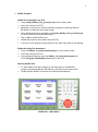
Starting RefSet Viva
To start RefSet Viva first minimise or exit from the Leica SmartWorx
program by pressing Fn then F5 (Minim) or F6 (Exit) at the start screen
Double tap the RefSet Viva shortcut on the windows desktop
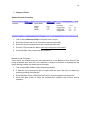
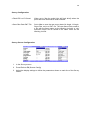
RefSet Viva - Main Menu
4
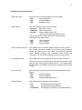
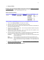
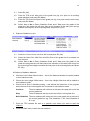
RefSet Program Configuration
Data File Type
Set to the type of control job files to use in RefSet:
STR
GSI
DXF
Data Folder
Surpac string file
Leica gsi data file
Autocad dxf file
Set to the location of the control job files:
SD Card
USB Stick
Internal
SD memory card
USB memory stick
Internal folder on the TPS
(\Leica Geosystems\SmartWorx Viva)
The control job files need to be saved in the following
subfolders of the Data Folder:
STR
GSI
DXF
Use Common Data File
‘Data’ subfolder
‘Gsi’ subfolder
‘Data’ subfolder
Set to Yes to use a common data file name for every function
The Control Job name chosen in one function (eg: Stakeout
Rings) will also be set in the other functions (eg: Stakeout
Holes, Stakeout Refline, etc). Otherwise each function will
‘remember’ the Job name chosen previously in that function
Log Staked Points
Set to Yes to save the automatic stakeout points to a log file
The points staked in all automatic modes will be saved to a file
with the same name as the control job with ‘_log’ added which
will be saved in a subfolder named ‘Log’ under the current Data
Folder
Log File Type
Set to the type of log file to save the automatic stakeout point
data to:
STR
GSI
CSV
Grade Display
Surpac string file
Leica gsi data file
Comma separated text file
Sets the input and output format for grades:
H:V
V:H
%(V/Hx100)
Horizontal by vertical distance
Vertical by horizontal distance
Percentage of vertical by horizontal distance
5
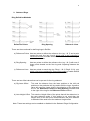
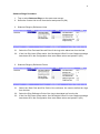
2. Stakeout Rings
Ring Definition Methods
Reference Points
Ring Spacing
Reference Lines
There are three methods for defining rings in RefSet:
a) Reference Points Has two points to define the reference line (eg: 1 & 7) and a point
located on each ring (eg: 2 to 6) which need to be numbered in
consecutive order to enable RefSet to increment to the next ring in
auto stakeout mode
b) Ring Spacing
Has two points to define the reference line (eg: 1 & 2) with one of
those points located on the first ring and a spacing between the
rings
c) Reference Lines
Has two points on each ring (eg: Ring1: 1 & 2, Ring2: 3 & 4, etc)
which need to be numbered in consecutive order to enable RefSet
to increment to the next ring in auto stakeout mode
There are two offset values that can be pre-set for the ring stakeout:
a) Rig Laser Offset
This sets the distance from the laser position to the drill rod
position on the particular drill rig used to drill the rings. A positive
value will move the Laser Lines in the direction of the reference
line for the Reference Points and Ring Spacing methods and
to the right of the ring for the Reference Lines method
b) Auto Height Offset This sets the Height offset of the points that will be staked out in
the auto stakeout mode. If this setting is not used then the
Height value of the first point measured when the auto stakeout
is started will be used to set the stakeout Height offset
Note: These two settings can be enabled or disabled in the Stakeout Rings Configuration
6
Stakeout Rings Procedure
1.
Tap or select Stakeout Rings on the start menu screen
2.
Select the Control Job to use from the list and press F1 (OK)
3.
Stakeout Rings by Reference Lines
3.1. Select the First Point and Second Point of the ring to be staked out from the lists
3.2. If the Use Rig Laser Offset and/or Use Set Height Offset For Auto Stakeout settings
have been set in the Configuration then enter these values and press F1 (OK)
3.
Stakeout Rings by Reference Points
3.1. Select the Start Point and End Point of the reference line used to define the rings
from the lists
3.2. Select the Ring Reference Point of the ring to be staked out from the list
3.3. If the Use Rig Laser Offset and/or Use Set Height Offset For Auto Stakeout settings
have been set in the Configuration then enter these values and press F1 (OK)
7
3.
Stakeout Rings by Ring Spacing
3.1. Select the Start Point and End Point of the reference line used to define the rings
from the lists
3.2. Enter the Ring Spacing of the rings
3.3. The Ring Numbers will then be generated from the reference line points and the
ring spacing – ring number one will be located at the Start Point of the reference
line
3.4. Select the Ring Number of the ring to be staked out from the list
3.5. If the Use Rig Laser Offset and/or Use Set Height Offset For Auto Stakeout settings
have been set in the Configuration then enter these values and press F1 (OK)
All Stakeout Rings Methods
4.
Choose the Auto Stake Pattern to use:
LRLR....
LRRL....
One Side
5.
Will stakeout the left wall, right wall, left wall, etc
Will stakeout the left wall, right wall, right wall, left wall, etc
Will stakeout the wall on which the auto stakeout is started
Point the TPS towards the first ring on the wall to be staked
For the LRLR.... and LRRL.... patterns the auto stakeout needs to always be started
with the TPS pointing towards the left wall - that is standing behind the instrument
facing the first ring to be staked out then the left wall is the one to the left
For all patterns the auto stakeout needs to be started at a point on the wall that is as
near to the first ring position as is possible
6.
Press F3 (Start Auto) to start the auto stakeout
8
Stakeout Rings Configuration
Start Dist Measure
Set to Yes to start distance measuring when the function starts
Auto Offset Accuracy
Sets the accuracy at which the Offset value is staked out in
auto stakeout mode
(eg: if set to 0.025 the TPS will stake the rings/laser lines Offset
value to within ±25mm before moving to the next ring)
Auto Height Accuracy
Sets the accuracy at which the Height value is staked out in
auto stakeout mode
(eg: if set to 0.200 the TPS will stake the rings/laser lines
Height value to within ±200mm before moving to the next ring)
Auto Wait Time (secs)
Sets the time the TPS will stop on an auto stakeout point when
it has been successfully staked out
(eg: if set to 5 the TPS will wait 5 seconds after it stakes out a
point before it moves on to the next ring)
Maximum Auto Search Time (secs)
Sets the maximum time the TPS will search for an auto
stakeout point. If set to zero the search time is infinite
(eg: if set to 30 the TPS will search for 30 seconds and if the
point is not found it moves on to the next ring)
Ring Stakeout Method
Sets the method for defining the rings (see the Ring Definition
Methods above):
Reference Lines
Reference Points
Ring Spacing
Use Rig Laser Offset
Set to Yes to enable a Rig Laser Offset to be set and applied to
the ring positions
Use Set Height Offset For Auto Stakeout
Set to Yes to enable the Height offset of the rings/laser lines
staked in auto mode to be staked at a set value, set to No to
stake the rings/laser lines at the Height offset of the first point
measured when the auto stakeout is started
9
3. Stakeout Holes
Blast holes are defined by two points on each hole, the hole design collar and the hole
design toe. (eg: Hole1: 1 & 2, Hole2: 3 & 4, etc) These points need to be numbered in
consecutive order to enable RefSet to increment to the next hole in auto stakeout mode
Stakeout Holes Procedure
1.
Tap or select Stakeout Holes on the start menu screen
2.
Select the Control Job to use from the list and press F1 (OK)
3.
Select the Hole Collar Point and Hole Toe Point of the hole to be staked out from the
lists and press F1 (OK)
4.
Point the TPS towards the wall near to the first hole to be staked
5.
Press F3 (Start Auto) to start the auto stakeout
Missed Holes Procedure
If any holes are missed during the auto stakeout due to the Maximum Auto Search Time
being exceeded then when the auto stakeout is stopped or finished a message will be
shown asking to stake the missed holes manually
1.
Tap or select Yes or No to stake the holes manually
2.
If Yes the collar and toe points for the first missed hole will be loaded and the hole
can then be staked by manually pointing the telescope
3.
Press F5 (Next Hole) or F4 (Previous Hole) to cycle through the missed holes
4.
Press F6 (New Hole) to finish the missed hole stakeout and resume normal operation
10
Stakeout Holes Configuration
Start Dist Measure
Set to Yes to start distance measuring when the function starts
Auto Position Accuracy Sets the accuracy at which the Offset and Perp Height values
are staked out in auto stakeout mode
(eg: if set to 0.025 the TPS will stake the holes Offset and Perp
Height values to within ±25mm before moving to the next hole)
Auto Wait Time (secs)
Sets the time the TPS will stop on an auto stakeout point when
it has been successfully staked out
(eg: if set to 5 the TPS will wait 5 seconds after it stakes out a
point before it moves on to the next hole)
Maximum Auto Search Time (secs)
Sets the maximum time the TPS will search for an auto
stakeout point. If set to zero the search time is infinite
(eg: if set to 30 the TPS will search for 30 seconds and if the
point is not found it moves on to the next hole)
11
4. Stakeout Refline
Reference Lines (centrelines) are defined by two points, these points need to be numbered
in consecutive order to enable RefSet to increment to the next refline in auto stakeout
mode (eg: First Refline: 1 & 2, Second Refline 2 & 3, etc)
Stakeout Refline Procedure
1.
Tap or select Stakeout Refline on the start menu screen
2.
Select the Control Job to use from the list and press F1 (OK)
3.
Select the Start Point and End Point of the reference line (centreline) to be staked out
from the lists and press F1 (OK)
4.
Check the Auto Stake Interval value – this is the slope distance between the points
staked in auto stakeout mode
5.
Check the Auto Stake Offset value – this is the Offset that will be staked in auto
stakeout mode (eg: for a centreline it will be zero)
6.
Check the At End of Refline setting – this defines the behaviour of the program when
the end of the current reference line is reached in auto stakeout mode
Continue
The auto stakeout will continue on the same line past the end of the
current reference line
Stop
The auto stakeout will stop at the end of the current reference line
Next Refline
The auto stakeout will increment to the next reference line at the end
of the current reference line (eg: First Refline: 1 & 2, Next Refline 2 &
3, etc)
7.
Point the TPS towards the wall or backs near to the reference line at a position near
where you want to start the stakeout
8.
Press F3 (Start Auto) to start the auto stakeout
12
Stakeout Refline Configuration
Start Dist Measure
Set to Yes to start distance measuring when the function starts
Auto Offset Accuracy
Sets the accuracy at which the Offset value is staked out in
auto stakeout mode
(eg: if set to 0.025 the TPS will stake the reference line Offset
value to within ±25mm of the Auto Stake Offset value before
moving to the next point on the refline)
Auto Interval Accuracy Sets the accuracy at which the slope distance interval between
the points is staked out in auto stakeout mode
(eg: if set to 0.200 the TPS will stake the points on the
reference line to within ±200mm of the Auto Stake Interval
setting from the previous point before moving to the next point)
Auto Wait Time (secs)
Sets the time the TPS will stop on an auto stakeout point when
it has been successfully staked out
(eg: if set to 5 the TPS will wait 5 seconds after it stakes out a
point before it moves on to the next point)
Maximum Auto Search Time (secs)
Sets the maximum time the TPS will search for an auto
stakeout point. If set to zero the search time is infinite
(eg: if set to 30 the TPS will search for 30 seconds and if the
point is not found it moves on to the next point)
13
5. Stakeout Gradeline
There are three methods for defining grade lines in RefSet:
a) Line
Uses two design points from the Control Job, these points need to
be numbered in consecutive order to enable RefSet to increment to
the next grade line in auto stakeout mode (eg: First Gradeline: 1 &
2, Second Gradeline 2 & 3, etc)
b) Measured Line
Uses two measured temporary points which will not be saved in a
Control Job and optionally an entered grade
c) Arc
Uses three design points from the Control Job to define an arc
Stakeout Gradeline Procedure
1.
Tap or select Stakeout Gradeline on the start menu screen
2.
Select the method to Define Gradeline By
3.
Stakeout Gradeline by Line
3.1. Select the Control Job to use from the list and press F1 (OK)
3.2. Select the Start Point and End Point of the grade line to be staked out from the
lists
3.3. Select Yes or No to Enter Gradeline Grade and if Yes enter the grade of the
grade line (the grade line will then start at the elevation of the start point and go
towards the end point at the entered grade) and press F1 (OK)
3.
Stakeout Gradeline by Measured Line
14
3.1. Press F1 (OK)
3.2. Point the TPS at the start point of the grade line (eg: at a point on an existing
grade paintline) and press F1 (Meas)
3.3. Point the TPS at the end point of the grade line (eg: at a point near the drive face)
and press F1 (Meas)
3.4. Select Yes or No to Enter Gradeline Grade and if Yes enter the grade of the
grade line (the grade line will then start at the elevation of the start point and go
towards the end point at the entered grade) and press F1 (OK)
3.
Stakeout Gradeline by Arc
3.1. Select the Control Job to use from the list and press F1 (OK)
3.2. Select the Start Point, Mid Point and End Point of the grade line to be staked out
from the lists
3.3. Select Yes or No to Enter Gradeline Grade and if Yes enter the grade of the
grade line (the grade line will then start at the elevation of the start point and go on
an arc through the midpoint towards the end point at the entered grade) and press
F1 (OK)
All Stakeout Gradeline Methods
4.
Check the Auto Stake Interval value – this is the distance between the points staked
in auto stakeout mode
5.
Check the Auto Height Offset value – this is the Height offset that will be staked in
auto stakeout mode
6.
Check the At End of Gradeline setting – this defines the behaviour of the program
when the end of the current grade line is reached in auto stakeout mode
Continue
The auto stakeout will continue on the same line past the end of the
current grade line
Stop
The auto stakeout will stop at the end of the current grade line
Next Gradeline The auto stakeout will increment to the next grade line at the end of
the current grade line (eg: First Gradeline: 1 & 2, Next Gradeline 2
& 3, etc)
7.
Point the TPS towards the wall at a position near where you want to start the
stakeout
8.
Press F3 (Start Auto) to start the auto stakeout
15
Stakeout Gradeline Configuration
Start Dist Measure
Set to Yes to start distance measuring when the function starts
Auto Height Accuracy
Sets the accuracy at which the Height value is staked out in
auto stakeout mode
(eg: if set to 0.025 the TPS will stake the grade line Height
value to within ±25mm of the Auto Height Offset value before
moving to the next interval on the grade line)
Auto Interval Accuracy Sets the accuracy at which the distance Interval between the
points is staked out in auto stakeout mode
(eg: if set to 0.200 the TPS will stake the points on the grade
line to within ±200mm of the Interval setting from the previous
point before moving to the next interval)
Auto Wait Time (secs)
Sets the time the TPS will stop on an auto stakeout point when
it has been successfully staked out
(eg: if set to 5 the TPS will wait 5 seconds after it stakes out a
point before it moves on to the next point)
Maximum Auto Search Time (secs)
Sets the maximum time the TPS will search for an auto
stakeout point. If set to zero the search time is infinite
(eg: if set to 30 the TPS will search for 30 seconds and if the
point is not found it moves on to the next point)
16
6. Stakeout Laser
Stakeout Laser Procedure
1.
Tap or select Stakeout Laser on the start menu screen
2.
Select the Control Job to use from the list and press F1 (OK)
3.
Select the Start Point and End Point of the laser design reference line to be staked
out from the lists or press F6 (Map) and select the points there
4.
Select Yes or No to Enter Laser Grade and if Yes enter the grade of the laser (the
laser design reference line will then start at the elevation of the start point and go
towards the end point at the entered grade) and press F1 (OK)
5.
Stakeout Laser on Curve
5.1. In the Stakeout Laser screen - press F6 (Map) to go to the map view and then
window in the map to the relevant area
5.2. Point the TPS towards the drive wall at a good position for the laser and Press F2
(Dist) to start measuring - the measured position will then be shown on the map
view with a blue dashed line showing the offset line from the laser design
reference line
5.3. While measuring, turn the TPS and/or reselect the laser design reference line
Start and End Points (by tapping on or near a point symbol) to adjust the dashed
offset line to the best position for the laser - including using the displayed Ht OS
value to position the laser vertically
5.4. When the best laser position has been found, mark the position on the drive wall
and then press F6 (Stake) to go back to the laser stake view
5.5. With the TPS still pointing towards the laser position, press F1 (Meas Laser) - the
TPS will then measure the laser position and set the Auto Stake Offset and Auto
Height Offset values on the stake screen to the measured values
17
5.6. Point the TPS towards the drive face near to the laser target position and press F3
(Start Auto) to start the auto stakeout of the laser target position
5.
Stakeout Laser on Straight
5.7. In the Stakeout Laser screen - enter the Auto Stake Offset value and check the
Auto Height Offset value - these are the values that will be staked out in the auto
stakeout mode
5.8. Point the TPS towards the drive wall near to the laser position and press F3 (Start
Auto) to start the auto stakeout of the laser position
5.9. When the laser position has been established and marked point the TPS towards
the drive face near to the laser target position and press F3 (Start Auto) to start
the auto stakeout of the laser target position
18
Stakeout Laser Configuration
Start Dist Measure
Set to Yes to start distance measuring when the function starts
Auto Position Accuracy
Sets the accuracy at which the Offset and Height Offset values
are staked out in auto stakeout mode
(eg: if set to 0.005 the TPS will stake the laser point Offset and
Height Offset values to within ±5mm)
Default Auto Height OS
The Auto Height Offset value that is used for the auto stakeout
will be reset to this value when the function starts
19
7. Stakeout Points
Stakeout Points Procedure
1.
Tap or select Stakeout Points on the start menu screen
2.
Select the Control Job to use from the list and press F1 (OK)
3.
Select the Point to Stakeout from the list and press F1 (OK)
4.
Point the TPS towards the backs near to the first point to be staked
5.
Press F3 (Start Auto) to start the auto stakeout
Missed Points Procedure
If any points are missed during the auto stakeout due to the Maximum Auto Search Time
being exceeded then when the auto stakeout is stopped or finished a message will be
shown asking to stake the missed points manually
1.
Tap or select Yes or No to stake the points manually
2.
If Yes the first missed point will be loaded and the point can then be staked by
manually pointing the telescope
3.
Press F5 (Next Point) or F4 (Previous Point) to cycle through the missed points
4.
Press F6 (New Point) to finish the missed point stakeout and resume normal
operation
20
Stakeout Points Configuration
Turn to Point at Start
Set to turn the TPS towards the stakeout point when the
function starts:
Yes – 2D Turns the horizontal axis only
Yes – 3D Turns both the horizontal and vertical axis
No
Does not turn the TPS
Start Dist Measure
Set to Yes to start distance measuring when the function starts
Auto Position Accuracy Sets the accuracy at which the Length and Cross offset values
are staked out in auto stakeout mode
(eg: if set to 0.025 the TPS will stake the points Length and
Cross values to within ±25mm before moving to the next point)
Auto Wait Time (secs)
Sets the time the TPS will stop on an auto stakeout point when
it has been successfully staked out
(eg: if set to 5 the TPS will wait 5 seconds after it stakes out a
point before it moves on to the next point)
Maximum Auto Search Time (secs)
Sets the maximum time the TPS will search for an auto
stakeout point. If set to zero the search time is infinite
(eg: if set to 30 the TPS will search for 30 seconds and if the
point is not found it moves on to the next point)
21
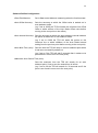
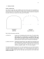
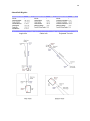
8. Stakeout Profile
Profile Job Data Files
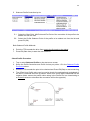
The Profile Job data files used in RefSet need to be setup in plan view coordinates (ie:
Easting=Drive Width and Northing=Drive Height) with the coordinate origin (0E,0N) located
at the centreline point of the profile. Note: The centreline does not need to be located on
the profile outline (eg: it may be at the centre point of the profile).
Profile File
Stakeout Point File
Each Profile Job needs two data files:
a) Profile File
Contains the full (detailed) profile outline string. The profile outline
string needs to be a closed string in a clockwise direction. The
point numbering is not important (eg: the point id’s of the string
may be blank). This outline is used to calculate the Profile Offset
which is the shortest distance between a measured point and the
profile and can be used to check for overbreak and underbreak.
b) Stakeout Point File
Contains the points that are to be staked out on the face in the
auto stakeout mode. These points need to have individual point
id’s in consecutive order. Note: These points do not need to be
located on the profile outline (eg: there can be a point on the
centreline at gradeline height - Pt 1 in the above diagram).
The Profile Job data files need to be in the same format that is set in the Data File Type in
the RefSet Program Configuration (ie: str, gsi or dxf). These files need to be located in a
subfolder of the data files folder called Profiles. (ie: for str and dxf files the files need to be
located in the Profiles folder under the Data folder and for gsi files in the Profiles folder
under the GSI folder)
22
Profile Job Data Files Setup Procedure
1.
Create a Profiles folder on the memory card under the data folder
for the Data File Type set in RefSet (ie: for str and dxf files under
the Data folder and for gsi files under the GSI folder)
2.
Create a profile outline string (see diagram above) and ensure the
profile outline string is a closed string in a clockwise
direction
3.
Use this string to create the Profile File in the same Data File Type
set in RefSet and ensure that this file contains only the outline
string
4.
The Profile File needs to be named with a ‘_profile’ suffix (eg: 5x5_profile.gsi)
5.
Create the profile stakeout points to be staked out on the face (see diagram above)
and ensure these points have individual point id’s in consecutive order
6.
Use these points to create the Profile Stakeout Point File in the same Data File Type
set in RefSet
7.
The Stakeout Point File needs to be named with the same name as the Profile
File but with a ‘_stake’ suffix (eg: 5x5_stake.gsi)
8.
Copy both the Profile File and the Stakeout Point File to the Profiles folder on the
memory card (Note: These two files will represent one Profile Job in RefSet)
Stakeout Profile Procedure
1.
Tap or select Stakeout Profile on the start menu screen
2.
Select the method to Define Centreline By
3.
Select the Control Job to use from the list
4.
Select the Profile Job to use from the list and press F1 (OK)
5.
Stakeout Profile Centreline by Line
5.1. Select the Start Point and End Point of the centreline of the profile to be staked
out from the lists
5.2. Select the Profile Stakeout Point to be staked out from the list and press F1 (OK)
23
5.
Stakeout Profile Centreline by Arc
5.1. Select the Start Point, Mid Point and End Point of the centreline of the profile to be
staked out from the lists
5.2. Select the Profile Stakeout Point of the profile to be staked out from the list and
press F1 (OK)
Both Stakeout Profile Methods
6.
Point the TPS towards the drive face near to the first point to be staked
7.
Press F3 (Start Auto) to start the auto stakeout
Check Profile Procedure
1.
Tap or select Stakeout Profile on the start menu screen
2.
Setup the Profile Centreline and Profile Job as per points 1-5 in the Stakeout Profile
Procedure above.
3.
Point the TPS towards the point to be checked and Press F2 (Dist) to start measuring
4.
The Offset from Profile value can be used to check for overbreak and underbreak of
the drive. Overbreak will have a positive Offset from Profile while underbreak will be
negative (Note: ensure the profile outline string in the Profile File is a closed string in
a clockwise direction otherwise this convention will be the opposite)
24
Stakeout Profile Configuration
Start Dist Measure
Set to Yes to start distance measuring when the function starts
Auto Position Accuracy Sets the accuracy at which the stakeout point Offset and Perp
Height values are staked out in auto stakeout mode
(eg: if set to 0.025 the TPS will stake the profile stakeout point
Offset and Perp Height values to within ±25mm before moving
to the next stakeout point)
Auto Wait Time (secs)
Sets the time the TPS will stop on an auto stakeout point when
it has been successfully staked out
(eg: if set to 5 the TPS will wait 5 seconds after it stakes out a
point before it moves on to the next point)
Maximum Auto Search Time (secs)
Sets the maximum time the TPS will search for an auto
stakeout point. If set to zero the search time is infinite
(eg: if set to 30 the TPS will search for 30 seconds and if the
point is not found it moves on to the next point)
Auto Search Limit (m)
Sets the distance limit for the point search in the auto stakeout
mode. The auto stakeout will be restricted to within this
distance from the start point of the auto stakeout
25
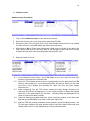
9. Survey
Survey Procedure
1.
Tap or select Survey on the start menu screen
2.
Select the Working Job to use from the list or press F3 (Create New Job) to create a
new working job file
3.
Press F1 (OK)
4.
Press F1 (Meas) to measure and store the point using the Reflectorless Standard
EDM mode - this method can be used where more accuracy is needed
5.
Press F2 (Dist) to start measuring using the Reflectorless Continuous EDM mode
and then press F3 (Store) to store the measured point - this method can be used
where more speed is needed
Note: When F3 (Store) is pressed the TPS will not store the point until it has
measured two shots that are within 50mm - this ensures that the stored point
coordinates are not affected by any large TPS movements during measurement
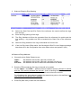
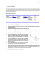
Measured Point Offsets
1.
Press F5 (Offsets) to enter and apply offsets to the
measured points
2.
Select the Offset Mode to use. Select Reset After
Store to apply the offsets to a single measured point
or select Permanent to apply the offsets to all
following measured points
6.
Enter the offsets to use for the following measured
point/s and then press F1 (OK)
26
Survey Configuration
Flash EGL on Pt Stored
When set to Yes the guide light will flash briefly when the
point has been stored as a visual indicator
Save Raw Data DAT File
Set to Yes to save the raw survey data (Hz Angle, Vt Angle,
Slope Dist, etc) to a DAT file. The raw data will be saved to
a file with the same name as the Working Job with a ‘.dat’
extension which will be saved in the same folder as the
Working Job file
Survey Screen Configuration
1.
In the Survey screen
2.
Press Fn then F2 (Screen Config)
3.
Adjust the display settings to define the parameters shown on each line of the Survey
screen
27
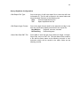
10. Survey Rig/Holes
The Survey Rig/Holes function can be used to either check the alignment (azimuth and dip)
of a drill rig setup (raise bore, blasthole rig, diamond drill rig, etc) or to survey completed
drill holes and produce a drill hole survey report with the collar coordinates, azimuth and
dip for each hole recorded.
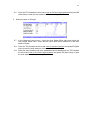
Survey Holes Procedure
1.
Tap or select Survey Rig/Holes on the start menu screen
2.
Select the Working Job to use from the list or press F3 (Create New Job) to create a
new working job file
3.
Select No to Compare to Design Hole and press F1 (OK)
4.
Select the Survey Type of the survey. Select Rod (2 Points) to measure 2 points on
a drill rod to calculate the azimuth and dip of the hole as well as the collar position of
the hole or select Collar (1 Point) to measure just the collar position
5.
Enter the Hole ID of the hole being surveyed
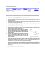
6.
If using the Rod Survey Type enter the Collar Offset
which is the slope distance from the front measured
point on the rod to the collar position in line with the
back measured point
7.
If using the Rod Survey Type point the TPS towards
the front point on the rod and press F1 (Meas), then
point the TPS towards the back point on the rod and
press F1 (Meas)
8.
If using the Collar Survey Type point the TPS towards
the collar point of the hole and press F1 (Meas)
9.
The measured hole information will then be displayed and will also be written to the
survey drill hole report file which is saved in the same folder and has the same
filename as the Working Job with either a ‘.csv’ or ‘.txt’ extension depending on the
DH Report File Type set in the Survey Rig/Holes Configuration
10. Press F1 (OK) to survey the next drill hole
28
Check Drill Rig Procedure
1.
Tap or select Survey Rig/Holes on the start menu screen
2.
Select the Working Job to use from the list or press F3 (Create New Job) to create a
new working job file
3.
Select Yes or No to Compare to Design Hole and then if Yes select the Control Job
to use from the list and press F1 (OK)
4.
If comparing to a design hole select the Design Hole Collar and Design Hole Toe
points from the lists and press F1 (OK)
5.
Select Rod (2 Points) for the Survey Type
6.
Enter the Hole ID of the drill rig survey - this is not really relevant for a drill rig check
so can be set to a dummy number (eg: 1)
7.
Enter the Collar Offset of the drill rig survey which is
the slope distance from the front measured point on
the rig or rod to the collar position in line with the back
measured point
8.
Point the TPS towards the front or bottom point on the
rig or rod and press F1 (Meas), then point the TPS
towards the back or top point on the rig or rod and
press F1 (Meas)
9.
The drill rig check information will then be displayed and will also be written to the
survey drill hole report file which is saved in the same folder and has the same
filename as the Working Job with either a ‘.csv’ or ‘.txt’ extension depending on the
DH Report File Type set in the Survey Rig/Holes Configuration
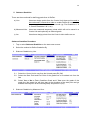
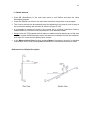
Note: If comparing to a design hole the drill rig check information includes the
Projected Toe coordinates. These coordinates are calculated using the measured dip
and azi and projecting the hole from the collar position for the same length as the
design hole
10. Press F1 (OK) to resurvey the drill rig check
29
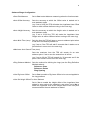
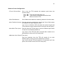
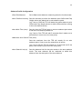
Check Drill Rig Info
Angle Info
Collar Info
Projected Toe Info
30
Survey Rig/Holes Configuration
DH Report File Type
Set to the type of drill hole report file to save the drill hole
information to. This file will be saved in the same folder and
have the same filename as the Working Job:
CSV
TXT
DH Report Angle Format
Comma separated text file
Space separated text file
Set to the angle format used for the azimuth and dip in the
drill hole information display and the drill hole report file:
Deg Min Sec
Decimal Deg
Save Raw Data DAT File
Degrees, minutes, seconds
Decimal degrees
Set to Yes to save the raw survey data (Hz Angle, Vt Angle,
Slope Dist, etc) to a DAT file. The raw data will be saved to
a file with the same name as the Working Job with a ‘.dat’
extension which will be saved in the same folder as the
Working Job file
31
11. RefSet General
Press F5 (SmartWorx) in the main start menu to exit RefSet and start the Leica
SmartWorx program
Press Fn, F6 (Quit) to return to the main start menu from any screen in the program
The Control Job lists can be searched using the alpha keys (eg: press 3 once to jump to
the control jobs starting with the letter D, twice to jump to E, etc)
It is important to number the points in the control job in a logical consecutive order to
enable RefSet to increment to the next feature in auto stakeout modes
Always point the TPS towards the first feature to stakeout before starting any of the auto
stakeout modes, RefSet basically uses a trial and error method to do the auto stakeout,
so it helps if it is near the first feature when it starts
In the Measure New Point function pressing Meas will measure the point in standard
reflectorless mode, while pressing Dist will measure in reflectorless continuous mode
Reference Line Offsets Description
32
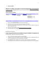
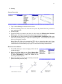
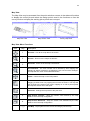
Map View
The Map View may be accessed from the point selection screens in the stakeout functions
to display the control job and select the design point/s used in the functions or from the
survey function to display the working job as points are surveyed.
Map Plan View
Map Section View
Survey Map View
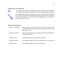
Map View Menu Functions
Icon
Key
Description
1
Zoom All – Fits all the map data to the screen
2
Zoom In - Zoom in to the map a set amount
3
Zoom Out - Zoom out of the map a set amount
Zoom Window - The zoom window can be defined by either tapping and
dragging to draw a rectangle or by tapping the two corners of the rectangle.
The map will then zoom to the selected window
Centre - Centre the map on the TPS position
Section View - The section view can be defined by either tapping and
dragging to draw a line or by tapping the two ends of the line. The map will
then change to the section view. Note: Tapping on or near a point symbol
will snap the section line to that point
Plan View - Change the map back to the plan view
6
Step Section Forward - Steps the section view forward by the step
distance set in the map configuration
4
Step Section Backward - Steps the section view backward by the step
distance set in the map configuration
←↑↓→
Pan Map - Tap anywhere on the screen and drag to pan the map
33
Design Point / Line Selection
The design points used in the stakeout functions can be selected by tapping
on or near a point symbol. The point will then be highlighted with a blue box
The design lines used in the stakeout functions can be selected by tapping
on or near a point symbol and will alternate from the start point of the line to
the end point of the line. The line will then be highlighted in blue with the line
direction show by an arrow
Map View Configuration
Section View Width
Sets the width of the section view. Only points and lines that
are within this width around the section line will be visible in the
map section view
Section View Step
Sets the step distance when stepping forward and backward in
the map section view
Display Points
Set to Yes to display the points in the map view
Display Point IDs
Set to Yes to display the point IDs of the points in the map view
Display Lines
Set to Yes to display the lines in the map view