1
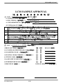
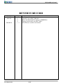
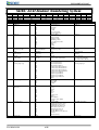
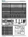
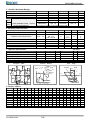
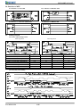
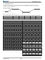
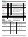
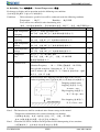
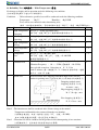
DOT MATRIX
LIQUID CRYSTAL DISPLAY
MODULE
COMPANY NAME:
:
Electus
USER‘MANUAL
QP5516
LCD Module Description:QP5516
PROPOSED BY
Design
APPROVED
Approved
Jan Lu
SC01602M0-01 Serial
LCM SAMPLE APPROVAL
(液
晶
顯
示
模
組
樣
品
確
認
書)
(由 SDEC 填寫
填寫)
)
1. PART A:FILLED BY SDEC TECH(
1) COMPANY NAME(
(客戶名稱):
客戶名稱):____ELetus_______________
):
2) SDEC ITEM NO.(
(產品型號):
產品型號):__SCS01602M0FLY10_____________
):
3) CUSTOMER ITEM NO.(
(客戶產品型號):
客戶產品型號):__
):__QP5516______________
__
______________
4) LCM Function (LCM 內容):
內容 :
LCD TYPE (LCD 種類
種類):
:□ TN, □ HTN, ■ STN, □ FSTN, □ DFSTN
( □ POSITIVE/正向
正向,
反向, □ BLACK MASK/內黑絲印
內黑絲印)
正向, □ NEGATIVE/反
內黑絲印
B
VIEWING AREA (視角方向
視角方向):
:□ 3H, ■ 6H, □ 9H, □ 12H
視角方向
C
POLARIZER COLOR (偏光板顏色
偏光板顏色):
灰色, ■ YELLOW GREEN/黃綠色
黃綠色,
偏光板顏色
:□ GRAY/灰色
灰色
黃綠色
□ BLUE/藍色
藍色, □ BLACK/黑色
藍色
黑色
D
BACKLIGHT COLOR (背光顏色
背光顏色):
:■ YELLOW GREEN/黃綠光
黃綠光, □ ORANGE/橘光
背光顏色
黃綠光
橘光
□AMBER/琥珀光
琥珀光,
紅光, □BLUE/藍光
藍光, □GREEN/翠綠光
翠綠光, □WHITE/白光
白光,
,
琥珀光 □RED/紅光
紅光
藍光
翠綠光
白光
專利白光
雙色光, □ RGB/三色光
□WHITE(Patent)/專利
專利白光,
白光, □DOUBLE COLOR/雙色光
雙色光
三色光
E
TEMPERATURE (溫度
溫度):
:□ NORMAL/常溫
常溫, ■ WIDE/廣溫
溫度
常溫
廣溫
F
CONTROL IC (控制
:SPLC780D1-01
控制 IC):
SAMPLE DELIVERY DATE(
(出樣日期
出樣日期):
):__
):__2014.06.25___________
__
___________
A
(請客戶填寫)
請客戶填寫)
2.PART B:FILLED BY CUSTOMER(
OK NG
CHECK LIST ITEMS(
(檢查項目):
檢查項目):
REASON(
(原因
原因)
)
1).LCM SIZE AND THICKNESS:(LCM 尺寸及厚度)
:
尺寸及厚度)
□
□
________
2).POLARIZER COLOR:(
:(偏光板色澤
:(偏光板色澤):
偏光板色澤):
□
□
________
3).ELECTRO CHARACTERISTIC:(
:(電氣特性
:(電氣特性):
電氣特性):
□
□
________
4).VIEWING AREA(
(視角範圍):
視角範圍):
□
□
________
5).BACKLIGHT ILLIMINATION(
(背光亮度):
背光亮度):
□
□
________
6).TEMPERATURE RANGE(
(溫度範圍
溫度範圍):
):
□
□
________
APPROVED BY(
(批准):
批准):
DATE OF APPROVAL(
(批准日期):
批准日期):
__________________
________________________
Ver 2014.06.24
2/19
SC01602M0-01 Serial
REVISION RECORD
Revision
2010.07
2011.10
2014.06.24
Ver 2014.06.24
Page
2
6
8
1、2
Contents
First Release Version
Control IC Set to SPLC780D1-01
White Color Backlight Lift change to 20,000 Hour.
Timing Control change for SPLC780D1
Added Electus customer item number
3/19
SC01602M0-01 Serial
SDEC LCD Module Numbering System
1
S
S
S
2
C
G
D
3
S
F
H
4
5
040
320
007
Numbering System
1
Company
2
LCM type
S
G
3
LCD type
S
4,5,6
Row dots number
Characters per line
Year
Column dots
number Lines
Month
LCD module
serial number
128
7,8
9,10
64
7
8
04
24
08
9
10
A0
A0
A0
11
H
J
B
Code Value
S
B
C
G
O
T
S
D
T
H
S
F
D
R
M
V
A
L
122,128,240,320...
008,016,020,040...
006,007...
32,64,128,240...
01,02,04...
01,02..12
Description
Company name abbreviated
B:Big Character
C:Character
G:Graphic
O:COG
T:TAB
S:Seven Segment
D:Customer Design
TN type LCD
HTN type LCD
STN type LCD
FSTN type LCD
DFSTN type LCD
Color TN / Color STN
TFT LCD
VFD
VATN
OLED
Row dots number
Characters per line
Year
Column dots number
Lines
Month
A0~ZZ
LCD module serial number
A
B
C
D
E
F
G
H
I
J
K
L
M
N
L
E
C
F
N
O
A
B
G
R
Y
W
P
D
T
0
1
2
3
A
B
C
F
U
Z
0~Z
Gray Mode/3:00view
Gray Mode/6:00view
Gray Mode/9:00view
Gray Mode/12:00view
Yellow Green Mode/3:00view
Yellow Green Mode/6:00view
Yellow Green Mode/9:00view
Yellow Green Mode/12:00view
Negative type/3:00view
Negative type/6:00view
Negative type/9:00view
Negative type/12:00view
Other
Without backlight
Array LED
Edge LED
C.C.F.L
EL
Without backlight
Orange
Amber
Blue
Green
Red
Yellow-green
White
White(Patent)
Double Color(Y-G&R)
RGB
No Font Table
English-Japanese Font Code
English-Europe Font Code
English-Russian Font Code
BIG-5 Chinese Font Code
GB Chinese Font Code
ST7920-0C Font Code
ST7920-0F Font code (Korean)
Unicode
Other Font Code
A0
11
Polarizer Color
&
Viewing angle type
I
12
Backlight type
L
13
Backlight color
(VFD color)
Y
14
Font Code Type
0
15
Series Code
0
Ver 2014.06.24
6
12
L
C
N
13
T
W
N
15
0
0
0
Remark
SDEC CO.,LTD
LCM type
LCD type
Graphic
Character
Seven Segment
Graphic
Character
Seven Segment
Ux -> USB Port Interface
Sx ->Series Port Interface
Rx -> RS-232 Port Interface
Polarizer Color
&
Viewing angle type
Backlight type
Backlight color
Font Table Code Type
Series Code
4/19
14
1
1
0
SC01602M0-01 Serial
CONTENTS
PAGE
2
● LCM Sample Approval
● REVISION RECORD
● LCD Module Number System
3
4
Mechanical Specification
6
Mechanical Diagram
Interface Pin Connections
Block Diagram
Absolute Maximum Ratings
Electrical Characteristics
Optical Characteristics
Optical Definitions
Display Address
Interface to MPU
10.1 Interface to Z-80 CPU
10.2 Interface to MC6800 CPU
10.3 Interface to 4-bit CPU (HMCS43C)
10.4 Interface to HD6805 MP
6
6
6
7
7
7
7
7
8
8
8
8
8
1.
2.
3.
4.
5.
6.
7.
8.
9.
10.
11. Timing Control
11.1 Write and Read Operation
11.2 Busy flag check timing
8
8
8
12.
13.
14.
15.
Initialization of LCM
Instruction Set
User Font Patterns
Software Example
15.1 8-bit operation (8 bits 2 lines)
15.2 4-bit operation (4 bits 2 lines)
9
10
10
11
11
11
16.
17.
18.
19.
20.
21.
Character Generator ROM Map
Function Test & Inspection Criteria
Reliability Test – Normal Temperature
Reliability Test – Wide Temperature
Precautions Against Product Handling
Warranty
12
13
15
16
17
18
Ver 2014.06.24
5/19
SC01602M0-01 Serial
Mechanical Specification
ITEM
NUMBER OF CHARACTERS
CHARACTER FORMAT
MODULE DIMENSION
NO / EDGE LED BACKLIGHT
MODULE DIMENSION
ARRAY LED BACKLIGHT
MODULE DIMENSION
EDGE LED BACKLIGHT (BLUE)
VIEWING DISPLAY AREA
ACTIVE DISPLAY AREA
CHARACTER SIZE
CHARACTER PITCH
DOT SIZE
DOT PITCH
ARRAY LED BACKLIGHT COLOR
BACKLIGHT INPUT
BACKLIGHT HALF-LIFT TIME
EDGE LED BACKLIGHT COLOR
BACKLIGHT INPUT
BACKLIGHT HALF-LIFT TIME
EDGE LED BACKLIGHT COLOR
BACKLIGHT INPUT
BACKLIGHT LIFT TIME
Item
Forward Voltage
Reverse Current
Peak Wave Length
Chromaticity Coordinates
Luminance
1.
STANDARD VALUE
16 CHARACTERS X 2 LINES
5 X 8 DOTS
UNIT
---
85.0 (W) X 30.0 (H) X 9.5 (T)
mm
85.0 (W) X 30.0 (H) X 13.2 (T)
mm
85.0 (W) X 30.0 (H) X 11.5 (T)
mm
65.0 (W) X 16.0 (H)
mm
56.21 (W) X 11.50 (H)
mm
2.95 (W) X 5.55 (H)
mm
3.55 (W) X 5.95 (H)
mm
0.55 (W) X 0.65 (H)
mm
0.60(W) X 0.70 (H)
mm
YELLOW GREEN OR ORANGE OR RED
DC +4.0V
V
100 (Type)
mA
30,000 (Ta=25 )
HR.
YELLOW GREEN
DC+4.0V
V
26 (Type)
mA
20,000 (Ta=25 )
HR.
BLUE OR GREEN OR WHITE
DC +4.0V
V
26 (Type)
mA
20,000 (AVOID LIGHTING CONTINUOUSLY Ta=25 )
HR.
LED Backlight Characteristics (without LCD)
Ta=25
Min.
Type
Max.
Unit
Condition
V
If= mA
--A
If= mA
---nm
If= mA
X=
Y=
If= mA
--cd/m2
If= mA
℃
℃
,
℃
μ
Mechanical Diagram
A
K
LED
BACKLIGHT
TYPE
3. Interface Pin Connections
NO
1
2
3
4
5
6
7
8
9
10
11
12
13
14
SYMBOL
VDD
VSS
VO
RS
R/W
E
DB0
DB1
DB2
DB3
DB4
DB5
DB6
DB7
A(+)
K(-)
Ver 2014.06.24
LEVEL
---H/L
H/L
H,H→L
H/L
H/L
H/L
H/L
H/L
H/L
H/L
H/L
DC+4.0V
0V
4. Block Diagram
FUNCTION
DC +5V
GND (0V)
Contrast Adjust
Register select
Read/Write
Enable signal
Data Bit 0
Data Bit 1
Data Bit 2
Data Bit 3
Data Bit 4
Data Bit 5
Data Bit 6
Data Bit 7
LED Backlight +
LED Backlight -
6/19
O
BACKL I GHT
T YPE
℃
SC01602M0-01 Serial
5. Absolute Maximum Ratings
ITEM
SYMBOL
MIN.
TYPE
INPUT VOLAGE
VI
VSS
──
SUPPLY VOLTAGE FOR LOGIC
VDD-VSS
──
5.0
SUPPLY VOLTAGE FOR
LCD
VDD-VO
──
──
NORMAL TEMPERATURE RANGE
OPERATING
0~+50
STORAGE
TN
HTN
WIDE TEMPERATURE RANGE
OPERATING
-20~+70
STORAGE
STN
WIDE TEMPERATURE RANGE
OPERATING
-20~+70
STORAGE
FSTN
STATIC ELECTRICITY
Be sure that you are grounded when handing LCM.
MAX.
VDD
6.5
6.5
-10~+60
-30~+80
UNIT
V
V
V
℃
℃
℃
-30~+80
6. Electrical Characteristics
ITEM
SUPPLY VOLTAGE FOR LOGIC
SYN
VDD-VSS
SUPPLY VOLTAGE FOR LCD
VDD-VO
INPUT HIGH VOLTAGE
INPUT LOW VOLTAGE
OUTPUT HIGH VOLTAGE
OUTPUT LOW VOLTAGE
SUPPLY CURRENT
VIH
VIL
VOH
VOL
IDD
CONDITION
──
Ta=0/-20℃
Ta=+25℃
Ta=+50/+70℃
──
──
──
──
VDD=+5V
MIN.
4.5
──
4.1
──
2.5
0
2.4
──
──
TYPE
5.0
4.6/4.8
4.3
4.0/3.9
──
──
──
──
3.0
MAX.
5.5
──
4.5
──
VDD
0.6
──
0.4
4.5
UNIT
V
V
V
V
V
V
V
V
mA
Ta at 25℃
7. Optical Characteristics
ITEM
VIEW ANGLE (TOP/BOTTOM)
VIEW ANGLE (LEFT/RIGHT)
CONTRAST RATIO
RESPONSE TIME (RISE)
RESPONSE TIME (DECAY)
SYM
θ2 / θ1
φ1 / φ2
CR
TON/Tr
TOFF/Tf
CONDITION MIN.
TYPE
CR≧2
── 15o / 35o(35o / 45o)
CR≧2
──
35o / 35o
──
──
4.5
──
──
170
──
──
220
MAX.
──
──
──
──
──
UNIT
deg.
deg.
──
mS
mS
8. Optical Definitions
Response
Time
Contrast
Contrast Ration (K) =
Ration
View
Brightness of
nonselected segment (B2)
────────────
Brightness of
Y(TOP)
selected segment (B1)
Nonselected
Condition
ss
en
th
gi
tB
Brightness curve
of nonselected
segment
Nonselected
Condition
Rise Time
θ2
EYE
θ1
X
(Left)
ss
net
hg
it Brightness
B curve of
selected
segment
Fall Time
Angle
X
(Right)
2
1
Y(BOTTOM)
Set Point Driving Voltage
9. Display Address
Line 1
Line 2
Line 3
Line 4
1
80
C0
2
81
C1
3
82
C2
4
83
C3
5
84
C4
6
85
C5
7
86
C6
8
87
C7
9
88
C8
10
89
C9
11 12
8A 8B
CA CB
13 14
8C 8D
CC CD
15
8E
CE
16
8F
CF
17
18
19
20
21
22
23
24
25
26
27
28
29
30
31
33
35
36
37
38
39
40
Line 1
Line 2
Line 3
Line 4
Ver 2014.06.24
7/19
32
34
SC01602M0-01 Serial
10. Interface to MPU
10.1 Interface to Z-80 CPU
10.2 Interface to MC6800 CPU
10.4 Interface to HD6805 MP
10.3 Interface to 4-bit CPU (HMCS43C)
11. Timing Control
11.1 Write and Read Operation
Write Operation
Item
Enable Cycle Time
Enable Pules Width ( High level )
Enable Rise/Fall Time
Address Set-Up Time ( RS,R/W,E )
Address Hole Time
Data Set-Up Time
Data Delay Time
Data Hold Time
Read Operation
Symbol
tCYCE
PWEH
tER,tEF
tAS
tAH
tDSW
tDDR
tDHR
Limit (Min.)
400
150
-30
10
40
-20
11.2 Busy flag check timing
Note: IR7, IR3: Instruction 7th bit, 3rd bit; AC3: Address Counter 3rd bit.
Ver 2014.06.24
8/19
Limit (Max.)
--25
---100
--
Unit
ns
ns
ns
ns
ns
ns
ns
ns
SC01602M0-01 Serial
12. Initialization of LCM
The LCM automatically initializes (reset) when power is turned on using the internal reset circuit. If the power supply
conditions for correctly operating of the internal reset circuit are not met, initialization by instruction is required. Use the
procedure is next page for initialization.
Internal Power Supply reset
4.5V
0.2V
Vcc
→
←
toff
trcc
←------→
(Note 1) 10 ms ≧ trcc ≧ 0.1 ms , toff ≧ 1 ms.
(Note 2) toff stipulates the time of power OFF for momentary power supply dip or when power supply cycles ON and OFF.
Item
Power supply rise time
Power supply off time
Symbol
trcc
toff
Test condition
---
Limit (Min.)
0.1
1
↓
↓
Power ON
Power ON
RS
0
DD
Wait more than 15ms after VDD rises to 0.9VDD
rises to 0.9VDD
Function Set
R/W DB7 DB6 DB5 DB4 DB3 DB2 DB1 DB0
0
0
0
1
1
*
*
*
*
↓
↓
RS
0
R/W
0
Wait more than 4.1 ms
RS
0
Wait more than 100
RS
0
RS
0
R/W
0
μs
↓
↓
Function Set
DB7
DB6
0
0
↓
↓
Wait more than 100
Function Set
R/W DB7 DB6 DB5 DB4 DB3 DB2 DB1 DB0
0
0
0
1
1
*
*
*
*
Wait more than 100
Function Set
DB7
DB6
0
0
DB5
1
DB4
1
DB5
1
DB4
1
DB5
1
DB4
1
Wait more than 4.1 ms
Function Set
R/W DB7 DB6 DB5 DB4 DB3 DB2 DB1 DB0
0
0
0
1
1
*
*
*
*
↓
↓
Unit
ms
ms
(b) 4-bit interface
(a) 8-bit interface
↓
Wait more than 15ms after V
↓
Limit (Max.)
10
--
↓
μs or Busy Flag Check
↓
RS
0
R/W
0
Function Set
DB7
DB6
0
0
Wait more than 100
RS
0
Function Set
R/W DB7 DB6 DB5 DB4 DB3 DB2 DB1 DB0
0
0
0
1
1
N
F
*
*
RS
0
Display Off
R/W DB7 DB6 DB5 DB4 DB3 DB2 DB1 DB0
0
0
0
0
0
1
0
0
0
RS
0
Display Clear
R/W DB7 DB6 DB5 DB4 DB3 DB2 DB1 DB0
0
0
0
0
0
0
0
0
1
RS
0
Entry Mode Set
R/W DB7 DB6 DB5 DB4 DB3 DB2 DB1 DB0
0
0
0
0
0
0
1
I/D
S
↓
↓
↓
↓
RS
0
RS
0
0
RS
0
0
RS
0
0
Write data to the DD/CG RAM and set the Instruction
RS
0
0
μs
↓
μs or Busy Flag Check
↓
R/W
0
Function Set
DB7
DB6
0
0
DB5
1
DB4
0
R/W
0
0
Function Set
DB7
DB6
0
0
N
F
DB5
1
*
DB4
0
*
R/W
0
0
Display Off
DB7
DB6
0
0
1
0
DB5
0
0
DB4
0
0
R/W
0
0
Display Clear
DB7
DB6
0
0
0
0
DB5
0
0
DB4
0
1
R/W
0
0
Entry Mode Set
DB7
DB6
0
0
0
1
DB5
0
I/D
DB4
0
S
↓
↓
↓
↓
↓
Write data to the DD/CG RAM and set the Instruction
Ver 2014.06.24
9/19
SC01602M0-01 Serial
13. Instruction Set
FUNCTION
R R D D D D D D D D
S /W B B B B B B B B
7 6 5 4 3 2 1 0
Clear Display
0
0
0
0
0
0
0
0
0
1
Return Home
0
0
0
0
0
0
0
0
1
x
Entry mode
set
0
0
0
0
0
0
0
1
I
/
D
Display
ON/OFF
control
0
0
0
0
0
0
1
D C B
Cursor or
Display
shift
0
0
0
0
0
1
S
/
C
R
/
L
x
x
Function
Set
0
0
0
0
1
D
N
L
F
x
x
0
0
0
1
0
0
1
ADD
0
1
B
F
AC
1
0
WRITE DATA
Write data into DD RAM or CG RAM.
38μs
1
1
READ DATA
Read data from DD RAM or CG RAM
38μs
Set CG RAM
address
Set DD RAM
address
Read busy
flag &
address
Write Data to
CG/DDRAM
Read Data for
CG/DDRAM
ACG
S
EXECU.
TIME
(270KHz)
DESCRIPTION
Clears entire display and returns the cursor to home
position (address 0).
Return the cursor to the home position. Also returns the
display being shifted to the original position. DD RAM
contents remain unchanged.
Set cursor move direct and specifies display shift.
These operations are performed during data rite/read.
For normal operation, set S to zero. I/D=1: increment;
0: decrement; S=1: accompanies display shift when
data is written, for normal operation, set to zero.
Set ON/OFF all display (D), cursor ON/OFF(C), and
blink of cursor position character(B). D=1: ON display;
0:OFF display. C=1: ON cursor;0: OFF cursor. B=1:
ON blink cursor; 0: OFF blink cursor.
Move the cursor and shift the display without changing
DD RAM contents. S/C=1: Display shift; 0:Cursor
move. R/L=1: shift to right; 0: shift to left.
Set the interface data length (DL). Number of display
lines (N) and character font (F). DL=1: 8 bits; 0:4 bits.
N=1: 2 lines; 0: 1 lines. F=1: 5x10 dots; 0: 5x7 dots.
Set CG RAM address. CG RAM data is sent and
received after this setting.
Set DD RAM address. DD RAM data is sent and
received after this setting
Reads Busy Flag (BF) indicating internal operation is
being performed and reads address counter contents.
BF=1: internally operating. 0: can accept instruction
1.52ms
1.52ms
38μs
38μs
38μs
38μs
38μs
38μs
--
14. User Font Patterns ( CG RAM Character )
Character Code (DD RAM data)
Hi
76543210
Lo
CG RAM Address
543
0000x000
000
0000x001
001
----------------
0000x111
Ver 2014.06.24
210
000
001
010
011
100
101
110
111
000
001
010
011
100
101
110
111
----------------
111
Character Pattern (CG RAM data)
Hi
765
xxx
xxx
xxx
xxx
xxx
xxx
xxx
xxx
xxx
xxx
xxx
xxx
xxx
xxx
xxx
xxx
4
1
1
1
1
1
1
1
0
1
0
1
0
1
0
0
0
3
1
0
0
1
0
0
0
0
0
1
1
0
1
0
0
0
2
1
0
0
1
1
0
0
0
0
0
1
1
1
1
1
0
1
1
0
0
1
0
1
0
0
0
1
1
0
1
1
0
0
0
0
1
1
0
0
0
1
0
1
0
1
0
1
0
0
0
Lo
--------------------------------
000
001
010
011
100
101
110
111
10/19
www.sdec.com.tw
SC01602M0-01 Serial
15. Software Example
15.1 8-bit operation (8 bits 2 lines)
Function
R R D D D D D D D D
S w 7 6 5 4 3 2 1 0
Display
Power on delay
Description
Function set
0 0 0 0 1 1 1 0 x x
Display OFF
0 0 0 0 0 0 1 0 0 0
Initialization. No display appears.
Sets to 8-bit operation and selects 2-line display and 5x7
dots character font. (Note: number of display lines and
character fonts cannot be changed after this.)
Turn off display.
Display ON
0 0 0 0 0 0 1 1 1 0
Turn on display and cursor
Entry Mode
Set
0 0 0 0 0 0 0 1 1 0
Write data to
CG/DD RAM
Write data to
CG/DD RAM
Set DD RAM
Write data to
CG/DD RAM
Cursor or
display shift
Write data to
CG/DD RAM
Entry Mode
Set
Write data to
CG/DD RAM
Write data to
CG/DD RAM
Return Home
Set mode to increment the address by one and to shift the
cursor to the right, at the time of write, to the DD/CG RAM
Display is not shifted.
Write “S”. Cursor incremented by one and shift to right.
1 0 0 1 0 1 0 0 1 1 S
1
1
1
0
0
0
0
0
0
0
0
1
1
1
1
1
0
0
0
0
0
0
0
0
0
0
0
0
1
1
0
0
0
0
1
0
0 SDEC
1
1
0 SDEC
Write “D”, “E”, and “C”.
*
SDEC
*
CR
0 0 0 0 0 1 0 0 x x SDEC
CR
*
SDEC
*
CO., LTD.
0 0 0 0 0 0 0 1 1 1 SDEC
CO., LTD.
DEC
1 0 0 1 1 1 1 0 0 0 O., LTD. x
*
*
0 0 0 0 0 0 0 0 1 0 SDEC
CO., LTD.
Set RAM address so that the cursor is propositioned at the
head of the second line.
Write “C” and “R”.
Shift only the cursor position to the left.
Write “O., LTD.”.
Set display mode shift at the time during writing operation.
Write “x”. Cursor incremented by one and shift to right.
(The display move to left.)
Write other characters.
Return both display and cursor to the original position
(Set address to zero).
15.2 4-bit operation (4-bit, 1 line)
Function
RS
R/
D7 D6 D5 D4
W
Display
Power on delay
Function set
0
0
0
0
1
0
0
0
0
0
0
0
0
0
1
x
0
x
Display ON/OFF
Control
Entry Mode Set
0
0
0
0
0
0
0
0
0
1
0
0
0
1
0
1
0
1
0
1
0
0
0
0
Write data to CG/DD
RAM
1
1
0
0
0
0
1
0
0
1
Initialization. No display appears.
Sets to 4-bit operation. In this case, operation is
handled as 8-bits by initialization, and only this
instruction completes with one write.
Sets 4-bit operation and selects 1-line display and 5x7
dot character font on and resetting is needed.
(Number of display lines and character fonts cannot
be changed hence after).
Turn on display and cursor.
Function set
Ver 2014.06.24
Description
Set mode to incremented the address by one and to
shift the cursor to the right, at the time of write. To
the DD/CG RAM display is not shifted.
1 S
Write “S”. Cursor incremented by one and shift to
1
right.
same as 8-bit operation
11/19
www.sdec.com.tw
SC01602M0-01 Serial
16. Character Generator ROM Map
Higher
4 bit
Lower
4 bit
0000
xxxx0000
CG
RAM
(1)
xxxx0001
(2)
xxxx0010
(3)
xxxx0011
Lower 4-bit (D0-D3) of Character Code (Hexadecimal)
CHARACTER PATTERN CHART(5x7DOTS+CURSOR)
(4)
xxxx0100
(5)
xxxx0101
(6)
xxxx0110
(7)
xxxx0111
(8)
xxxx1000
(1)
xxxx1001
(2)
xxxx1010
(3)
xxxx1011
(4)
xxxx1100
(5)
xxxx1101
(6)
xxxx1110
(7)
xxxx1111
(8)
Ver 2014.06.24
0010 0011 0100 0101 0110 0111 1010 1011 1100 1101 1110 1111
12/19
www.sdec.com.tw
SC01602M0-01 Serial
17. Functional Test & Inspection Criteria
17.1 Sample plan
Sample plan according to MIL-STD-105D level 2, and acceptance/rejection criteria is.
Base on:
Major defect: AQL 0.65
Minor defect: AQL 2.5
17.2 Inspection condition
Viewing distance for cosmetic inspection is 30cm with bare eyes, and under an environment of
800 lus (20W) light intensity. All direction for inspecting the sample should be within 45°
against perpendicular line.
17.3 Definition of Inspection Zone in LCD
C
A
B
Zone A:
Zone B:
Zone C:
Note:
Character / Digit area
Viewing area except Zone A (Zone A + Zone B = minimum Viewing area)
Outside viewing area (invisible area after assembly in customer’s product)
As a general rule, visual defects in Zone C are permissible, when it is no trouble for
quality and assembly of customer’s product.
17.4 Major Defect
All functional defects such as open (or missing segment), short, contrast differential, excess
power consumption, smearing, leakage, etc. and overall outline dimension beyond the drawing.
Are classified as major defects.
17.5 Inspection Parameters And Glass Pixel(偏光板和玻璃圖像檢驗)
No
Polarizer (偏光片)
1
Black or White spots
and Piercing
(黑/白點和刺孔)
2
Scratch (刮傷)
3
Air Bubbles
(between glass & polarizer)
氣泡
(玻璃跟偏光板之間)
Ver 2014.06.24
Criteria
Acceptable number (可接受數量)
Dimension (mm)
A
B
C
D ≦ 0.15
*
*
*
0.15 < D ≦ 0.2
4
6
*
0.2 < D ≦ 0.3
2
2
*
0.3 < D
0
0
*
D[面積]=(Length[長度]+Width[寬度])/2
*:Disregard (忽略)
Zone
Zone
Acceptable number (可接受數量)
X(mm)
Y(mm)
A
B
C
*
0.04≧W
*
*
*
3.0≧L
0.06≧W
4
4
*
2.0≧L
0.08≧W
2
2
*
-0.10≧W
0
0
*
X:Length[長度] Y:Width[寬度] *:Disregard(忽略)
Zone
Acceptable number (可接受數量)
Dimension (mm)
A
B
C
D ≦ 0.20
*
*
*
0.20 < D ≦ 0.50
2
2
*
0.50 < D
0
0
*
*:Disregard(忽略)
Zone
13/19
www.sdec.com.tw
SC01602M0-01 Serial
4
Glass of Pixel
(玻璃的圖像)
(1)Pixel shape (with Dent) /圖像凹度
●Less than 0.152 mm is no counted
(小於 0.152mm 者不計)
(2)Pixel shape (with Projection)/圖像凹度
Should not be connected
next pixel
(點與點間不可先連接)
(3)Deformation/變形
≦
(X+Y)/2
0.15mm
●Less than 0.1 mm is no counted
(小於 0.15mm 者不計)
(4) Deformation/變形
≦
(X+Y)/2
0.3mm
●Less than 0.3 mm is no counted
(小於 0.3mm 者不計)
Ver 2014.06.24
14/19
www.sdec.com.tw
SC01602M0-01 Serial
18. Reliability Test (測試條件
測試條件)
常溫)
測試條件 – Normal Temperature (常溫
常溫
No change no display and in operation under the following text condition.
(在不改變原先顯示下進行以下測試操作)
Conditions : Unless otherwise specified, test will be conducted under the following condition.
Temperature : 20±5 ℃
Humidity: 40±5%RH
Tests will be not conducted under functioning state.
(條件:除非其他特殊情況,否則測試將以溫度:20±5 ℃,濕度:40±5%RH 為主)
NO
1
2
Parameter
Conditions
High Temperature 50℃±2 ℃ , 96 hrs (operation state)
(96 小時,溫度 50℃±2 ℃電源開啟的操作情況下)
Operating
Low Temperature 0℃±2 ℃ , 96 hrs (operation state)
Operating
3
4
5
Notes
1
(96 小時,溫度 0℃±2 ℃電源開啟的操作情況下)
High Temperature 60℃±2 ℃ , 96 hrs
(96 小時,溫度 60℃±2 ℃電源關閉靜態操作下)
Storage
Low Temperature -10℃±2 ℃ , 96 hrs
(96 小時,溫度-10℃±2 ℃電源關閉靜態操作下)
Storage
Damp Proof
Test
2
1,2
40℃±2 ℃ , 85 ~ 90%RH , 96hr
(96 小時,溫度:40℃±2 ℃,濕度:85~90%RH
1,2
電源關閉靜態操作下)
6
Vibration Test
Total fixed amplitude : 1.5 mm (完全固定輻射:1.5mm)
Vibration Frequency : 10 ~ 55 Hz (震動頻率:10~55 Hz)
3
One cycle 60 seconds to 3 directions of X , Y , Z for
each 15 minutes (每一個循環 X,Y,Z 軸方向各做 60 秒,連續
做 5 次,共計 15 分鐘)
7
Shock Test
To be measured after dropping from 60cm high on the concrete
surface in packing state. (包裝材從 60 公分高的地方向地面落下)
Dropping method comer
dropping (角落落下方式)
A comer:once
Edge dropping (側邊落下)
B , C , D edge : once
Face dropping (表面落下)
E , F , G face : once
Note 1:No dew condensation to be observed. (不要在”水氣凝結點”下觀察)
Note 2:The function test shall be conducted after 4 hours storage at the normal
Temperature and humidity after removed from the test chamber
(從實驗室移出後,放在一般常溫 (溫度:25℃,濕度:45%RH),
且四小時後通電流或電壓,看它是否能正常動作)
Note 3:Vibration test will be conducted to the product itself without putting it in a container.
(在震動測試下,產品本身不需容器即能自行傳導)
Ver 2014.06.24
15/19
www.sdec.com.tw
SC01602M0-01 Serial
19. Reliability Test (測試條件
測試條件)
廣溫)
測試條件 – Wide Temperature (廣
No change no display and in operation under the following text condition.
(在不改變原先顯示下進行以下測試操作)
Conditions : Unless otherwise specified, test will be conducted under the following condition.
Temperature : 20±5 ℃
Humidity: 40±5%RH
Tests will be not conducted under functioning state.
(條件:除非其他特殊情況,否則測試將以溫度:20±5 ℃,濕度:40±5%RH 為主)
NO
1
2
Parameter
Conditions
High Temperature 70℃±2 ℃ , 96 hrs (operation state)
(96 小時,溫度 70℃±2 ℃電源開啟的操作情況下)
Operating
Low Temperature -20℃±2 ℃ , 96 hrs (operation state)
Operating
3
4
5
Notes
1
(96 小時,溫度-20℃±2 ℃電源開啟的操作情況下)
High Temperature 80℃±2 ℃ , 96 hrs
(96 小時,溫度 80℃±2 ℃電源關閉靜態操作下)
Storage
Low Temperature -30℃±2 ℃ , 96 hrs
(96 小時,溫度-30℃±2 ℃電源關閉靜態操作下)
Storage
Damp Proof
Test
2
1,2
40℃±2 ℃ , 85 ~ 90%RH , 96hr
(96 小時,溫度:40℃±2 ℃,濕度:85~90%RH
1,2
電源關閉靜態操作下)
6
Vibration Test
Total fixed amplitude : 1.5 mm (完全固定輻射:1.5mm)
Vibration Frequency : 10 ~ 55 Hz (震動頻率:10~55 Hz)
3
One cycle 60 seconds to 3 directions of X , Y , Z for
each 15 minutes (每一個循環 X,Y,Z 軸方向各做 60 秒,連續
做 5 次,共計 15 分鐘)
7
Shock Test
To be measured after dropping from 60cm high on the concrete
surface in packing state. (包裝材從 60 公分高的地方向地面落下)
Dropping method comer
dropping (角落落下方式)
A comer:once
Edge dropping (側邊落下)
B , C , D edge : once
Face dropping (表面落下)
E , F , G face : once
Note 1:No dew condensation to be observed. (不要在”水氣凝結點”下觀察)
Note 2:The function test shall be conducted after 4 hours storage at the normal
Temperature and humidity after removed from the test chamber
(從實驗室移出後,放在一般常溫 (溫度:25℃,濕度:45%RH),
且四小時後通電流或電壓,看它是否能正常動作)
Note 3:Vibration test will be conducted to the product itself without putting it in a container.
(在震動測試下,產品本身不需容器即能自行傳導)
Ver 2014.06.24
16/19
www.sdec.com.tw
SC01602M0-01 Serial
20. Precautions Against Product Handling [產品使用注意事項
產品使用注意事項]:
產品使用注意事項 :
The following precautions will guide you in handling our product correctly.
[下列警戒引導正確地使用產品]
20.1 Care of the LCD module against static electricity discharge. [LCD 模組靜電注意事項]
20.1.1 When working with the module, be sure to ground your body and any electrical
equipment you may be using. We strongly recommend the use of anti static mats (made of
rubber), to protect work tables against the hazards of electrical shock.
[操作模組時,避免操作者身體接地及任何造成靜電的設備同時使用,強烈建議(橡膠製)
抗靜電墊的使用,以免工作台面遭受到電氣干擾]
20.1.2 Slowly and carefully remove the protective film from the LCD module, since this
operation can generate static electricity.
[緩慢小心地移除 LCD 模組上的保護膜,以防靜電產生]
20.1.3 Avoid the use of work clothing made of synthetic fibers. We recommend cotton clothing
or other conductivity-treated fibers.
[避免穿著人造合成的工作服,建議棉質或是有傳導性的纖維質料]
20.2 Liquid crystal display devices (LCD devices) [液晶螢幕顯示器的組成]
20.2.1 The polarizer adhering to the surface of the LCD is made of a soft material.
Guard against scratching it. [偏光板是軟性原料製成,請勿刮傷]
20.2.2 The LCD device panel used in the LCM is made of plate glass. Avoid any strong mechanical
shock. Should the glass break handle it with care.
[模組使用的玻璃為平面玻璃,避免任何強烈的機械撞擊,且觸碰時請小心]
20.3 When the LCD module alone must be stored form long periods of time
[當 LCD 模組須長時間存放時]
20.3.1 Protect the modules from excessive external forces. [避免外力壓迫]
20.3.2 Protect the modules from high temperature and humidity. [避免處於高溫高濕下]
20.3.3 Keep the modules out of direct sunlight or direct exposure to ultraviolet rays.
[遠離陽光曝曬或直接曝露在紫外線下]
20.4 Use the module with a power supply that is equipped with an overcurrent protector circuit, since the
module is not provided with this protective feature.
[因為模組本身沒有防護,所以模組的供應器應配有過高電流的保護迴路]
20.5 Do not ingest the LCD fluid itself should it leak out of a damaged LCD module. Should hands or
clothing come in contact with LCD fluid, wash immediately with soap.
[LCD 破裂液晶外漏時,切勿食下液晶;若手或衣服接觸到液晶,請立刻用肥皂清洗]
20.6 Conductivity is not guaranteed for models that use metal holders where solder connections between
the metal holder and the PCB are not used. Please contact us to discuss appropriate ways to assure
conductivity.
[當金屬框並沒焊接於 PCB 板上時,無法保證使用金屬框是具有傳導性,請連絡我們商討適當
方式傳導]
20.7 For models which use CCFL [CCFL 的模組]:
20.7.1 High voltage of 1000V or greater is applied to the CCFL cable connector area.
[CCFL 排線連接器用於 1000V 以上的高電壓]
20.7.2 Protect CCFL cables from rubbing against the unit and thus causing the wire jacket to become
worn. [CCFL 排線必須有保護 CCFL 與模組磨擦,以防 CCFL 外殼受到損害]
20.7.3 The use of CCFLs for extended periods of time at low temperatures will significantly shorten
their service life. [長時間低溫使用 CCFL 會明顯縮減其使用壽命]
Ver 2014.06.24
17/19
www.sdec.com.tw
SC01602M0-01 Serial
20.8 For models which use touch panels [觸控式面板模組]:
20.8.1 Do not stack up modules since they can be damaged by components on neighboring modules.
[勿堆疊模組以防損壞]
20.8.2 Do not place heavy objects on top of the product. This could cause glass breakage.
[勿將重物放置在產品上,會導致玻璃破損]
20.9 For models which use COG & TAB [COG 及 TAB 模組]:
20.9.1 The mechanical strength of the product is low since the IC chip is faces out unprotected from
the rear. Be sure to protect the rear of the IC chip from external forces.
[由於 IC 晶片表面無防護,所以抗壓力有限,須加強保護以防外力]
20.9.2 Given the fact that the rear of the IC chip is left exposed, in order to protect the unit from
electrical damage, avoid installation configurations in which the rear of the IC chip runs the
risk of making any electrical contact.
[勿暴露 IC 晶片以防電氣干擾,且避免安裝 IC 時有任何電子接觸]
20.10 Models which use flexible cable, heat seal, or TAB [加有軟排線、熱封條或 TAB 的模組]:
20.10.1 In order to maintain reliability, do not touch or hold by the connector area.
[以維持產品信賴度,請勿觸碰或握住連接器]
20.10.2 Avoid any bending, pulling, or other excessive force, which can result in broken
connections. [避免彎曲、拉扯或過度力量,會造成連接器損壞]
20.11 In case of acrylic plate is attached to front side of LCD panel, cloudiness (very small cracks) can
occur on acrylic plate, being influenced by some components generated from polarizer film.
Please check and evaluate those acrylic materials carefully before use.
[貼在 LCD 玻璃前面的壓克力板若有模糊情況(微小裂縫),即會影響偏光板;使用前請仔細確
認壓克力材質]
20.12 In case of buffer material such as cushion/gasket is assembled into LCD module, it may have an
adverse effect on connecting parts (LCD panel-TCP/ HEAT SEAL/ FPC, PCB-TCP/HEAT
SEAL/FPC, TCP-HEAT SEAL, TCP-FPC, HEAT SEAL-FPC) depending on its materials.
Please check and evaluate these materials carefully before use.
[ 緩 衝 原 料 像 是 減 震 墊 / 襯 墊 , 或 許 會 對 連 接 器 (LCD panel-TCP/ HEAT SEAL/ FPC,
PCB-TCP/HEAT SEAL/FPC, TCP-HEAT SEAL, TCP-FPC, HEAT SEAL-FPC)造成反效果,使
用前請仔細確認材料]
21. Warranty [保證
保證]:
保證 :
This product has been manufactured to your company’s specifications as a part for use in your company’s
general electronic products. It is guaranteed to perform according to delivery specifications. For any other
use apart from general electronic equipment, we cannot take responsibility if the product is used in
medical devices, nuclear power control equipment, aerospace equipment, fire and security systems, or any
other applications in which there is a direct risk to human life and where extremely high levels of
reliability are required. If the product is to be used in any of the above applications, we will need to enter
into a separate product liability agreement.
[此產品的製造是依照客戶的規格,被使用於客戶的一般電子產品上,保證產品製作根據出貨的規
格,若產品的使用不是在一般電子設備,而組裝於下列產品上則無法受理(如醫療產品、核心電源
控制設備、航空設備、防火及保全系統,或任何相關儀器會直接影響人類生命等),若模組使用於
上述的儀器,則需商討各別產品責任義務的協定]
Ver 2014.06.24
18/19
www.sdec.com.tw
SC01602M0-01 Serial
21.1 We cannot accept responsibility for any defect, which may arise after the application of strong
external force to the product.
[不受理因強大外力衝擊造成產品的缺陷]
21.2 We cannot accept responsibility for any defect, which may arise from additional manufacturing of
the product (including disassembly and reassembly), after product delivery.
[不受理產品出貨後,因額外加工(包含拆裝及重新封包)造成的缺陷]
21.3 We cannot accept responsibility for any defect, which may arise due to the application of static
electricity after the product, has passed your company’s acceptance inspection procedures.
[不受理通過貴公司檢驗流程後,由於靜電造成產品的缺陷]
21.4 We cannot accept responsibility for intellectual property of a third party, which may arise through the
application of our product to your assembly with exception to those issues relating directly to the
structure or method of manufacturing of our product.
[不受理因在客戶產品生產線端所產生的第三人智慧財產權責任,除非與我司生產製造方法有
直接關係的問題]
21.5 When the product is in CCFL models, CCFL service life and brightness will vary according to the
performance of the inverter used, leaks, etc. We cannot accept responsibility for product performance,
reliability, or defect, which may arise.
[產品是 CCFL 模組時,CCFL 的壽命及亮度將取決於連接器的性能、漏電量等;無法受理因
CCFL 造成產品性能的缺陷]
21.6 SDEC will not be held responsible for any quality guarantee issue for defect products longer than
1(one) year from SDEC production which ever comes later.
[出廠超過一年的瑕疵品,任何品質擔保則不受理]
Ver 2014.06.24
19/19
www.sdec.com.tw