1
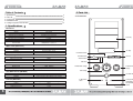
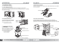
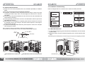
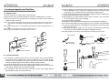
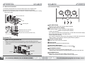
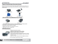
Notes
Installation Notes
English Version
1. Check the condition of the product and its components before installation. If there is a
problem with the product and/or its components, please contact the retailer for
replacement.
2. Keep this unit away from heat sources such as direct sunlight, as well as from water, oil,
and humidity. Place the unit on a flat, stable, and well-ventilated area.
3. Do not drop or subject the unit to excessive force.
4. Do not mix any contaminants with the coolant when filling. It may cause product failure or
corrosion.
5. Check the manual when connecting cables. Incorrect connections can lead to fire resulting
from short circuiting.
6. Check for leaks on the Water Blocks and Tubes before installation.
7. Preparing the necessary tools (Needle-Nose Pliers, Scissors) will ease the installation
process.
Operational Notes
1. Check to see if the DC cables are properly connected before use.
2. Avoid inserting any objects into the system while the power is ON. It may be harmful for the
user and product.
3. If the coolant is not circulating properly or if the pump’s flow rate becomes too low for other
reasons, the red LED will begin to flicker with an alarm sound. Immediately turn the system
OFF and contact the place of purchase.
4. Must use the provided coolant. Regularly check the amount of coolant and replenish as
needed (replacement cycle of the ZM-G300 coolant is 1 year).
5. If a leak is found, turn off the system immediately and contact the place of purchase.
6. Do not block the Air Ducts on either side of the product. This can lead to fan failure,
increased noise, or a decrease in product performance.
7. Make sure that the Water Pump is functioning properly.
Visit our website and watch the Z-Machine LQ1000 installation
video for an installation overview.
Disclaimer
Zalman Tech Co., Ltd. is not responsible for any damages due to external causes, including
but not limited to, improper use, problems with electrical power, accident, neglect, alteration,
repair, improper installation, or improper testing.
※ Please read this manual thoroughly before installation.
※ The specifications of this product and its components may change without prior notice to improve
performance.
1
2
Table of Contents
2. Parts List
1. Specifications
2. Parts List
3. Components
4. Installation Guide
5. Leakage Inspection and Test Run
3
4
6
7
13
2.1 Front View
1. Specifications
Enclosure
Dimensions (L x W x H)
Weight
Material
Motherboard Compatibility
PSU Compatibility
PCI/AGP Card Compatibility
Drive Bays
Front I/O Port
480mm X 220mm X 450mm
15kg (33lb)
Aluminum Alloy
Standard ATX / microATX
Standard ATX / ATX12V
Full Size
3.5" Bay x 5, 5.25" Bay x 4
USB Port x 2 , IEEE1394(Firewire) Port x 1
Headphones x 1, MIC x 1
5.25” Bay
Water Tank (Reservoir)
Dimensions (L x W x H)
Weight
Material
Coolant Capacity
125mm X 172mm X 26mm
800g
Aluminum Alloy, Acrylic
Max. 300cc
Water Pump
Power Consumption
Maximum Flow Rate
Maximum Lift
6W, DC 12V
300l/hr
1.8m
220(L) x 220(W) x 30(H) mm
2 Ball - Bearing
550rpm ± 10% ~ 850rpm ± 10%
3
I/O Port
SYSTEM LED
FAN SPEED Gauge
63(L) x 63(W) x 40(H) mm
160g
Cover (Aluminum Alloy), Base (Pure Copper)
Coolant (ZM-G300)
Material
Volume
Freezing Point
Replacement Cycle
POWER Button
FLOW RATE
Gauge
FND Gauge
CPU Water Block (ZM-WB5)
Dimensions (L x W x H)
Weight
Material
PC RESET Button
HDD LED
220mm Fan
Dimensions (L x W x H)
Bearing Type
Fan Speed (Min ~ Max)
3.5” Bay
VOLUME KNOB
Button
Propylene Glycol & Anti-Corrosion Agent
250cc
-9 ℃
1 Year
Cooling System
LED/RESET Button
AUTO/MANUAL
Button
4
3. Components
2.2 Side View
Water Tank (Reservoir)
Tool-Free Bolt
Reservoir Cap
(1) Enclosure
(5) Funnel
120mm Fan
(6) Silicone Tube (1m)
(2) CPU Water Block (ZM-WB5)
(7) 220mm LED Fan
Reservoir Window
(3) Jump Cable
(8) 220mm LED Fan Grill
(4) Anti-Corrosion Coolant (ZM-G300)
(9) User’s Manual
Radiator
220mm Fan Install Tap Hole
Left Door
Silicon Tube
Tube Nipple
Tool-Free HDD Bay
Water Pump
5
(10) Bolt Parts
Diagram
Part Name
Specifications
Qty.
Application
L Wrench
3mm
1
Assembly
Allen Screw
M4*8
4
Outer Chassis
Optional Fan Stand Off
M3*28*(+)3*(-3)
4
Optional Fan Install
M/B Stand Off
M3*10*(+)3*(-3)
12
M/B Installation
PSU Screws
PH #6-32*10
6
PSU Installation
ODD, M/B Screws
PWH, M3*5
24
ODD, M/B Installation
Fan Fixing Bolt
PWH, M3*10
4
220mm Fan Installation
Hand Bolt
P9*15.4
4
HDD Installation
6
4.4 Motherboard Installation
4. Installation Guide
Secure the motherboard to the enclosure, then, install components (CPU, VGA, RAM, etc.)
onto the motherboard.
4.1 Power Supply Installation
Unscrew the four Bolts (Bolt, FH M3x6) as shown in the diagram to open the Doors.
Place the PSU on the Power Bracket, and screw the four Bolts (Bolt, PHM #6-32*10 (Black))
from outside the enclosure.
Clip Support for Socket 775
Mother Board
4.5 3.5”/5.25” Drive Installation
4.2 Pump Bracket Removal
To prevent damage to the unit during
transport, the Pump Bracket is removed.
Note) The Pump Bracket can cause
unwanted noise if not removed.
(1) Remove the Bay Covers of the 3.5” (FDD) bay and the 5.25” (ODD) bays
(2) Insert the ODD into desired 5.25” bay, and fix it in place with the Tool Free Bolts.
(3) ODD Slot 3 & 4 and the FDD Slot require using Fixing Bolts (Bolt, M3x5) to secure drives.
Water Pump
Bracket
Water Pump
Slot 3 ODD
4.3 CPU Water Block(ZM-WB5)
Guide Install
Before installing the motherboard,
please refer to ZM-WB5’s manual for
correct socket installation procedures.
Note) Intel CPU users: please refer
to the CPU waterblock’s
manual for installation
Slot 4 ODD
FDD Slot
Water Block
Clip Support Fixing Bolt
Tool-Free Bolt
Clip Support for Socket 775
ODD Bay Cover
Back plate for Socket 775
FDD Bay Cover
ex) Intel Pentium 4 (Socket 775) installation
7
8
4.6 Hard Disk Drive Installation
4.7 Cable Connection
Button PCB
Improper connection of the Power LED and
HDD LED can lead to LED malfunction.
Please refer to your motherboard’s manual
before making cable connections.
HDD chassis
4.8 Front I/O Connection
Lock Bar
Certain motherboards have different configurations for the IEEE1394a, USB2.0, and audio
connectors from the one shown in the diagram below. Please refer to your motherboard’s
manual.
I/O Port PCB
(1) Open (raise to unlock) the HDD Lock Bar of the desired HDD Chassis Bay.
(2) Slide HDD into desired Bay and close (lower to lock) the HDD Lock Bar behind the HDD.
(3) To remove the HDD, open (roll up) the HDD Lock Bar above the HDD.
(4) For transportation, lower the HDD Lock Bar and secure with Hand Bolts as shown below.
Fixing Tap Hole
Hand Bolt
Lock Groove
Lock Bar
Note1) Excessive pressure may damage the HDD Lock Bars. Please take caution during HDD installation
and removal.
Note2) Reverse the procedure for removal.
Note) Improper connections of the IEEE1394 connector and/or USB2.0 connector to the motherboard
can result in irreversible damage so please refer to both the product and your motherboard’s
manual prior to installation.
9
10
4.9 Silicone Tube Connection
4.10 Installation Troubleshooting
(1) Please refer to the manual included with the CPU waterblock (ZM-WB5) for installation
guides.
(2) The user can add optional VGA and Northbridge waterblocks.
(3) Use Needle - Nose Pliers to loosen and pull back the Tube Clamp on the tip of the Tube
connecting the Water Pump’s outlet to the Tube Nipple, then disconnect the Tube from
Tube Nipple.
(4) Connect the tip of the disconnected Silicone Tube to the Inlet of the CPU Water Block and
secure with the Tube Clamp.
(5) Use the separately provided tube to connect the CPU Waterblock’s outlet and join with the
Tube Nipple from of step 3.
(6) After the Silicone Tube installation is completed, please check for tensile forces in the tube
by repeatedly opening and closing the side panel. Please adjust the Tube length to
prevent tension in the Tube.
(7) If optional VGA/Northbridge Water blocks are, please repeat the “tension test” and adjust
Tube the length as needed.
Refer to the diagram below as a reference for the coolant’s circulation path/ order.
Note 1) Please do not apply Thermal Grease or Pads when installing waterblocks.
Note 2) Please refer to each product's manual when installing VGA/Northbridge waterblocks.
Tube Clamp
4.11 Water Block Removal
(1) To allow adequate degassing, please disassemble the Waterblock’s from the motherboard
as shown below.
(2) Skipping procedure will prevent adequate degassing due to internal pressure within the
Tubes.
Note) Please place the Waterblock’s at or below the height of the pump for the degassing procedure.
Tube Nipple
With CPU Water block installed alone
VGA Water Block installed with CPU Water Block
VGA Water Block
CPU Water Block
11
12
5. Leakage Inspection and Test Run
5.1 Adding Coolant
(1) Remove the Reservoir Cap by turning counter-clockwise.
(2) Mix half 125cc of the provided coolant 250cc with 500cc of distilled water in a container.
(3) Secure the Funnel in the Pouring Hole and carefully pour coolant up to the Reservoir
Window’s “High Level” mark.
Note 1) Please prevent coolant spillage by carefully pouring with the provided Funnel. Coolant Level will
drop when the coolant begins circulating. please pour additional coolant up to the “High Leve”
mark.
Note 2) The provided coolant is a concentrated liquid. please dilute the coolant with distilled water in a 1:4
ratio.
Note 3) Read the warning label on the coolant’s container prior to use.
Note 4) Keep the LQ1000 and its components away from children.
(5) Check for leakage at each inlet/outlet. Leakage can lead to short-circuiting and/or damage
to the motherboard or other components. If leaking is discovered, turn OFF the power,
completely remove any leaked coolant, and reassemble the leaking section.
(6) Coolant Level will drop when the coolant begins circulating. Please pour additional coolant
up to the Reservoir Window's “High Level” mark.
(7) After degassing is complete, detach the PSU’s power connection. Use a coin-like object
to secure the Reservoir Cap to prevent leaking.
(8) Lay the LQ1000 on its right side
(9) Reinstall the Water Block that were removed from the motherboard for degassing.
(10) Connect the PSU’s Main Connector and the CPU 4-Pin Connector to the motherboard.
(11) To prevent coolant leakage the LQ1000 Must be set upright on its feet before proceeding
with the next step (12).
(12) After setting the LQ1000 upright on its feet, remove the Sealing Bolt from the Reservoir
Cap and secure the Sealing Bolt in the adjacent Sealing Bolt Tap Hole.
Note) Cable organization is necessary to prevent interference with tubes when the Left Door.
Black Wire
4-Pin Connector
Funnel
Main Connector
Green Wire
Reservoir Cap
Power Supply
4-Pin Connector
Motherboard Power
Connector
Jump Cable
Pouring Hole
High Level
High Level
Reservoir Window
5.2 Coolant Circulation
(1) To provide the necessary power (12V DC) for your Test Run and Leakage Inspection,
please disconnect the PSU’s Main Connector (20P/24P) and 4-Pin CPU ancillary
connector from the motherboard and use the provided Jump Cable to connect the Main
Connector’s (20P/24P) green wire terminal to a black wire ground terminal.
(2) Connect the Display PCB’s 4-Pin power connector and the PSU’s 4-Pin connector.
(3) When power is supplied, the front panel display/gauges will light up red and the Left Door’
Flow Indicator will light up blue with a spinning impeller.
(4) For discharging of gas and good coolant circulation, turn the Power Supply ON/OFF
approximately 3~7 times at 10 second intervals.
13
Sealing Bolt Tap Hole
Sealing Bolt
High Level
Reservoir Cap
14
5.3 220mm Fan Installation
5.4 Front Panel Display
(1) Install the provided 220mm Fan and Ffan Grill as shown in the diagram below.
(2) Connect the 220mm Fan’s 3-Pin Connector to the Black 3-Pin Connector.
(3) After the Fan is installed, please be cautious to prevent inference between or among
Tubes and/or cables.
220mm Fan Stand Off
Fan Grill
Fan Fixing Bolt
Fan Speed Gauge
- Display the 120mm Rear Fan’s rotation speed in real-time.
FND (Flexible Numeric Display)
120mm Rear Fan 3-Pin Connector
220mm Fan 3-Pin Connector
Black PCB 3-Pin Connector (for 220mm Fan)
Performance Tip!
- Temperature Display: Coolant Temperature (upper display),
Ambient Temperature (lower display)
- Coolant Level Sensing
If the coolant level drops below a threshold level, an alarm will sound and the display will
flicker. Please refill with coolant, if the display flickers.
- Coolant Temperature Sensing
If the coolant’s temperature reaches above 60°C(92 ), an alarm will sound and the FND
Display will flicker. If the flickering is observed, please check for problems.
Coolant Flow Rate Gauge
When not using the 220mm fan
- Displays the coolant’s flow rate in real time.
- Make sure the side panel is securely closed for a quiet computing environment.
- Sealing off the I/O cover and PCI Bracket (with tape etc) will optimize the cooler's
performance
Control Knob
- Controls the Fan Speed and Coolant Flow Rate.
Temperature Mode Button
- Sets the temperature display to Celsius(°C) or Fahrenheit( ).
AUTO/MANUAL Button
I/0 Cover
PCI Bracket
- AUTO Mode: Automat fan speed and coolant flow rate.
- MANUAL Mode: Allows the user to manually adjust fan speed and coolant flow rate.
LED/RESET Button
- LED On/Off: A short press turn the displays’ LED’s On & Off.
- RESET: A long press for at least 5 seconds resets the cooling system.
15
16
Zalman Computer Noise Prevention System
Stable performance and a noiseless liquid cooling system can both be achieved with the use
of Zalman’s Ultra Quiet Power Supply, VGA Water Block, Northbridge Water Block and Super
Thermal Grease.
Ultra Quiet Power Supply
VGA Water block
Northbridge Water Block
Super Thermal Grease
Dual Heatpipe Cooled Modular Power Supply
ZM850-HP
ZM1000-HP
Dual Heatpipes Installed for Maximum Cooling Performance and Ultra-Quiet Operation
Improved Power Factor & Reduced Harmonics through Active PFC
High Efficiency Design and 80 PLUS Certified
Supports ATX12V CPU 4-Pin and EPS12V CPU 8-Pin
Gold-Plated Terminals & 16AWG Wires
HTPC Enclosures
160XT-PLUS
Designed for High TDP Processors
Designed for High Performance Power Supplies
Designed for Optimal Graphic Card Performance
Designed to Maximize HDD and LCD Lifespan
The front panel DFSTN LCD provides user access to various
features such as the Graphic Equalizer, Volume, Power, HDD
Operation, Time etc
Sliding HDD and ODD Chassis provide easy installation and removal.
For more information, please visit our website.
17