1
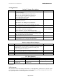
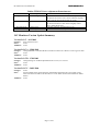
Industronics
Design, Application and Service of Electronics in Industry
DC Monitron User Manual
For Version D 3.17C
7 March, 2004
27 Wanganui Road Kirrawee NSW Australia 2232
Phone: (02) 9545 6181 Fax: +61 2 9545 6181 Mobile: 0419 267 889
Email: [email protected] WWW: http://www.industronics.biz
A division of D.H. Enterprises Pty Limited A.B.N. 72 087 000 995
Industronics
DC Monitron User Manual.doc
Overview
This manual covers the Monitron version that controls a DC Servomotor and contains a Baldor ‘TFM’
drive control. The Monitron is an upgrade for either an Impresstik Monitor or Unitron Control Box. The
entire front panel and control board is replaced providing a more reliable and fully featured controller. If
an older type incandescent label gap sensor was used this must be upgraded to a 24 volt fork type sensor.
Apart from this, it is simply a matter of plugging the upgraded box into the old position and learning the
new controls. All of the adjustments are made with three pushbuttons on the front panel. There is a two
line by twenty-character LCD display for viewing the settings. Settings can also be adjusted via a serial
port if this option is installed.
Menu Structure
InStep 2 Ver D 3.17
By Industronics
This is the opening screen. If Enter is pressed and held during this screen, the controller will display the
initialisation menu. Refer to the end of this section for details.
If Enter is not pressed the following menu is displayed after a ten second delay:
Level One Menus
Label Counter
0
The Label Counter is displayed here. This shows the total number of labels dispensed since turn on or the
last count reset. Pressing Enter will reset the label count. As at version 3.17 the count is lost when the
Monitron is powered down. Pressing the down arrow displays the following screen:
Air Blast Time
0
The Air Blast Time setting is displayed here. This menu sets the air blast time in milliseconds. The air
blast is for machines with an air box attachment. The air blast time occurs after the product sensor is
activated and before the label starts to move. On non-airbox machines this setting may also be used to
delay application of the label. Pressing the down arrow displays the following screen:
Motor Speed
0
The run speed of the DC servomotor is set here. 0 is zero speed and 255 is maximum speed. The
uppermost adjustment on the front of the TFM drive control card can be used to change the maximum
speed. Pressing the down arrow displays the following screen:
Labelling is
Enabled
Pressing Enter cycles between “Enabled” and “Disabled”. This menu is provided to allow for re-enabling
after an ignored fault of to disable so that the product sensor is ignored or the drive roller can be turned by
hand.
Level Two Menus
Pressing the down arrow rolls around to the “Label Counter” menu. Pressing Enter takes you to level two
menus and displays the following screen:
Page 2 of 11
Industronics
DC Monitron User Manual.doc
Level Two Menus
Manual Dispense
Press Enter to Start
Pressing Enter starts a labelling cycle. Pressing the down arrow displays the following screen:
Printer
Disabled
The Printer menu is shown here. Pressing Enter cycles between Disabled and Enabled. Use the “Option
Menu” to select the type of printer fitted and the “Option2 Menu” to select the type of printer fault signal.
Pressing the down arrow displays the following screen:
Missing Label Length
5
If a label is dispensed and a gap sensor input is not detected before the time set here the labeller will
disable, show “Labeller error” and turn on the Bussed Fault Output. A value of 0 allows infinite length, 1
= 0.07 sec, 2 = 0.14 sec, 3 = 0.28 sec, 4 = 0.56 sec, 5 = 1.12 sec, 6 = 2.25 sec, 7 = 4.5 sec and 8 = 9
seconds. Pressing the down arrow displays the following screen:
Brake On Time
100
The time that the servomotor brakes for is set here. The setting should be such that it is sufficiently long
enough to bring the web to a complete stop but not so long as to allow any speed drift to effect the
stopping position. Pressing the down arrow displays the following screen:
Library Functions
Pressing the down arrow displays the “Level Three Menus” selection screen further below. Pressing Enter
takes you into the Library sub-menu and displays the following screen:
Save to Library No.
0
This is the first menu in the library sub-menu. Pressing Enter allows you to select the library
number to save to with the arrow keys. After selecting, pressing Enter saves all of the data
from the current data memory and displays the “Library Functions” menu. (There is no
library number zero, it is provided to allow a way to “escape” without saving.) Pressing the
down arrow displays the following screen:
Read from Lib No.
0
This is the second menu in the library sub-menu. Pressing Enter allows you to select the
library number to read from. After selecting, pressing Enter reads the library and saves it to
the current data memory. If after pressing Enter, the “Library Functions” menu is not
displayed, the data in the selected menu was invalid. Select another library number or select
0 to escape from this menu. Pressing the down arrow displays the “Library Functions”
menu.
Page 3 of 11
Industronics
DC Monitron User Manual.doc
Level Three Menus
Pressing Enter takes you to level three menus and displays the “Force Brake” menu. Pressing the down
arrow displays the following screen:
Level One Menus
Pressing Enter takes you to level one menus and displays the “Label Counter” menu. Pressing the down
arrow displays the “Manual Dispense” menu.
Level Three Menus
Force Brake
Off
The brake can be forced on and off here. Forcing the brake on allows adjustment of zero speed via the
lowest adjustment on the front of the TFM drive control card. Irrespective of where this setting is left, it
will be corrected during the first dispense cycle. Pressing the down arrow displays the following screen:
Inputs:
PGDSPEJC
00000000
This is the third menu in level three. The input status is displayed here. A value of 1 indicates the input is
on, 0 is off. The letters above the value indicate what the input is used for.
P – Product Sensor
G – Gap Sensor
D – Disable Input (Fault In)
S – Servo OK
P – Printer OK
E – End of Reel Input
J – Jig In / Product Gate Input
C – Colour Sensor
The display is not live, pressing Enter updates the display.
Pressing the down arrow displays the following screen:
Outputs: XFABJSEC
00000000
The output status is displayed here. A value of 1 indicates the output is on, 0 is off. The letters above the
value indicate what the output is used for.
X – Spare
F – Fault Output
A – Air Assist Output
B – Air Blast Output
J – Jig Solenoid Output
S – Feedscrew Enable Output
E – Servo Enable / Stepper Boost Output
C – Coder (Printer) Output
The display is not live, pressing Enter updates the display.
Pressing the down arrow displays the following screen:
Page 4 of 11
Industronics
DC Monitron User Manual.doc
Options: GSGEC421
00000000
The option status is displayed here. A value of 1 indicates the option is on, 0 is off. The letters above the
value indicate what the input is used for.
G – Gate Signal Required
S – Servo Mode (Not Stepper). On for speed compensation and servo enable. Off for stepper drives.
G – SIG drive compensation. Must select servo mode above as well!
E – Enable at Power On
C – Moving Type Coder e.g. inkjet (0 = Stationary Type e.g. stamping hot foil)
421 – Serial Address Select (Set bits to total to desired address, all off = 8)
Pressing Enter takes you into edit mode. The display counts up and down in binary.
Pressing the down arrow displays the following screen:
Option2: ????BSPF
00000000
The second option status menu is displayed here. A value of 1 indicates the option is on, 0 is off. The
letters above the value indicate what the input is used for.
B – Stepper Boost. When on changes the servo enable output function to a stepper drive boost.
S – Servo OK input polarity. When on here the Servo OK input is off = OK. Can be used when no servo
ok signal is available. (i.e. in a Monitron)
P – Printer Fault polarity. When the printer is enabled in level 2 the Printer Fault input becomes active.
The level that causes labelling to be stopped is entered here. 0 = on, 1 = off.
F – Fixed Pull Mode. This is different from InStep I fixed pull mode, it is triggered by the product
scanner.
AnlgOut: ?GIO?VCF
Options: 00000000
The analogue output option status is displayed here. The settings are only relevant if the Analogue Output
Option Board has been fitted. A value of 1 indicates the option is on, 0 is off. The letters above the value
indicate what the input is used for.
G – Guarding closed input monitored.
I – Infeed Low Sensor monitored.
O – Outfeed High Sensor monitored.
? – Spare.
V – Vacuum Belt Speed Adjustment enabled.
C – Conveyor Speed Adjustment enabled.
F – Feedscrew Speed Adjustment enabled. (Used for “Motor Speed” on a DC Monitron)
When the speed adjustments are disabled they are shutdown and the menu screens removed.
Refer to the Analogue Output Option Board manual for further details.
Pressing Enter takes you into edit mode. The display counts up and down in binary.
Pressing the down arrow displays the following screen:
Level Two Menus
Pressing Enter takes you to level two menus and displays the “Manual Dispense” menu. Pressing the down
arrow displays the following screen:
Level One Menus
Pressing Enter takes you to level one menus and displays the “Label Counter” menu. Pressing the down
arrow rolls around and displays the Acceleration menu.
Page 5 of 11
Industronics
DC Monitron User Manual.doc
Fault Screens
The following screens appear when the fault occurs. If the fault is rectified the screen can be cleared and
the labeller re-enabled by presssing Enter. If you would like to review your settings without resetting, the
first press of either arrow key will bring back the menu that was present before the fault occurred. You can
then move around the menus as usual. Afterwards, you can re-enable the labelling by using the “Labelling
Enable” menu in Level 1.
Labeller Error!
Press Enter to Reset
This screen indicates that the motor has moved too far in its search for the gap sensor activation. It is
usually caused by a wrongly setup gap sensor or slipping drive rollers. It can always be reset immediately.
Refer to the “Missing Label Length” menu in level two for adjustment.
Printer Error!
Press Enter to Reset
Whenever the printer is enabled the printer fault signal is also enabled. The sense of the input is controlled
by a bit in option port 2 or by the ‘D’ command. If no printer fault signal is available it should be set to off
= OK (default). The fault signal must be removed to reset.
External Fault!
Press Enter to Reset
This screen appears when the Fault In input is activated. This input is usually tied together with all of the
other Fault In/Fault Outs on the machine so that a fault on one label head will disable all heads.
Stepper Drive Error!
Press Enter to Reset
This screen appears when the connected stepper drive has indicated a fault. You usually must power down
the stepper drive to reset the fault. If the fault occurs often it will be necessary to open the enclosure to
check the fault code indicated on the front of the stepper drive. Refer to the stepper drive manual for the
fault codes meaning and its remedy. It is usually caused by a web jam up.
End of Label Reel!
Press Enter to Reset
This screen appears when the sensor connected to the End of Reel input is on. It is usually a sensor setup
to detect a low quantity of labels on the unwind reel.
Other fault screens may appear depending on the option card fitted and which functions are enabled.
Initialisation Menu
This menu can only be entered during power up. It will automatically appear if the controller detects
invalid data in the current data memory or it can be forced to appear if Enter is pressed and held during
the initial screen that displays the version number information. It will appear as either of the two following
screens:
Enter Pressed
Use ^ to make choice
or
EEPROM Data Invalid!
Use ^ to make choice
If the up arrow is pressed, the following screen will appear:
Enter Pressed
Erase Libraries
This is the first choice in the initialisation menus. Pressing Enter causes all of the Library data to be erased
then the first initialisation menu is shown again. Pressing the up arrow causes the next menu to be
displayed as follows:
Page 6 of 11
Industronics
DC Monitron User Manual.doc
Enter Pressed
Reinitialise?
This is the second choice in the initialisation menus. Pressing Enter causes all of the current data to be
reset to default values and then display the first menu in level one. Because of this, if you want to erase
libraries and reinitialise you must erase libraries first. Pressing the up arrow causes the next menu to be
displayed as follows:
Enter Pressed
Do Nothing
This is the third choice in the initialisation menus. Pressing Enter simply displays the first menu in level
one and as the menu suggests, does nothing. If the entry into the initialisation menus was caused by invalid
data you can’t use this option, but must select reinitialise. Pressing the up arrow causes the first
initialisation menu to be redisplayed.
Inputs
All inputs are selectable for NPN (1 to 2) or PNP (2 to 3) input devices. The function of
each input follows.
PRODSENS - Product Sensor
This input initiates the labelling sequence. It starts with a transition from off to on of this
input. See jumper J7 for input polarity selection. Terminal 1 on a Monitron.
GAPSENS - Gap Sensor
This is the registration input. It is normally connected to a fork sensor that detects the gap
between the labels on the backing paper. The label advance starts counting with an off to on
transition of this input. See jumper J8 for input polarity selection. Terminal 2 on a
Monitron.
ENC - Master Encoder
This is where the encoder for the product speed is connected. The encoder is usually
coupled to the conveyor or vacuum belt of the machine. See jumper J12 and J13 for input
polarity selection and J11 for voltage. The pulses per rev of the encoder and its gearing to
the conveyor / belt should be selected so that the rate is the same as the step rate of the
motor. It is best to be on the low side of one to one if this cannot be achieved. The encoder
should have an open collector 5 or 24VDC output. Terminal 16 on an ex Unitron.
IN1 – Colour Sensor (Product Sensor 2)
This input only functions in Orientation Mode. It triggers the labelling cycle just as the
normal product scanner does however only after the orient part of the cycle is complete. See
jumper J1 for input polarity selection. Terminal 4 on a Monitor adapter boards TB1.
IN2 – Jig In Sensor/Product Gate
This input is usually a proximity detector mounted on the orientation jig to indicate when
the jig is closed. It initiates the spin up delay in orient jig mode. If option port jumper J31 is
installed this input becomes the product sensor gate input. In this mode this input must be
on before a product detection will start the dispense cycle. See jumper J2 for input polarity
selection. Terminal 5 on a Monitor adapter boards TB1.
IN3 – End of Reel
This input is usually connected to a sensor that detects a low level of labels on the unwind
reel. When this input is on labelling is disabled and the End of Reel screen is displayed. See
jumper J3 for input polarity selection. Terminal 6 on a Monitor adapter boards TB1.
Page 7 of 11
Industronics
DC Monitron User Manual.doc
IN4 – Printer OK
This input is connected to the printer OK/fault output of the printer controlled by the InStep
module. When the printer is enabled by the Coder Delay (D) command with an odd value
this input must be on otherwise the InStep is disabled and the bussed fault output is turned
on. If an even value is used in D the input must be off for printer OK. See jumper J4 for
input polarity selection. Pin 2 of CON3 on a Monitor adapter Board.
IN5 – Drive OK
Polarity controlled by a bit in Option 2 menu. When signal active labelling is disabled and
the drive error menu is displayed. Terminal 7 on a Monitor adapter boards TB1.
IN6 - Disable (Bussed Fault In)
This input disables the labelling on a transition from off to on. Even if the input is left on
the unit may be re-enabled via the “E1” command. See J6 for input polarity selection.
Terminal 8 on a Monitor adapter boards TB1
Outputs
All outputs are selectable for NPN or PNP however they must all be one or the other.
Selection is made by changing IC9. For NPN use ULN2803A, for PNP use UDN2981A.
Jumpers J9 and J10 must be set to suit. In a Monitron, the IC is PNP but the main outputs
have slave transistors that provide a NPN output.
STEP – Step Signal
This output is used to drive the pulse input of the stepper or servo drive. Connected
internally. Unused in a DC Monitron.
OUT1 – Coder
This output is the start trigger for a date coder etc. Option Menu selects whether the coder is
of the type that prints while the web is stationary (e.g. hot stamp) or moving (e.g. ink jet).
Terminal 6 on a Monitron.
OUT2 – Servo Enable/Stepper Boost
This output is connected internally to the stepper drive to control the boost function on the
D550. On a DC Monitron it is the DC Servo Enable signal.
OUT3 – Feedscrew Enable/Servotron OK Output
This output is provided to enable the feedscrew. It is on whenever there are no faults and no
level pauses from the high outfeed and low infeed sensors. This output becomes an OK
output whenever the level control are not enabled in the Analogue setup. It is on whenever
there are no faults present. The analog output option board is required for the level sensor
inputs. Terminal 9 on a Monitor adapter boards TB1.
OUT4 – Jig Solenoid
This output controls the solenoid that closes the orient jig. Pin 2 of CON4 on a Monitor
adapter board.
OUT5 – Air Blast
When an air blast time is entered in the menu or with the K command, this output is turned
on at the end of the product delay and before the servo starts to move. Terminal 11 on a
Monitron.
OUT6 – Air Assist
This output is turned on at the start of the servo moving and off at the beginning of
deceleration. Terminal 9 on a Monitron.
Page 8 of 11
Industronics
DC Monitron User Manual.doc
OUT7 – Bussed Fault Out
This output is turned on when there is a labeller fault or a printer fault. Terminal 10 on a
Monitor adapter boards TB1.
Connectors
Tuchel 16 way Rear Panel Connector
Connector
Pin Number
1
2
3
4
5
6
7
8
9
10
11
12
13
14
15
16
Signal
Product Scanner
Gap Scanner
Ground
No Connection
Ground
Printer
24 Volts
No Connection
Air Assist
24 Volts for above
Air Blast
24 Volts for above
No Connection
No Connection
No Connection
Master Encoder
Machine
Terminal
3
4
2
6
5
7
1
9
8
11
10
16
Comment
Must be new 24 volt type
5.5 volts for old gap scanner not supported
Use for scanner power
24V in a Unitron (Boost in some DC Monitor’s)
Special unregulated voltage in an ex Monitor
Special unregulated voltage in an ex Monitor
Only wired to adapter board in an ex Unitron
DC Motor Rear Panel Connector
Pin Number
A
B
C
D
E
F
G
H
Signal
Tachometer – Green
Tachometer – Yellow
N.C.
N.C.
Armature – Blue
Armature – Red
N.C.
Earth – Green/Yellow
Comment
TFM Pin 14c and 16c
TFM Pin 12c
TFM Pin 20a and 20c
TFM Pin 22a and 22c
Adapter Board Terminal Strip TB1
Terminal Number
Signal
1
Spare 1
2
Spare 2
3
Spare 3
4
IN 1
5
IN 2
6
IN 3
7
IN 5
8
IN 6
9
OUT 3
10
OUT 7
11
ENC
12
Flap Adapt
13
+24Vdc
14
0V
Note: Terminal strip not normally fitted.
Description
DC Drive analogue command signal
Depends on Option Board (RS-232 RxD)
Depends on Option Board
Colour Sensor (Product Sensor 2)
Jig In Sensor / Product Gate
Fixed Pull
Servo OK
Disable
Missing Label
Fault
Master Encoder
Flap Adapter (Driven by OUT4)
Page 9 of 11
Industronics
DC Monitron User Manual.doc
Configuration
InStep II Jumper Descriptions
Jumper
J1 to J8
J9 and J10
J11
J12 and J13
J14 to J24
J25
J26
Description
These three point jumpers select the polarity of the signal required
to operate the inputs.
Jump 1 to 2 for sinking (NPN) type input devices.
Jump 2 to 3 for sourcing (PNP) type input devices.
J1 to J6 correspond to input 1 to 6 respectively.
J7 is for the product sensor input.
J8 is for the label sensor input.
These jumpers are set to match the type of output driver IC
installed in position IC9.
Jump both 1 to 2 for NPN type IC (ULN2803A)
Jump both 2 to 3 for PNP type IC (UDN2981A)
Note: jumpers must be set correctly or damage will result!
Install Jumper 11 when 5 volt encoder is used. J12/13 must be in
PNP configuration when this jumper is installed!
These jumpers are set to match the polarity of the output of the
master encoder connected to terminal 11.
Jumper J12 and J13 1 to 2 for NPN output encoders.
Jumper J13 2 to 3 and J12/1 to J13/1 for PNP output encoders.
These jumpers set the master encoder divisor. J14 is divide by
one, J14 is divide by 2 through to J24 which is divide by 1024.
Only one jumper in this set to be installed!
Selects the function on pin 28 on P1. Refer to option manual.
Selects whether to bypass the encoders optocoupler. 1 to 2 is to
use optocoupler, 2 to 3 is to bypass the optocoupler.
Default
1 to 2 jumpered
2 to 3 jumpered
Not fitted
J12, 1 to 2 jumpered
J13, 1 to 2 jumpered
J14 installed
1 to 2 jumpered
1 to 2 jumpered
Monitor Adapter Board Jumpers
Jumper
A,B
CON3
CON4
CON5
Description
Jump A to provide NPN output on CON2 pin 16 for stepper boost
signal. Jump B to provide PNP 14 volt output on CON2 pin 16 for
TFM enable, 14 volts must be brought in on CON2 pin 8.
Only one jumper to be installed!
IN4. Provided to copy original PCB. Not sure what it was used
for. Possibly gap edge select, not supported in software.
OUT4. Flap Adapter Output. Has BD681 NPN driver.
OUT6. Air Assist Output. Often used to drive label counter.
Default
B jumpered
N/A
N/A
N/A
DC Drive Jumpers
(Located just under adjustment potentiometers)
Jumper
Near Edge of Board
Away from Edge
Correct Position
Top
Current Mode
Velocity Mode
Away from Edge
Bottom
It limit not active.
It limit active.
Near Edge
I peak = 6A
I peak = 12A
Note: On some drives the incorrect pin has been cut off and the link made with a solder bridge
underneath!
LCD Contrast
Near the bottom corner of the InStep II PCB there is a small adjustment potentiometer to adjust the liquid
crystal displays contrast. The display contrast is directly affected by the ambient temperature and as such
may require adjustment in extreme temperature environments.
Page 10 of 11
Industronics
DC Monitron User Manual.doc
Baldor TFM DC Drive Adjustment Potentiometers
Number
1 – Uppermost
Purpose
Tacho Voltage Scaling
2 – Second top
Velocity Loop Gain
3 – Second bottom
4 - Lowest
Current Limit
Offset Adjust
How to Adjust
Adjust to set the maximum desired motor speed when
the speed is set to 255. CW is slower. Beware of going
to far CCW as uncontrolled speed can occur!
Turn full CCW, then turn CW until very soft “grumble”
can be heard in motor. Then back of slightly until it
stops. (Often about 25%)
Turn full clockwise for maximum current.
With “Force Brake” ON, adjust for no drift.
DC Monitron Version Update Summary
Version D 3.17 - 6/12/2002
Changes:
Fixes:
Additions:
First released version.
None.
None.
Version D 3.17A - 25/08/2003
Changes:
Fixes:
Additions:
Changed default re-initialise Brake On Time from 200 to 50. Which is a more typical value.
None.
None.
Version D 3.17B - 17/09/2003
Changes:
Fixes:
Additions:
Changed range of Air Blast adjustment from 0 to 255, to 0 to 8191.
None.
None.
Version D 3.17C - 26/02/2004
Changes:
Fixes:
Additions:
None.
Fixed problem where if man dispense pushed while dispensing the cycle would re-start.
This is the same fix made to the Servotron at 3.22C. Refer to Servotron manual for further
details.
None.
Page 11 of 11