1
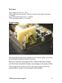
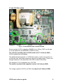
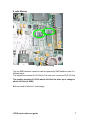
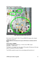
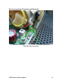
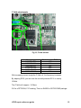
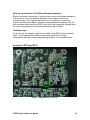
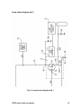
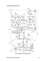
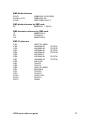
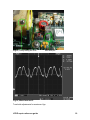
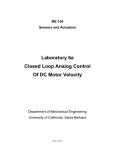
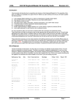
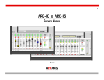
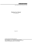
EFRATOM LPRO-101
Repair reference guide
By Fred de Vries, PE1FBO, 2008
Revision 2, August 2008, © PE1FBO
LPRO repair reference guide
1
Contents
Brief specs .....................................................................................................4
Rubidium lamp...............................................................................................4
Temperature controlled assemblies...............................................................5
17 and 14 Volts section .................................................................................6
5 volts filtering................................................................................................7
VCO and input protection diodes ...................................................................8
VCO section (20MHz)...................................................................................8
Lamp exciter diagram ....................................................................................9
Rb cell connections (SRD and C-field) ........................................................10
SRD Bias (Step Recovery Diode) ................................................................10
Rb cell connections (Thermistor and Photocell)...........................................11
C field adjustments ......................................................................................12
Possible faults on the unit. ...........................................................................13
Note on replacement of the Rb cell heater transistors .................................14
Tantalum caps .............................................................................................14
Location of R705 and R731 .........................................................................14
Lamp heater diagram sub 1 .........................................................................15
Lamp heater diagram sub 2 .........................................................................16
SMD diode reference...................................................................................17
SMD diode reference by SMD code ............................................................17
SMD transistor reference by SMD code ......................................................17
SMD IC reference ........................................................................................17
Tuning the unit .............................................................................................18
Efratom Rubidium synthesizer schema .......................................................20
Hyperfine resonance frequencies according to NIST...................................20
LPRO repair reference guide
2
Fig 1, Connections
LPRO repair reference guide
3
Brief specs
Input voltage 24 V DC. (19 .. 32V)
Input current when cold is about 1.25 Amp, when the lamp ignites it becomes
1.19 Amps.
Input current when warm is 0.35 .. 0.45 Amp
Time to lock when cold is 3 to 5 minutes
Rubidium lamp
Fig 2, Rubidium lamp
When the rubidium lamp section reaches 40 to 60° Celcius it ignites, you will see
the purple light coming from the back of the lamp.
Mind you, that when stray light (50Hz or 60Hz) enters the rubidium
cell, the whole unit starts to behave very strange, so be aware of this!
Lamp voltage (pin 5) can be as low as 3 Volts, below 3 volts an atomic lock
becomes difficult. Healthy units are ranging from 6 to 9 Volts.
LPRO repair reference guide
4
Temperature controlled assemblies
IRFU220
MJE802
IRFU220
Fig 3, Temperature controlled assembly
The Rubidium lamp housing is about 101° Celcius
The Rubidium cell is about 71° Celcius
The official temperatures (according to the manual) are 110° C for the lamp, and
79° C for the Rb cell.
The housing of the heated assemblies measures lower. Both samples had this. It
is also depending where you measure the temperature.
The base plate needs to be mounted on a heat sink to prevent loss of lock
and thermal runaway of the internal electronics.
As a test, you can operate the unit without heat-sink for about half an hour to
check if the electronics work reliable at higher ambient temperatures.
The TO202 heater transistor is a MJE802 (NPN darlington, 4A, 40Watt), this can
be replaced with an BD679 or BD681.
The TO251 transistors on the lamp and Rb-cell are IRFU220 MOSFETS,
4.6A/200V, 40 Watt. They can be replaced with an IRFU420 or STD3NB30
The Rb lamp exciter transistor is an MRF160, it’s a MOSFET from Motorola.
Ft 500 Mhz, 4W, 28 volts. A possible substitute could be the PD57006 from ST
LPRO repair reference guide
5
17 and 14 Volts section
Ceramic C
2N6490
4u7/35V
7805
Fig 4, 17 Volts section and 14 Volts section
Power transistor Q106 is originally a 2N6490, it is a 15Amp, PNP, low hfe type.
It can be replaced by an MJE2955T or BD912 if faulty.
The collector (mounting tab) of Q106 should be at 17.0 Volts (to GND)
Q106 is isolated from the chassis.
The additional black capacitor is 1uF/50Volts ceramic. I had to remove the one
on the back side, which was suspected to be short at higher temps. There is not
enough clearance on the back side of the PCB to have it fitted there.
The capacitor C116 is a tantalum one, 4.7uF/35V
The positive terminal of this capacitor is about 14.4 Volts (to GND)
The voltage regulator VR102 is an 7805, it’s output is at 5 Volts (to GND)
LPRO repair reference guide
6
5 volts filtering
Fig 5, 5 Volts filtering
The two SMD tantalum capacitors can be replaced by SMD tantalum ones of a
different value.
The original ones where 68 uF/16Volts. The new ones I used are 33uF/16 Volts.
The positive terminal of C419 is about 4.6 Volts, the other cap’s voltage is
about 4.4 Volts (to GND)
Both are used to filter the 5 Volts supply.
LPRO repair reference guide
7
VCO and input protection diodes
Fig 6, input protection diodes and VCO
Both diodes CR101 and CR 106 (F101) are SMBYW02 diodes, with a forward
voltage drop of 650 mV.
Both anodes are connected to the input of 24 Volts, the cathode is 23.35
Volts.
VCO section (20MHz)
Oscillator VCO range is rather big +/- 150 Hz for the 10Mhz output.
9.999 850 .. 10.000 180 Hz
Total time for a complete scan takes about 105 seconds. (60s ramp up, 45s ramp
down) The internal VCO works on 20MHz.
The 20 MHz crystal is housed in the round package with heat-sink on it.
LPRO repair reference guide
8
Lamp exciter diagram
Fig 7, Diagram of Rb lamp exciter
LPRO repair reference guide
9
Rb cell connections (SRD and C-field)
C-field coil connection
RF to cavity
Fig 8, Rb cell connections
SRD bias pot
SRD Bias (Step Recovery Diode)
The SRD bias potentiometer is typical set between 1.5 and 4 kOhms
If you disconnect the yellow coax cable you can measure the SRD forward
voltage drop of 0.7 Volts (center to shield).
LPRO repair reference guide
10
Rb cell connections (Thermistor and Photocell)
Thermistor connection
Photocell connection
Fig 9, Rb cell connections
LPRO repair reference guide
11
C field adjustments
Q10, PZT2222
R126
R116
Fig 10, C field resistor
Frequency
9.999.999.908
9.999.999.964
9.999.999.976
10.000.000.002
10.000.000.050
10.000.000.165
Resistor value R126
>100k
6k2
5k2
4k2
3k2
2k2
With increasing current trough the C field coil, the frequency increases.
By adapting R126, you can tune the unit with potmeter R116 to exactly
10 MHz
The C field coil is approx. 18 Ohms
Q10 is a PZT2222A, P1F marking, This is a 2N2222 in SOT223 SMD package.
LPRO repair reference guide
12
Possible faults on the unit.
Quote from Antonio, I8IOV
Before inspecting the lamp, I suggest the following checks:
-Check that the lamp housing gets VERY hot in about 1 minute (100°C).
-Check that the physics unit (on the other side of the foam) gets hot too (70°C).
-Check the presence of the RF field.
You could use a counter. Using a link of one turn of wire, check if you can read a
frequency of about 70 (or 140, second harmonic) MHz approaching the link to the
MRF160 power mosfet (if you read 60 MHz you are picking up the field of the
physics unit, not the field for lamp, then orient better the link). If you don't see the
signal, check the transistor on board. In one case I've found it shorted. If the
transistor seems OK, check resistors in the vicinity, even on the upper side of the
board. In one case I've found R705 (bottom, 100K) interrupted. It should read
(onboard) about 82K.
If the lamp assembly doesn't heat, check R731 (bottom of PCB)
In one case I had a faulty lamp. It can be inspected quite easily. Unlock the
hexagonal nut and unscrew the lamp, taking note of how much it protruded from
the assembly. Don't touch the lamp with fingers. A good lamp has a delicately
brownish glass, a lamp which leaked has transparent glass with some small
white pigments.
It you tried turning the lamp assembly trimmer in order to increase lamp volt, you
could have "forced" it causing the rotation of its hot (not ground) lead and
possible short on the coil inside the lamp assembly.
I would say all 100k resistors of this size on the board are suspect. They
are of the 0603 SMD size, and marked with 104 (The smallest parts on the
board)
If there is a problem with the heating of the Rb cell, check if the emitter of the
MJE802 is at 12 volts. This is about half the supply voltage, and follows the input
voltage. The voltage over the current sense resistors (backside) is about 300mV.
This is when the Rb cell is cold. There are 3 1.2Ohm resistors in parallel.
Current is 850 mA. Voltage on the gate of the IRFU220 when stabilised is about
4.4 volts, on the source it is 70 mV. Drain voltage is 12 Volts.
If there is a problem with the lamp heater, you could check if the voltage over the
2 Ohms resistor (backside) is about 0.4 Volts, this corresponds to 200mA.
LPRO repair reference guide
13
Note on replacement of the Rb cell heater transistors
Efratom has used a fusing kind of isolation pad to mount both heater transistors.
This results in a very low thermal resistance from transistor case to the
aluminium base. If you replace the transistors it is important to restore the
original low thermal resistance. With an increased thermal resistance, the lock
time increases as well and the MTBF of the unit is also negatively affected since
the junction temperature of both heater transistors will be higher.
Tantalum caps
On an old unit, the tantalum caps have possibly a high ESR or are completely
open. I would replace them with new ones since the units run at high
temperatures and this has an accelerated aging effect on the tantalum caps.
Location of R705 and R731
Fig 11, Location of R705, R731
LPRO repair reference guide
14
Lamp heater diagram sub 1
Fig 12, Lamp heater diagram sub 1
LPRO repair reference guide
15
Lamp heater diagram sub 2
Fig 13, Lamp heater diagram sub 2
LPRO repair reference guide
16
SMD diode reference
CR101
CR106 or F101
CR102
SMBYW02-100 (BYW02)
SMBYW02-100
SMD CODE ER10 ??
SMD diode reference by SMD code
5D
MMBD914
(1N914)
SMD transistor reference by SMD code
1P
P1F
1JA
MMBT2222 A
PZT2222 A
MMBT2369 A
SMD IC reference
U101
U102
U103
U201
U202
U203
U204
U301
U302
U401
U402
U403
U501
U701
U702
VR101
VR103
VR701
LMC7101 AIM5X
LMC6482 IM
LMC6482 IM
LMC6484 IM
LMC6484 IM
MC14053 B
LMC6484 IM
LMC6484 IM
LM615 IM
74AC08
74AC74
LMC7101 AIM5X
MAX709 M
TLC2272
TLC2272
LP2951 CM
REF02 C
LM285
LPRO repair reference guide
(TLC272)
(TLC272)
(TLC274)
(TLC274)
(TLC274)
(TLC274)
17
Tuning the unit
Once you have a locked unit you can tune the SRD bias and the 6.8 GHz cavity.
Allow the unit to warm-up for 10 minutes. You can only do this after a lock has
been established. If you don’t have a lock, you probably make things worse by
adjusting the settings on the unit.
Fig 14, Test point J5, corner pin
LPRO repair reference guide
18
Fig 15, Cavity tuning 6.8 GHz
SRD bias pot
Fig 16, Wave form on J5
Tune both adjustments for maximum Vpp
LPRO repair reference guide
19
Efratom Rubidium synthesizer schema
A part)
10 MHz * 6 = 60 MHz
114 * 60 MHz = 6.840 GHz
B part)
10 MHz / 2 = 5 MHz
5 MHz / 16 = 0.3125 MHz
5 MHz XOR 0.3125 MHz = 5.3125 MHz
A and B are mixed, one of the components is
6.840 - 0.0053125 = 6.834 687 500 GHz
Hyperfine resonance frequencies according to NIST
Rubidium = 6.834 682 608 GHz
Hydrogen = 1.420 405 752 GHz
Caesium = 9.192 631 770 GHz
Difference of frequency (NIST measure and Efratom synth.) is due to buffer gas
in the Rb cell, that has a positive offset on the resonance frequency
LPRO repair reference guide
20