1
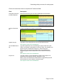
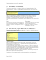
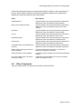
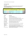
[Insert name]
newsletter
MONTH YEAR
CALCULATING SAFETY
OUTCOMES FOR ROAD
PROJECTS
User Manual
MAY 2012
Calculating safety outcomes for road projects
Page 2 of 20
Calculating safety outcomes for road projects
Contents
1
2
Introduction .............................................................................................. 4
1.1
Background.............................................................................................................. 4
1.2
Overview.................................................................................................................. 4
1.3
When is the Worksheet required? ........................................................................... 5
1.4
How the Safety Outcomes Worksheet functions ..................................................... 5
Using the Worksheet ............................................................................... 6
2.1
Introduction .............................................................................................................. 6
2.2
Entering the data ..................................................................................................... 6
2.3
Project Data ............................................................................................................. 7
2.4
Contact .................................................................................................................... 8
2.5
Location Data........................................................................................................... 8
2.6
Treatments............................................................................................................. 10
2.7
Road Safety Considerations.................................................................................. 12
2.8
How does this project address the key risk factors? ............................................. 12
2.9
Other Comments ................................................................................................... 13
2.10
Crash data ............................................................................................................. 14
3
Output ..................................................................................................... 15
4
Combining BCRs from separate Worksheets...................................... 16
5
Non-symmetrical treatments................................................................. 17
6
5.1
Shoulder treatments (Treatments 64 to 69) .......................................................... 17
5.2
Roadside safety barrier treatments (Treatments 85 to 88).................................... 17
5.3
Clearzone treatments (Treatments 90 to 92) ........................................................ 18
5.4
Examples ............................................................................................................... 18
CrashLink report .................................................................................... 20
6.1
Introduction ............................................................................................................ 20
6.2
CBA01-Crash History report.................................................................................. 20
Page 3 of 20
Calculating safety outcomes for road projects
1 Introduction
1.1
Background
Under the principle of mainstreaming road safety in the RMS, any business area that
can influence road safety outcomes has accountability for road safety. Road safety
accountability is not limited to road safety managers.
Assessments of the likely road safety outcomes of proposed projects can assist project
proponents to address road safety accountabilities. The preparation of road safety
impact statements ensures that the assessment process is addressed and the impact
statement provides information for decision-making. The process of assessing impacts
will result in an improvement to road safety if the resulting information is considered in
the selection of projects and decisions about works to be included.
1.2
Overview
A Microsoft Excel Worksheet, the Safety Outcomes Worksheet, has been designed to
perform the required calculations and provide an estimate of the safety impact of
proposed road projects.
This document is intended to provide instructions for using the Worksheet, shown
below.
Page 4 of 20
Calculating safety outcomes for road projects
1.3
When is the Worksheet required?
The Safety Outcomes Worksheet is required for all proposed road work projects except
major projects, as described below.
For some projects it may be necessary to prepare more than one Worksheet. For
example, if the speed limit changes along the length of the project site, a separate
worksheet may be needed for each speed limit. However, if the speed limit changes,
but stays within one of the defined ranges, a separate sheet is not necessary. The
three defined ranges are: ≤ 60km/h, 70km/h or 80km/h, and ≥ 90km/h. If the speed
limit changes, but stays within one of these ranges, there is no need to prepare a
separate sheet.
Major projects
This assessment method is not intended for application to major projects, where the
road is replaced or completely altered.
As the methods of assessing these projects have not yet been reviewed, please
continue using current methods for major projects.
1.4
How the Safety Outcomes Worksheet functions
Follow the instruction below to enter the data. The Worksheet then performs the
applicable calculations and provides information about the safety implications of the
proposed project.
You do not need to be familiar with the details of the calculations but some appreciation
of the method will assist you in understanding the process and the results. A brief
explanation is provided below.
Achieving safer roads means preventing fatalities and serious injuries. The method
used by the Worksheet estimates the number of likely crashes at the site with a
weighting for crashes that are likely to be more severe.
The likely severity of future crashes at the site is estimated from the characteristics of
the crashes that have occurred there in the past. Important characteristics that are
taken into account include crash type, the speed limit, the time of day of the crash and
the part of the state in which it occurred.
The proposed work is described in terms of the treatment type or a set of treatment
types. Each treatment type is associated with an expected proportional reduction in the
likelihood or severity of particular types of crashes. (Treatment types are listed in the
Excel Workbook, in the Reductions Worksheet.)
The method used by the Worksheet compares the expected number of fatalities,
serious injuries, other injuries and non-injury crashes in the future, with and without the
proposed work.
The comparison is then used to estimate the safety benefits of the work.
Page 5 of 20
Calculating safety outcomes for road projects
2 Using the Worksheet
2.1
Introduction
Follow the instructions below to enter the data under the following headings:
•
Project data
•
Contact
•
Location data
•
Treatments
•
Road safety considerations
•
Other comments
•
Crash data
2.2
Entering the data
For some data fields a drop-down list is provided while in others you are required to
enter the data.
Selecting data from a drop-down list
In a field where a drop-down list is provided it is essential to use it. Select the required
data from the list, as shown in the following example.
The input provided by fields with drop-down lists is used for calculations. Therefore the
data must be in a format that can be recognised by the Worksheet. Data entered in any
other format is not recognised by the Worksheet.
If you type data in the wrong format in a field with a drop-down list, an error message is
displayed, as shown below.
Typing data
In some fields you are required to enter the data. Type the data for these fields.
Page 6 of 20
Calculating safety outcomes for road projects
2.3
Project Data
The Project Data fields, shown below, identify the project, and provide basic project
information about it.
Follow these instructions to enter the Project Data.
Field
Description
Program Position
For RMS projects only, type the program position.
(for RMS internal use only)
Program Description
For RMS projects only, type a description of the program.
(for RMS internal use only)
Project Number
For RMS projects only, type the project number.
(for RMS internal use only)
Project Description
(for RMS internal use only)
For RMS projects only, type a brief description of the project including
sufficient information to explain the proposed work.
Total Capital Cost ($)
This field is automatically completed.
This input is used in the calculations.
Total Annual
Maintenance Cost ($)
This field is automatically completed.
There may not be a maintenance cost for the work. For example, the
project may be a maintenance project or it may be a short life project.
Suggested project lives and maintenance costs related to treatment
types are provided in the Workbook, in the Worksheet called Life &
maintenance.
This input is used in the calculations.
Page 7 of 20
Calculating safety outcomes for road projects
2.4
Contact
The Contact fields, shown below, provide the contact details for the project.
Follow these instructions to enter the Contact details.
Field
Description
Contact Person
This field is automatically completed with data from the Nomination
form.
Telephone
This field is automatically completed with data from the Nomination
form.
Email
This field is automatically completed with data from the Nomination
form.
2.5
Location Data
The Location Data fields, shown below, provide details of the project location.
Page 8 of 20
Calculating safety outcomes for road projects
Follow these instructions to enter the Location Data.
Field
Description
Region
This field is automatically completed based on the LGA entered.
Road Name
This field is automatically completed with data from the Nominations
form.
Suburb
This field is automatically completed with data from the Nominations
form.
Roadloc (RMS only)
For RMS projects only, type the Roadloc reference.
Length of Works (km)
This field is automatically completed with data from the Nominations
form.
GPS Coords Start
This field is automatically completed with data from the Nominations
form.
(X ,Y)
GPS Coords End
(X ,Y)
This field is automatically completed with data from the Nominations
form.
Local Govt Area
Select the local government area (LGA) for the project site from the
drop-down list.
If the site is located in more than one LGA, select the LGA in which
most of the project site is located. If most of the project site is not
located in one LGA, select one of the LGAs.
This input is used in the calculations.
Road Classification
Select the road classification from the drop-down list.
This is the classification used in RMS CrashLink, where it is called
Road classification (legal).
This input is used in the calculations.
Current speed limit
(km/h)
Select the speed limit which is currently applicable at the project site
from the drop-down list.
For a variable speed limit, select the speed limit that usually applies.
If the project site is located on a length of road with more than one
speed limit, a separate sheet may be required for the different speeds
limits.
However, if the speed limit changes but remains within a defined range
(≤ 60km/h, 70km/h or 80km/h, and ≥ 90km/h) select the most common
speed limit. A separate sheet is not necessary.
This input is used in the calculations.
Page 9 of 20
Calculating safety outcomes for road projects
2.6
Treatments
Treatment types
A project is described in terms of the proposed treatment type or a set of treatment
types. You can select up to six treatment types although one often provides an
adequate description.
The list of treatment types includes notes on the treatments which indicate the
limitations on the target crashes that they address, for example Treatment 61 - - Install
street lighting - - is only applicable to night time crashes.
Some treatment types are suitable only for lower speed areas, while others are suitable
only for higher speed areas. This is noted in the list of treatments. If you select a
treatment that is unsuitable based on the speed limit at the site, an error message is
displayed under Results in the Worksheet.
All the treatment types entered in the Worksheet must be from the list of treatment
types shown in the Reductions Worksheet in the Workbook.
Project Life
The Worksheet takes the life of the project into account. This may not be the same for
all proposed treatments involved in the project. The Worksheet automatically calculates
the capital cost and maintenance cost of re-constructing the project with the shorter
project life and includes these costs in the BCR calculation.
Entering the data
The Treatments fields, shown below, provide details of the proposed treatment/s.
You can select the type of treatment from the drop-down list OR type the Treatment
number.
Page 10 of 20
Calculating safety outcomes for road projects
Follow the instructions below to complete the Treatments fields.
Field
Description
Using drop down box
to select treatment
Select the treatment type from the list displayed as shown below.
This input is used in the calculations.
Or Enter Treatment
No
Or type the treatment number as shown below.
This input is used in the calculations.
Capital Cost ($)
Type the $ cost of doing the work for the proposed treatment.
This input is used in the calculations.
Annual Maintenance
($)
Type the expected $ cost of maintaining the project work each year.
There is not always a maintenance cost for the work. For example, the
project may be a maintenance project or a short life project.
Refer to the Life & maintenance Worksheet in the Workbook for
suggested project life and maintenance costs related to treatment
types.
This input is used in the calculations.
Project Life
Type the number of years expected for the life of the project if it is
maintained at the specified annual maintenance cost.
Refer to the Life & maintenance Worksheet for suggested project life
and maintenance costs related to treatment types.
This input is used in the calculations.
Page 11 of 20
Calculating safety outcomes for road projects
2.7
Road Safety Considerations
This section, shown below, is concerned with the road safety implications of the
proposed projects. It helps in considering relevant aspects of the road safety of the
road.
Refer to the Worksheet for examples of considerations and specific questions to
address, to assist in identifying issues. The relevance of the questions, and the
availability of information to answer them, varies from project to project.
Follow the instructions below to complete this field in relation to the crash history of the
site.
Field
Description
How is the project consistent with the existing road?
(eg Are the transitions according to standards, is the
delineation compatible, is there potential confusion to
drivers?)
Type an explanation of the way in which
the proposed treatment/s are
appropriate considering the function
and conditions of the road.
2.8
How does this project address the key risk factors?
This section, shown below, provides an explanation of the way in which the proposed
treatments address the risk factors.
Targeted crashes
Refer to the Annual Reduction Value column under Targeted Crash. Unless the
reduction value for a crash is zero, an explanation of how the proposed treatment
targets that type of crash is required.
For some treatments a crash analysis, including a diagram, is required to specify the
crashes that are targeted. For example, the closure of one arm of a cross intersection
reduces the need for some road crossings and may prevent some pedestrian crashes
associated with those movements, but not other pedestrian crashes.
Refer to the Accident Reduction Guide (TD 2004/RS01), maintained by Transport for
NSW and its agencies, for further assistance.
Crashes that are not targeted crashes for the treatment do not need explanation.
Page 12 of 20
Calculating safety outcomes for road projects
Follow the instructions below to complete these fields in relation to the crash history of
the site. Enter details of the way in which the proposed treatment/s are expected to
address the crash risk related to the listed factors.
Field
Description
Skid Resistance
Type the details of the way the treatment is expected to
address the crash risk related to skid resistance.
Night Time Off Road Crashes
Type the details of the way the treatment is expected to
address the crash risk related to night time off road
crashes.
Shoulders
Type the details of the way the treatment is expected to
address the crash risk related to road shoulders.
Curves
Type the details of the way the treatment is expected to
address the crash risk related to road curves.
Roadside Objects
Type the details of the way the treatment is expected to
address the crash risk related to roadside objects.
Intersections
Type the details of the way the treatment is expected to
address the crash risk related to intersections.
Vulnerable Road users (Pedestrians,
Cyclists)
Type the details of the way the treatment is expected to
address the crash risk related to vulnerable road users.
What existing crash types does this
project address?
Type the RUM codes for the types of crashes the
treatment is expected to address.
What delineation will be installed?
If applicable, type the details of the proposed delineation
scheme.
Any other matter which may have a
bearing on safety?
If applicable, type the details of any other road safety
matter not dealt with above.
2.9
Other Comments
Type any other details, as required in the Other Comments field.
Page 13 of 20
Calculating safety outcomes for road projects
2.10 Crash data
Introduction
The crash history of the site is an important element which is used by the Worksheet
when calculating the likely severity of crashes and the safety effectiveness and
relevance of the proposed works.
The Crash Data fields are shown below.
Follow the instructions to enter the details for each crash at the project site in the Crash
Data columns.
Column
Description
Date
Type the date of the crash.
Crash ID
Type the crash identification number.
RUM code
Type the Road User Movement (RUM) code for the crash.
RUM Description
This field is automatically completed, based on the RUM code entered.
Type of location
Select the type of location of the crash from the list displayed.
Surface condition
Select the surface condition for the crash from the list displayed.
Natural lighting
Select the lighting for the crash from the list displayed.
Number killed
Type the number of people killed in the crash.
Number injured
Type the number of people injured in the crash.
Direction of travel of
Traffic Unit 1
Select the direction of travel of the key vehicle from the list displayed.
Targeted Crash
Treatment
For each crash and for each treatment select Yes or No to indicate
whether the crash is a targeted crash for the treatment.
Annual Reduction
Value
No entry is required in these columns. They are results columns which
are automatically updated when the calculation is complete. They
indicate the contribution made by the crash to the value of the safety
benefit and crash cost of the treatment(s).
Annual Cost Value
Page 14 of 20
Calculating safety outcomes for road projects
3 Output
The Worksheet output is shown in the Results (7% discount rate, Willingness To Pay)
section of the Worksheet, as shown in the example below.
The results include:
•
Benefit cost ratios (BCRs) and a cost effectiveness ratio (CER). These ratios apply
to safety benefits only and are most relevant to safety projects such as black spot
projects.
•
An index of serious casualties that are expected to be prevented by the project.
Even for projects where safety is not the over-riding aim, the index provides an
indication of the safety impact of the project.
These outputs provide the basis for a comparison between projects and potential
projects. Refer to the following table for details.
Page 15 of 20
Calculating safety outcomes for road projects
Output
Explanation
BCR
This BCR is based on the stated project life.
BCR (with 30 year set
period)
This BCR is based on a 30 year project life.
For a project with a life shorter than 30 years, the calculation is based
on the hypothesis that the project is repeated at the end of its life.
Cost-effectiveness
(with 30 year set
period)
For the cost-effectiveness ratio an estimate of fatalities that are
expected to be prevented is used as the numerator. The denominator is
the same as that used for the 30 year BCR.
The ratio is scaled up, because usually less than one fatality is
expected to be prevented by any one project.
Total Discounted
Benefits ($)
The total discounted crash savings for the longest project life.
Total Discounted
Benefits ($ with 30
year set period)
The total discounted crash savings for a 30 year project life. For a
project with a life shorter than 30 years, the calculation is based on the
hypothesis that the project is repeated at the end of its life.
Total Discounted
Cost ($)
The total discounted cost for the longest project life.
Total Discounted
Cost ($ with 30 year
set period)
The total discounted cost for a 30 year project life.
Net Present Value ($)
The difference between the total discounted benefits and the total
discounted costs.
Net Present Value
($ with 30 year set
period)
The difference between the total discounted benefits (with 30 year set
period) and the total discounted costs (with 30 year set period).
Road Safety Impact
Index (serious
casualties prevented
for the project life)
An estimate of the effect of the project on serious casualties.
It is scaled up because often only a fraction of a serious casualty is the
estimated effect of a single project. An index is sufficient because the
main concern is an understanding of the relativity between projects.
Sensitivity Index
This is the sum of 90% Road Safety Impact Index and 10% BCR.
4 Combining BCRs from separate Worksheets
It may be necessary to combine BCRs from two or more Worksheets, for example
where a length of road has more than one speed limit. In this case, complete a
separate Worksheet for each speed category.
To combine the BCRs, divide the sum of Total Discounted Benefits by the sum of Total
Discounted Costs as shown below.
∑ Total _ Discounted _ Benefits
∑ Total _ Discounted _ Cost
Page 16 of 20
Calculating safety outcomes for road projects
5 Non-symmetrical treatments
Treatments are not always the same for both sides of the road. For example:
•
the treatment might consist of shoulder widening and the provision of a clear zone
on one side of the road and the installation of a safety barrier on the other
•
a treatment is proposed for one side of the road and no treatment is proposed for
the other side.
This applies to treatments such as shoulders, safety barriers, clear zones and
intersections.
For non-symmetrical treatments it is necessary to:
•
identify target crashes for each treatment, on each side of the road
•
indicate for each crash in the crash history and for each treatment type in the
proposed project, whether the crash is a target crash for that treatment.
Refer to the following descriptions to identify target crashes for other non-symmetrical
roadside treatments.
5.1
Shoulder treatments (Treatments 64 to 69)
Target crashes for shoulder treatments are crashes in which the key vehicle 1 was
travelling in the direction where the proposed shoulder treatment was on its left.
Crashes in which the key vehicle was travelling in the opposite direction are not target
crashes for these treatments.
5.2
Roadside safety barrier treatments (Treatments 85 to 88)
Target crashes for roadside safety barriers are mainly off-road crashes.
If the crash type is off-road to the left (RUMs 70, 71, 80, 81, 86 or 87), the crash is a
target crash if the key vehicle was travelling in the direction where the proposed barrier
treatment was on its left.
If the crash type is off-road to the right (RUMs 72, 73, 82, 83, 84, or 85), the crash is a
target crash if the key vehicle was travelling in the direction where the proposed barrier
treatment was on its right.
In the Crash Treatments and Reduction Rates matrix (the Reductions Worksheet in the
Workbook), Treatment 84 (installing wire rope in place of w-beam or concrete) includes
an effect for out-of-control-on-bend crashes (RUM 88). This is meant to reflect a
delineation effect. If wire rope is installed on a bend on only one side of the road, this is
almost always on the outside of the bend. The delineation effect applies to vehicles
from either direction and therefore any out-of-control-on-bend crash is a target crash. If
the wire rope is proposed for the inside of the bend only, out-of-control-on-bend
crashes are not a target for the treatment.
1
The key vehicle is Traffic Unit 1 (TU 1) in CrashLink data. Traffic Unit 1’s direction of travel is available in
CrashLink data, in standard report CBA-01 (Crash History Report).
Page 17 of 20
Calculating safety outcomes for road projects
5.3
Clearzone treatments (Treatments 90 to 92)
Treatments 90 and 91
These treatments only relate to off-road crashes. Target crashes are identified in the
same way as for roadside crash barriers as follows:
•
off-left crashes are targets if the proposed treatment is to be on the key vehicle’s
left
•
off-right crashes are targets if the treatment is to be on the key vehicle’s right.
Treatment 92
This treatment involves the installation of a full width traversable clear zone. Treatment
92 differs from the other clear zone treatments because it includes reductions for two
non off-road crash types: out-of control-on-straight and out-of-control-on-bend (RUMs
74 and 88). Crashes of these types are only target crashes for this treatment of the key
vehicle was travelling in the direction where the proposed clear zone treatment on its
left.
RUMs are not target crashes for this treatment if the key vehicle was travelling in the
opposite direction. (Off road crashes are identified as targets for Treatment 92 in the
same way as other clear zone and barrier treatments.)
5.4
Examples
It is proposed to:
•
install a sealed shoulder and clear zone on one side of a two lane road, that is, to
the left of the westbound lane
•
install a roadside safety barrier on the opposite side of the road, that is to the left of
the eastbound lane
•
install a median.
The following table shows the crash types and the key vehicle’s direction of travel for
this example.
Note: Real cases will not be limited to the crash types or treatments given in this
example. Each real case must be considered in detail.
Page 18 of 20
Calculating safety outcomes for road projects
Table 1
Examples of target crashes for non-symmetrical treatments
Crash Type
RUM Description
No
Key
vehicle
direction
Treatment Target (Yes / No)
Shoulder Clear zone Barrier westbound side westbound side eastbound side
Median
20
Head on
East
No
No
No
Yes
20
Head on
West
Yes
No
No
Yes
71
Off left into
object
East
No
No
Yes
No
71
Off left into
object
West
Yes
Yes
No
No
73
Off right into
object
East
No
Yes
No
Yes
73
Off right into
object
West
Yes
No
Yes
Yes
Page 19 of 20
Calculating safety outcomes for road projects
6 CrashLink report
This section is relevant to RMS users only. A separate lookup sheet, the Lookup BCR
Input Worksheet, is available for Local Government users.
6.1
Introduction
Crash history information is available from CrashLink.
A special CrashLink standard report, CBA01-Crash History, has been designed to
provide the information required to complete the Worksheet.
Prerequisite
CrashLink training and experience using CrashLink.
6.2
CBA01-Crash History report
It is most important to ensure that the CrashLink report relates to the proposed project
site. Therefore, when using CrashLink, choose the relevant road length with care.
From the Crash & Casualty Summaries list, select the CrashLink standard report,
CBA01-Crash History as shown below.
CrashLink produces the Crash History report which provides the required details in
MS Excel format, as shown in the following example.
Page 20 of 20