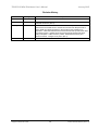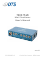
1
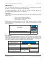
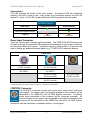
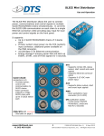
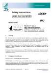
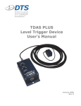
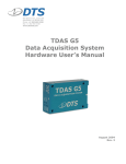
TDAS PLUS Mini Distributor User’s Manual January 2015 10500-00050-MAN (Rev. 2) © Diversified Technical Systems, Inc. - All Rights Reserved TDAS PLUS Mini Distributor User’s Manual January 2015 Table of Contents DTS Support ....................................................................................................................... 3 Introducing the TDAS PLUS Mini Distributor .................................................................. 4 TDAS PLUS Mini Distributor Control Panel ..................................................................... 4 LED Indicators ................................................................................................................. 6 Power Status ............................................................................................................... 6 TDAS Systems ............................................................................................................ 6 System Status ............................................................................................................. 7 Power Input Connector .................................................................................................... 7 CONTROL Connector ...................................................................................................... 7 UMBILICAL Connector .................................................................................................... 8 Locking Toggle Switch ..................................................................................................... 8 TDAS Systems Connectors ............................................................................................. 8 Crashlink-compatible Interface ...................................................................................... 9 Basic Care and Handling ................................................................................................... 9 Shock Rating.................................................................................................................... 9 Mounting Considerations ............................................................................................. 9 Thermal Considerations ................................................................................................. 10 Power Management.......................................................................................................... 10 Input/Output Power Limits .............................................................................................. 10 Critical Signal Back-up ................................................................................................... 11 Charging/Powering other TDAS Equipment via the TDAS PLUS Mini Distributor .......... 11 Power Requirements of TDAS and SLICE Equipment .............................................. 11 Equipment Interconnections ........................................................................................... 12 Communication Features ................................................................................................ 12 Grounding ......................................................................................................................... 13 Appendix A: Connector Information.............................................................................. 14 Suggested Connector Sources ...................................................................................... 17 Appendix B: Mechanical Specifications........................................................................ 18 Appendix C: Input Power Calculations ......................................................................... 19 support.dtsweb.com ii 10500-00050-MAN (Rev. 2) TDAS PLUS Mini Distributor User’s Manual January 2015 DTS Support TDAS systems are designed to be reliable and simple to operate. Should you need assistance, DTS has support engineers worldwide with extensive product knowledge and crash test experience to help via telephone, e-mail or on-site visits. The best way to contact a DTS support engineer is to submit a request through the DTS Help Center web portal (support.dtsweb.com). You must be registered (support.dtsweb.com/registration) to submit a request (https://support.dtsweb.com/hc/enus/requests/new). Registration also enables access to additional self-help resources and non-public support information. This manual supports the following products: 10500-00050: TDAS PLUS Mini Distributor (Crashlink-compatible input) 10500-00060: TDAS PLUS Mini Distributor (15 V input) (retired) 10500-00061: TDAS PLUS Mini Distributor (15 V, LEMO input) (retired) 10500-00070: TDAS PLUS Mini Distributor (24 V input) 10500-00080: TDAS PLUS Mini Distributor (48 V input) 10500-00130: TDAS PLUS Mini Distributor (10-36 V input) 10500-00131: TDAS PLUS Mini Distributor (10-36 V, LEMO input) support.dtsweb.com 3 10500-00050-MAN (Rev. 2) TDAS PLUS Mini Distributor User’s Manual January 2015 Introducing the TDAS PLUS Mini Distributor TDAS PLUS Mini Distributors function as interface units for TDAS PRO, TDAS G5 and iCrash data acquisition products and serve to simplify hardware integration. Supplying power and integrating communication, control, event, and status signals, they are available in several configurations to meet a variety of user requirements around the world. This manual discusses the features available with the TDAS PLUS Mini Distributor. To identify the specific hardware included with your system, please see your packing list. Built and tested for 100 g dynamic testing environments. DTS standard DC power input connector or Crashlink-compatible interface options available. Provides 15 V output power for up to four TDAS and iCrash devices including iDummy systems. Integrates power, communication, event, and status signals. Over- and undervoltage protection, overcurrent protection and power input polarity protection. Individual system status, all-system status and power status LED indicators. Integral threaded mounting holes. TDAS PLUS Mini Distributor Control Panel All connectors and LED indicators are accessible from the front panel. Power input connector (dedicated or via Crashlink-compatible interface), Communication and control signals, Event input and output signals, System status and start record signals, Locking toggle switch for power control, Power status, individual and all-system status LED indicators. Appendix A contains connector information and pin assignments. Appendix B details the unit’s mechanical specifications. A discussion of the LEDs begins on page 6. Pictures of the different front panels are shown below. (Newer front panels have slightly different markings. This does not affect function.) support.dtsweb.com 4 10500-00050-MAN (Rev. 2) TDAS PLUS Mini Distributor User’s Manual January 2015 Crashlink-compatible (P/N 10500-00050) 15 VDC Input (P/N 10500-00060) (P/N 10500-00061 with LEMO input not shown.) 24 VDC Input (P/N 10500-00070) 48 VDC Input (P/N 10500-00080) 15 VDC input (P/N 10500-00130) (P/N 10500-00131 with LEMO input not shown.) support.dtsweb.com 5 10500-00050-MAN (Rev. 2) TDAS PLUS Mini Distributor User’s Manual January 2015 LED Indicators The TDAS PLUS Mini Distributor has a variety of LEDs to provide power and system information. LED behavior is summarized in the tables below. A thorough understanding of the LED states will facilitate an efficient approach to troubleshooting and a quick resolution to any problems. Power Status If this LED is off and you have power going to the unit but no output voltage, this can mean several things: 1. Input voltage not within specifications, 2. Input current is not within specifications, 3. Input polarity is not correct. Disconnecting any attached equipment from the TDAS Systems connectors can help identify whether input or output power is involved. Additional troubleshooting can further isolate the problem. Power Status Input power OK (voltage, current and polarity OK) Input voltage too high TDAS Systems These LEDs function independently of each other. If the LED remains red, an Ethernet link has not been established and the problem will need to be resolved before continuing. If the LED remains off when the DAS is connected and the toggle switch is in the ON position, check that the attached equipment is powered up and working properly. TDAS Systems (x4) Ethernet link established Communication active Ethernet link not established Circular Buffer Mode Recorder Mode DAS armed and ready DAS collecting data support.dtsweb.com 6 10500-00050-MAN (Rev. 2) TDAS PLUS Mini Distributor User’s Manual January 2015 System Status This LED indicates the health of the entire system. All attached DAS are functioning properly if this LED is green or red. If any system is not functioning properly, the LED will remain off. (Note: An off LED can also indicate the DAS is armed in recorder mode.) DAS Status Circular Buffer Mode Recorder Mode (1 second) (1 second) Armed Start record signal received Triggered Power Input Connector There are 3 power input connector options available. The TDAS PLUS Mini Distributor can be used to charge all connected DAS equipment simultaneously if input power is sufficient and the power status LED is green. (The switch may be in either position.) It should not be used to charge any dedicated external battery (e.g., TDAS PLUS Crashworthy Battery). Power Input 15-36 VDC range* (15 VDC nominal) 15 VDC pass through, 15 A max** (DC INPUT) 10-36 VDC range (15 VDC nominal) 15 VDC pass through, 15 A max** (DC INPUT) 18-36 VDC range (24 VDC nominal) 36-60 VDC range (48 VDC nominal) 18-36 VDC range (24 VDC nominal) * The LEMO input version of this model is not rated for input voltages below 15 VDC. ** This model does not contain a power converter (i.e., VDC input = VDC output). CONTROL Connector The CONTROL connector contains start record input, status output and event input signals. An external start record signal received by this connector will be transmitted to the UMBILICAL and all TDAS System connectors. An internal status signal transmitted to this connector will be forwarded externally. All external contact-closure and/or logic-compatible event signals received by this connector will be transmitted to the UMBILICAL connector, all TDAS System connectors, and the Crashlink-compatible interface, if so equipped. support.dtsweb.com 7 10500-00050-MAN (Rev. 2) TDAS PLUS Mini Distributor User’s Manual January 2015 UMBILICAL Connector The UMBILICAL connector contains Ethernet for transmit and receive, start record, status and event signals. Internal and external communications are supported using the industry-standard Ethernet 10/100BaseT/Tx communication protocol. An external start record signal received by this connector will be transmitted to all TDAS System connectors and the Crashlink-compatible interface, if so equipped. An external status signal received by this connector will be forwarded to all TDAS System connectors and the Crashlink-compatible interface, if so equipped. An internal status signal transmitted to this connector will be forwarded externally. A contact-closure event signal received by this connector will be transmitted to the CONTROL connector, all TDAS System connectors, and the Crashlink-compatible interface, if so equipped. This event (T=0) signal path should be used when the event signal is generated off-board or must be transmitted to other systems. This connector does not support logic-compatible event signals. (Use the CONTROL connector if you require support for logic-compatible event signals.) Note that all start record input and output signals are logic-compatible. Locking Toggle Switch When the toggle switch is in the ON position, all internal control system electronics, including output power, are energized and the unit is fully functional. (This is the normal operating mode.) When the switch is in the iCrash or OFF position, only output power is active. The toggle switch can be in either position to charge attached equipment. Note: You must pull out on the switch before moving--do not force. TDAS Systems Connectors These connectors are identical and contain power, Ethernet, start record output, status input, status output, and event signals. Each connector provides conditioned, nominal 15 VDC, 4.5 A output power for use with TDAS equipment. (Note: The 15 VDC power pass-through model does not provide regulated power.) Internal and external communications are supported using the industry-standard Ethernet 10/100BaseT/Tx communication protocol. A start record signal received by the CONTROL connector, UMBILICAL connector or Crashlink-compatible interface will be transmitted to each TDAS System connector and forwarded externally. A status signal received by any one connector will be transmitted to the other three and forwarded to the CONTROL connector, UMBILICAL connector, and Crashlink-compatible interface, if so equipped. A contact-closure event signal received by one connector will be transmitted to the CONTROL, UMBILICAL, other TDAS System connectors, and Crashlink-compatible interface, if so equipped. support.dtsweb.com 8 10500-00050-MAN (Rev. 2) TDAS PLUS Mini Distributor User’s Manual January 2015 WARNING: RDC cables should not be attached to TDAS Systems connectors. To do so will likely result in damage to your equipment. Crashlink-compatible Interface In addition to input power, the Crashlink-compatible interface also supports opto-isolated bidirectional start record and event (T=0) signals, and external Ethernet 10Base2 communications. Pins 5 and 6 support CAN (status loop) termination with 0 ohm. This connector does not support logic-compatible event signals. Basic Care and Handling The TDAS PLUS Mini Distributor is designed to operate reliably in 100 g dynamic testing environments. Though resistant to many environmental conditions, care should be taken not to subject the unit to harsh chemicals, submerge it in water, or drop it onto any hard surface. WARNING: Electronic equipment dropped from desk height onto a solid floor may experience as much as 10,000 g. Under these conditions, damage to the exterior and/or interior of the unit is likely. TDAS PLUS equipment is not user-serviceable and should be returned to the factory for service or repair. When transporting the unit, treat it as you might a laptop computer and you should have no problems. We suggest that you always place the unit in the padded carrying case originally provided with your unit when it is not in use or if shipping is required. Shock Rating The TDAS PLUS Mini Distributor is rated for and fully tested to 100 g, 12 ms duration, in all axes. Mounting Considerations The unit should be securely bolted to the test article or dynamic testing device to provide the best shock protection. Mounting methods and hardware selection should be carefully calculated to withstand expected shock loading and facilitate proper grounding. Check bolt tightness periodically to ensure that 1) the unit is securely fastened to the baseplate, and 2) support.dtsweb.com 9 10500-00050-MAN (Rev. 2) TDAS PLUS Mini Distributor User’s Manual January 2015 the baseplate is securely fastened to the testing platform. (See Appendix B for the unit’s mechanical specifications.) Thermal Considerations It is unlikely that the unit will overheat if common-sense measures are taken. Under normal conditions, the unit will get warm to the touch when a full load is applied continuously. The unit’s internal fan and the application of a heat sink provided by bolting the unit to a structure of significant thermal mass will keep the temperature well within acceptable limits for any extended period in use at the maximum power output level. If high ambient temperatures, exposure to other heat sources or severely restricted airflow will cause case temperatures in excess of 70°C, the airflow created by a small fan will increase heat transfer by a factor of 3 to 5. Additionally, do not block or restrict air intake or exhaust (fan) to or from the unit and always shield the unit from exposure to direct sunlight. When in doubt, measure the case temperature of the unit and take whatever steps are necessary to improve heat transfer. Power Management A good power source is of paramount importance. The TDAS PLUS Mini Distributor should be powered from a high-quality power source with output voltage and current ratings appropriate for the installation. A green power status LED means voltage and current input levels are within specifications and polarity is correct. (A discussion of the power status LED begins on page 6.) All TDAS Systems connectors are driven by one power converter that provides nominal 15 V, 4.5 A output power per connector. Each connector has a maximum output current protection threshold of 5 A using self-resetting fuses. If one output should shutdown, the other three will not be affected, assuming power and current thresholds are not exceeded. Important note: The 15 VDC power pass-through unit does not contain a power converter. Please pay close attention to the input voltage at the power input connector as this is the voltage that is supplied, or passed through, to the attached equipment (i.e., VDC input = VDC output). Input/Output Power Limits The maximum input and output power limits are dependent on the model. Model Maximum Input Power Maximum Output Power (total) 10-36 VDC range 15 VDC pass through 18-36 VDC range 36-60 VDC range 225 W 225 W (15 V at 15 A)* 360 W 360 W 200 W 225 W 270 W 270 W * This model does not contain a power converter (i.e., VDC input = VDC output). There may be additional restrictions based on the input connector. See page 7 for details. support.dtsweb.com 10 10500-00050-MAN (Rev. 2) TDAS PLUS Mini Distributor User’s Manual January 2015 Critical Signal Back-up The TDAS PLUS Mini Distributor contains a capacitive device to support critical test signals should external power be disconnected during data collection. Status, start record and event signals are enabled for ~1 minute in the event of power loss. (Note: Main output power and Ethernet communications are not supported.) When connected to sufficient external power, the unit will be ready to support these critical signals after a few minutes. Charging/Powering other TDAS Equipment via the TDAS PLUS Mini Distributor With sufficient external power connected, the TDAS PLUS Mini Distributor can be used to charge/power TDAS PRO racks (including any modules), TDAS G5 Docking Stations, and other TDAS equipment containing an internal battery. (Note: The TDAS PLUS Crashworthy Battery is considered an external battery and should not be charged via the TDAS PLUS Mini Distributor.) The length of time required to charge all equipment depends primarily on the discharge state of the batteries. Please see the discussion on “Equipment Interconnections” beginning on page 12 for information on how to connect the equipment together. Attached TDAS equipment will charge with the toggle switch in either position. When the toggle switch is in the iCrash or OFF position, only output power is on. When the toggle switch is in the ON position, all internal control system electronics, including output power, are energized and the unit is fully functional. (This is the normal operating mode.) WARNING: The TDAS PLUS Mini Distributor should NOT be used to charge any external battery, including the TDAS PLUS Crashworthy Battery. The TDAS PLUS Mini Distributor has no power management abilities suitable for this type of charging. Improper charging can result in overheating, possible leakage, or severe battery damage. Power Requirements of TDAS and SLICE Equipment TDAS and SLICE DAS use extensive power management to minimize power consumption. The lowest power demand condition is during charging when power is off. Current demand is at its maximum when the systems are fully armed and powering full sensor loads. Power requirements for TDAS PLUS equipment vary greatly; please review the appropriate user manual for information. TDAS and SLICE User’s Manuals are available from the Help menu within your software. support.dtsweb.com 11 10500-00050-MAN (Rev. 2) TDAS PLUS Mini Distributor User’s Manual January 2015 Power Consumption (per item) Power Off (charging battery) Power On (armed + max load) TDAS PRO - SIM, TOM, DIM - Rack TDAS G5 VDS (incl. DAS) SLICE PRO 25 mA 600 mA 600 mA 500 mA 1A 1A 2A 1A For example, the minimum current required to charge a TDAS PRO rack with 2 modules is 650 mA; the maximum current required for the same system when operational is 3 A. Equipment Interconnections The TDAS PLUS Mini Distributor is typically provided with a bench-top power supply for system check-out. (Please see Appendix A for connector information and pin assignments.) Additionally, cables from the TDAS System connectors to other TDAS equipment are typically provided with your unit. To identify the specific hardware included with your system, please see your packing list. Connections should be made as follows: 1. Connect the TDAS PLUS Mini Distributor’s power supply to the DC power input or INTERFACE connector on the unit using the cable(s) provided. (A green power status LED means voltage and current input levels are within specifications and polarity is correct.) The unit will be immediately ready for use. 2. Connect the TDAS equipment of choice to any TDAS Systems connector using the appropriate cable (typically a DDX or CPY cable). WARNING: RDC cables should not be attached to TDAS Systems connectors. To do so will likely result in damage to your equipment. 3. Continue in this manner until all equipment has been connected. Communication Features The TDAS PLUS Mini Distributor supports the industry-standard Ethernet 10/100BaseT/Tx communication method. The unit itself does not contain an IP-addressable controller but includes an Ethernet switch to support communications. Note: The Crashlink-compatible interface supports external communications via 10Base2 Ethernet. support.dtsweb.com 12 10500-00050-MAN (Rev. 2) TDAS PLUS Mini Distributor User’s Manual January 2015 Grounding In addition to providing reliable power conversion for TDAS systems, the TDAS PLUS Mini Distributor also provides a means for grounding the entire data acquisition system and the test vehicle. The enclosure of the TDAS PLUS Mini Distributor is connected to pin D of the power input connector (Amphenol MS3474L14-4P) and to the power output pins on the TDAS Systems connectors. (Please see Appendix A for connector information and pin assignments.) DTS strongly recommends that the test vehicle or sled be connected to earth ground. One easy way to do this is to attach a trailing ground cable to the TDAS PLUS Mini Distributor’s power input connector or to the enclosure of the unit. Additionally, it is very important that the enclosures of all TDAS equipment be grounded to each other and the test vehicle or sled structure. This will minimize any risk of data noise due to high-current transients from sources such as vehicle battery shorts or air bag squib shorts. Bolting the units to the vehicle or mounting structure will ordinarily provide proper grounding. DTS recommends checking continuity between the enclosures of each unit and the test vehicle or sled to confirm resistance readings of <1 ohm. If the installation does not permit bolting the TDAS PLUS Mini Distributor and connected TDAS systems to a common ground, DTS recommends connecting ground wires between the various enclosures. Please contact DTS if you have any questions regarding proper methods to ground the system. support.dtsweb.com 13 10500-00050-MAN (Rev. 2) TDAS PLUS Mini Distributor User’s Manual January 2015 Appendix A: Connector Information INTERFACE connector (ECG.4B.856.CLL1) 4-pin power input connector (Amphenol MS3474L14-4P) A D B C (panel view) (panel view) Suggested cable connector P/N: FGG.4B.856.CLAM722 Pin 1 2 3 4 5 6 7 8 9 10 11 12 13 14 15 16 Suggested cable connector P/N: MS3476L14-4S/97-3057-1008-1 (621) Function Pin +VDC input (18-36 VDC) +VDC input (18-36 VDC) -VDC input (power return) -VDC input (power return) CH (termination) CL (termination) -VDC input (power return) +VDC input (18-36 VDC) No connection No connection No connection No connection +Event, bidirectional, isolated (TR0+) -Event, bidirectional, isolated (TR0-) +Start record, bidirectional, isolated (TR1+) -Start record, bidirectional, isolated (TR1-) A B C D +VDC input No connection -VDC input (power return) Enclosure (case ground) 4-pin power input connector (ECG.2B.304.CLL) 1 4 2 3 (panel view) Suggested cable connector P/N: FGG.2B.304.CLADxx C1 Ethernet (10Base2) Pin C1S C2 C2S Ethernet (10Base2) No connection No connection 1 2 3, 4 support.dtsweb.com Function 14 Function +VDC input -VDC input (power return) Enclosure (case ground) 10500-00050-MAN (Rev. 2) TDAS PLUS Mini Distributor User’s Manual January 2015 7-pin CONTROL connector (ECG.2B.307.CLV) 1 19-pin UMBILICAL connector (ECB.2B.319.CLV) 6 2 2 7 3 5 14 4 3 4 5 12 1 13 11 19 18 15 16 17 6 10 9 8 7 (panel view) (panel view) Suggested cable connector P/N: FGG.2B.307.CLADxx Suggested cable connector P/N: FGB.2B.319.CLADxx Pin Function Pin Function 1 +Start record, bidirectional, isolated, 0-5 V signal to pin 2 1 2 No connection Power present signal 2 -Start record, bidirectional, isolated, return line for pin 1 3 4 Shield Start record input, +5 V = start 3 +Event, isolated input, 5-12 V applied with respect to pin 7 5 6 Common for status output +Status output (5 V = OK) 4 Ground for status output 7 Reserved (internal use only) 5 Status output, 0 V/+5 V with respect to pin 4 8 9 Ethernet Rx- (10/100BaseT/Tx) Ethernet Rx+ (10/100BaseT/Tx) 6 +Event, bidirectional, isolated, contact closure to pin 7 10 11 No connection No connection 7 -Event, bidirectional, isolated, contact closure to pin 6 12 13 No connection No connection 14 No connection 15 +Event, bidirectional, isolated, contact closure to pin 19 16 Common for start record 17 Ethernet Tx- (10/100BaseT/Tx) 18 Ethernet Tx+ (10/100BaseT/Tx) 19 -Event, bidirectional, isolated, contact closure to pin 15 support.dtsweb.com 15 10500-00050-MAN (Rev. 2) TDAS PLUS Mini Distributor User’s Manual January 2015 19-pin TDAS Systems connectors (ECA.2B.319.CLV) 2 3 4 5 11 19 18 15 16 17 6 10 3 9 4 8 11 19 18 15 16 17 6 10 9 8 7 (panel view) Suggested cable connector P/N: FGA.2B.319.CLADxx Suggested cable connector P/N: FGG.2B.319.CLADxx* * Early units have single, “G”-keyed connectors. Later units have dual, “A”keyed connectors. Pin assignments are the same for both connectors. Function 2 Power control output (iDummy) (short to ground = on) No connection 3 Shield (ground) 4 5 +Start record to DAS (5 V = start) Signal ground 6 +Status to DAS (5 V = OK) 7 +Status from DAS (5 V = OK) 8 Main power output (+15 VDC) 9 Main power output (+15 VDC) 10 System active signal from DAS 11 Ethernet Rx- (10/100BaseT/Tx) 12 Ethernet Rx+ (10/100BaseT/Tx) 13 Ethernet Tx- (10/100BaseT/Tx) 14 Ethernet Tx+ (10/100BaseT/Tx) 15 17 +Event, bidirectional, isolated, contact closure to pin 19 Common for start record and status input (ground) Main power return 18 Main power return 19 -Event, bidirectional, isolated, contact closure to pin 15 16 14 5 7 12 1 13 2 (panel view) Pin 1 12 1 13 14 (ECG.2B.319.CLV*) support.dtsweb.com 16 10500-00050-MAN (Rev. 2) TDAS PLUS Mini Distributor User’s Manual January 2015 Suggested Connector Sources DTS uses LEMO connectors on the TDAS PLUS Mini Distributor. If you need to purchase connectors, we suggest first going to LEMO directly (http://www.lemo.com). Their web site and worldwide sales team are very helpful. Should you have difficulty obtaining a specific part number, they can suggest connector variations or alternates and explain options that may be useful for your particular application. Another U.S. source is Alpine Electronics (www.alpine-electronics.com) in San Jose, California. They are a stocking distributor for LEMO and LEMO-compatible connectors. Amphenol connectors are also used on the 10-36, 15, 18-36 and 36-60 VDC TDAS PLUS Mini Distributors. There are many distributors for Amphenol and Amphenol-compatible connectors (Cannon, Array, etc.) including Allied, Arrow, Newark and TTI. Contact information for these distributors can be found at http://www.amphenol-industrial.com/. support.dtsweb.com 17 10500-00050-MAN (Rev. 2) TDAS PLUS Mini Distributor User’s Manual January 2015 Appendix B: Mechanical Specifications Weight: 1.82 kilograms 9.252 inches/235 mm 2.008 inches/ 51 mm 4.625 inches/117.48 mm 0.4 inches/ 10.16 mm 1.608 inches/ 40.84 mm M8 x 1.25 pitch screws; should penetrate unit 8 mm 0.492 inches/ 12.5 mm 8.76 inches/222.5 mm Accessories/support equipment: 10600-0003x: Cable, SYSTEM port to COM port + POWER port (CPY) 10600-0006x: Cable, power, DC input to pigtails (DPX) 10600-0017x: Cable, power, SYSTEM port to POWER port (SPO) 10700-0005x: Cable, DBX cable to SYSTEM port (DDX) 10700-0006x: Cable, PC comm, Ethernet via UMBILICAL port (DEC) 10700-0008x: Cable, SYSTEM port to COM port (DRC) 10700-0021x: Cable, PC comm, Ethernet via SYSTEM port (SPE) 10700-0022x: Cable, SYSTEM port to UMBILICAL port (SPU) 10700-0053x: Cable, TDAS PLUS Mini Distributor SYSTEM port event (x = multiple lengths available) support.dtsweb.com 18 10500-00050-MAN (Rev. 2) TDAS PLUS Mini Distributor User’s Manual January 2015 Appendix C: Input Power Calculations The TDAS PLUS Mini Distributor contains high-efficiency power conversion circuitry with a wide input range and a well-regulated 15 V output. (Note: The 15 VDC power passthrough unit does not provide regulated power. Please see page 10 for additional information.) With an appropriate external power supply, the system supplies optimal power for TDAS systems without having to worry about variable voltage drops through the input power cable. It is very important that you choose a power supply and cabling carefully to ensure there is sufficient input voltage at the power input connector (or Crashlink-compatible interface) of the TDAS PLUS Mini Distributor under all circumstances. Power cables have resistance that depends upon the conductor diameter and increases with length. For reference, the following table identifies the nominal wire resistance by gage. Gage Resistance (per foot) Resistance (per meter) 12 0.00162 Ω 0.00531 Ω 14 0.00258 Ω 0.00846 Ω 16 0.00408 Ω 0.01338 Ω 18 0.00652 Ω 0.02139 Ω 20 0.01036 Ω 0.03398 Ω The input power required is directly related to the load placed on the outputs and the applied input voltage. DTS recommends the following strategy to ensure success: 1. Determine the worst-case DAS load. For TDAS PRO equipment, assume 1 A per module or rack. For each TDAS G5 DAS/Docking Station system, assume 2 A per system. 2. Calculate the TDAS PLUS Mini Distributor input current. requirement is as follows: The input current Input current = ((total DAS current) * (15/Vin)*1.25) where 1.25 is the compensation for conversion loss, and Vin = voltage at the input connector of the TDAS PLUS Mini Distributor (after cable loss). 3. Calculate the required power supply and wiring to maintain sufficient input voltage at the unit’s power input connector. (For this example, assume 48 V at the input connector.) Example: Four TDAS G5 DAS/TDAS G5 Docking Station systems (128 channels) Worst-case DAS current = 8 A Input current at 48 V = (8) * (15/48)*1.25 = 3.125 A support.dtsweb.com 19 10500-00050-MAN (Rev. 2) TDAS PLUS Mini Distributor User’s Manual January 2015 Assume that a 100 m power cable is required. Sixteen-gage wire has a nominal resistance of ~1.34 ohm per 100 m. Since current flows through two wires (+ and -), the total resistance will be ~2.68 ohms. The worst-case voltage drop will be 3.125 A * 2.68 ohms = 8.375 V. In this example, a reasonable solution would be to use a 56 V power supply rated for at least 5 A with a 100 m, 16-gage power cable. Please contact DTS if you require assistance. support.dtsweb.com 20 10500-00050-MAN (Rev. 2) TDAS PLUS Mini Distributor User’s Manual January 2015 Revision History Date By 6 Jan 2015 EK Added 4-pin LEMO connector specs to Appendix A. Updated DTS Support boilerplate and footer. (Rev 2) 20 May 2014 EK Added 10-36 VDC variant information. Revised Power Input Connector section. Revised and moved LED section. Revised and moved Power Requirements of (other) TDAS (and SLICE) Equipment. Moved Input Power Calculations to Appendix C. Removed External Power Provisions and Power-up and Power-down Procedures sections. Updated document format and DTS Support and Shock Rating boilerplates. Added accessory cables. Added Revision History and document number. Changed cover photo. (Rev 1) 2 Feb 2006 EK Initial release. (Rev 0) support.dtsweb.com Description 21 10500-00050-MAN (Rev. 2)