1
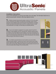
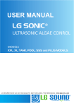
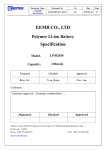
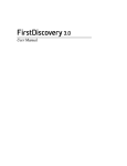
Guidance and manufacturer’s declaration electromagnetic Immunity
5
The EQUIPMENT is intended for use in the electromagnetic environment
specified below. The customer or the user of the EQUIPMENT should assure
that it is used in such an environment
Immunity Test
IEC 60601 Test
Compliance
Electro-magnetic
Level
Level
Guidance Level
IEC 61000-4-3
20V/m
20V/m
Radiated Immunity
80-2500MHz
80-2500MHz
MIL-STD-461E
20V/m
20V/m
Radiated Immunity
100kHz-150kHz
100kHz-150kHz
20V/m
20V/m
13.5MH-13.6MHz
13.5MH-13.6MHz
Portable and mobile RF
communications
equipment should be
used no closer to any
part of the AG Cuffill,
including cables, than
the
recommended
separation
distance
calculated from the
equation applicable to
the frequency of the
transmitter.
Field strengths from
fixed RF transmitters, as
determined by an
electromagnetic site
survey (a) and should
be less than the
compliance level in
each frequency range
(b) Interference may
occur in the vicinity of
equipment
marked
with
the
following
symbol.
NOTE 1 At 80 MHz and 800 MHz, the higher frequency range applies.
NOTE 2 These guidelines may not apply in all situations.
Electromagnetic propagation is affected by absorption and
reflection from structures, objects and people.
a Field strengths from fixed transmitters, such as base stations for radio
(cellular/cordless) telephones and land mobile radios, amateur radio,
AM and FM radio broadcast and TV broadcast cannot be predicted
theoretically with accuracy. To assess the electromagnetic
environment due to fixed RF transmitters, an electromagnetic site
survey should be considered. If the measured field strength in the
location in which the AG Cuffill is used exceeds the applicable RF
compliance level above, the [ME EQUIPMENT or ME SYSTEM] should
be observed to verify normal operation. If abnormal performance is
observed, additional measures may be necessary, such as
re-orienting or relocating the V-touch.
b Over the frequency range 150 kHz to 80 MHz, field strengths should
be less than [V1] V/m.
IEC 61000-4-8
3 A/m
3 A/m
Magnetic Immunity
IEC 61000-4-2
Electronic
Discharge
15 kVAir
15 kVAir
9kV Contact
9kV Contact
Power frequency magnetic
fields should be at levels
characteristic of a typical
location in a typical
commercial or hospital
environment.
Increasing relative humidity
will reduce the potential for
ESD related difficulties.
Guidance and Manufacturer’s Declaration – Electromagnetic emission.
Emission Test
IEC 60601
Level
CISPR11
CLASS B
UMCUFF0021- rev4
Test
15 kVAir
9kV Contact
Eloctro magnetic
Guidance Level
Complies
The AG Cuffill is
suitable for use in all
establishments,
including domestic
establishments and
those directly
connected to the
public low-voltage
power supply
network that
supplies buildings
used for domestic
purposes.
AG Cuffill information regarding Electro-Magnetic Compatibility (EMC)
6
As an electrical device, the AG Cuffill has been tested for electromagnetic
emissions and is susceptible to electromagnetic interferences within the
required criteria of the IEC 60601-1-2 standard.
Warning:
The following warnings and informative tables are provided:
The AG Cuffill has been tested and found to comply with the limits for the medical
devices to the IEC 60601-1-2. These limits are designed to provide reasonable
protection against harmful interference in a typical residential installation. This device
generates, uses and can radiate radio frequency energy and ,if not installed and
used in accordance with the instructions, may cause harmful interference to other
devices in the vicinity.
Recommended separation distance between portable and mobile RF
communications equipment and the AG Cuffill
The AG Cuffill is intended for use in an electromagnetic environment in which
radiated RF disturbances are controlled. The customer or the user of the AG Cuffill
can help prevent electromagnetic interference by maintaining a minimum
distance between portable and mobile RF communications equipment
(transmitters) and the AG Cuffill as recommended below, according to the
maximum output power of the communications equipment.
Separation distance according to frequency of transmitter in meter
Output power of
150 kHz to 80 MHz
80MHz to 800 MHz
800MHz to 2.5GHz
Transmitter in Watts
d=1.2√P
d=1.2√P
d=2.3√P
0.01
0.12
0.12
0.23
0.1
0.37
0.37
0.74
1
1.17
1.17
2.33
10
3.69
3.69
7.38
100
11.67
11.67
23.33
Hospitech Respiration
AG Cuffill
User Manual
Hospitech Respiration
Proprietary Information
For transmitters rated at a maximum output power not listed above, the
recommended separation distance (d) in meters (m) can be estimated using the
equation applicable to the frequency of the transmitter, where P is the maximum
output power rating of the transmitter in watts (W) according to the transmitter
manufacturer. Note1: At 80MHz and 800MHz, the separation distance for the
higher frequency range applies. Note2: These guidelines may not apply in all
situations. Electromagnetic propagation is affected by absorption and reflection
from structures, objects, and people
EC
ONLY
Caution: Federal law restricts
this device to sale by or on the
order of a physician or properly
licensed practitioner (Rx ONLY)
0483
REP
Qsite EU. Gerrit van der Veenstraat 84HS,
1077 EL Amsterdam, The Netherlands
Tel +31(0)(20)811-0550
Fax +31 842-2131-42,
Email: [email protected]
Hospitech Respiration
20, Hamagshimim St P.O.B 7970
Kiryat Matalon Petach-Tikva
4934829, ISRAEL
Tel +972-3-919-1648
Fax +972-3-919-1648
Email:[email protected]
20 ,Hamagshimim St P.O.B 7970
Kiryat Matalon Petach-Tikva
4934829, ISRAEL
Email:[email protected]
0483
AG Cuffill
Description & Identification for Use
1
Instructions for Use
2
Measuring Cuff Pressure: (See the following figure.)
Instructions for Use (cont.)
3
Adjusting Cuff Pressure: (See the following figure.)
Display reads 00:
Normal. Ready For Use.
Display reads UP:
Under Pressure, Vacuum.
The Hospitech AG Cuffill should be used only
under medical supervision in hospitals, pre-hospital
(EMS), extended care facilities and outpatient
clinics, where a patient may be intubated.
The AG Cuffill should not be used for continuous
monitoring. It should be disconnected each time,
after use.
Handling Instructions:
The AG Cuffill is intended for air-filled cuffs and should
not be used with liquids. The AG Cuffill should be kept
in a dry environment during transport and storage.
Cleaning Instructions:
Wipe the surface thoroughly with an alcohol-based
disinfectant. While cleaning, prevent entry of any
fluid into the AG Cuffill luer (inflation line).
Before Use:
Make sure that the luer is clear of any
obstruction and is open to ambient pressure.
4
Display reads1H:
Blinks twice immediately after turn on in case
number of readings left is greater than 99.
The Hospitech AG Cuffill measures and regulates the
cuff pressure of Endotracheal tubes, Tracheostomy
tubes and Laryngeal Masks Airways (supraglottic
airways).
The AG Cuffil is intended for an air-filled
cuff and should not be used with liquids, which
will cause damage.
Display
Display reads OP:
Over Pressure, above 99 mmHg / cmH2O.
1. Turn ON the AG Cuffill by pressing the power
button on the right side of the display.
The display will blink twice showing the
number of readings left and then will
display “00”.(see section 4 - Display)
2. Push the plunger to the distal end of the
syringe (all the way in).
3. Connect the AG Cuffill to the cuff inflation
line and read the pressure value.
4. If required, cuff pressure may be reduced
by pulling back the plunger until required
pressure is achieved.
5. Disconnect the AG Cuffill from the cuff
inflation line.
1. Turn the AG Cuffill ON by pressing the power
button on the right side of the display.
The display will blink twice showing the
number of readings left and then will
display “00”. (see section 4 - Display)
2. Position the plunger about half way out.
3. Connect the AG Cuffill to the cuff inflation
line.
4. Adjust the plunger until the required
pressure is achieved.
If the required pressure is not achieved,
disconnect the AG Cuffill, pull the plunger
1-2 cc backward and repeat this step.
5. Disconnect the AG Cuffill from the cuff
inflation line.
NOTE: The device automatically turns OFF
60 seconds after activation.
NOTE: The device automatically turns OFF
60 seconds after activation.
ATTENTION: When disconnecting, the Cuff
pressure may be reduced by 1-2
mmHg/cmH2O.
ATTENTION: When disconnecting, the Cuff
pressure may be reduced by 1-2
mmHg/cmH2O.
Diagnostics:
Display reads E1 to E4:
System is out of operational range. Device
unusable.
Display reads 01 or above:
Calibration Required. Perform Calibration.
Calibration:
Calibration can only be carried out when the
Cuffill is disconnected from the airway.
• Make sure that the AG Cuffill connector
(Luer) is clear of any obstructions.
• Press and hold the Power Button for more
than 5 seconds.
• ‘- -’ followed by ‘00’ should appear on the
display.
If a value other than ‘00’ appears,the
device is not usable.
Specifications:
Size: Length: 20 cm; Diameter: (ID) 15 mm
Weight: 18 gr
Range of measured cuff pressure:
Model HSCUFF0031: 0-99 mmHg
Model HSCUFF0041: 0-99 cmH20
Recommended temperature operating range:
10ºC - 30ºC (50ºF - 85ºF)
Power: CR1632 3VDC / 130mAh battery
Accuracy of cuff pressure measurement:
Model HSCUFF0031: ±2 mmHg
Model HSCUFF0041: ±2 cmH20
Volume delivered: 0-10 cc in 0.5 cc graduations
Number of operations:
100
EMC Compliance:
IEC 60601-1-2 : RF emissions CISPR 11 Class B
IEC 61000-4-3 , IEC 61000-4-8 ; IEC 61000-4-2
Safety Compliance: IEC 60601-1-1 3rd Edition