1
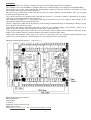
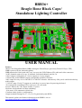
BBB36+
Beagle Bone Black Cape/
Standalone Lighting Controller
USER MANUAL
Features
-Mates with a BeagleBoneBlack (BBB) running the Falcon Player (previously Falcon Pi Player, FPP)
-BBB is powered by the onboard regulator.
-BBB mounts above the board with "easy" access to the USB, Ethernet, SD, audio and video connectors.
-36 DC channels rated at 30A per 18 channels. Individual channels rated at 3A.
-2 Pixel outputs configurable as 2 4 wire outputs or 4 3 wire outputs
-2 Electrically isolated RS485 outputs configurable as DMX or Pixelnet
-2801 output for carry over to 2801DC15 or 2801DC30 boards. Alternatively 2801 pixels could be hooked up
to this output.
-7-36V DC input. If only 5V outputs are used there is a power input for powering the board.
-Test switch with a matching LED to turn on or off a test mode.
-Power LEDs for the 2 DC inputs and the 5V power.
-Real time clock onboard for show scheduling.
-30A (max) ATO (automotive) blade fuse
-Common anode (positive) configuration.
-Output terminals arranged as V+, Ch, Ch, Ch (particularly suits RGB)
This manual, updates and further information on the BBB36+ are on
www.hansonelectronics.com.au/product/BBB36/
Contents
Note: ...................................................................................................................................................................................................... 2
Connections ........................................................................................................................................................................................... 2
CN4-BBB Header.............................................................................................................................................................................. 2
DC Power Input ................................................................................................................................................................................. 2
5V Power ........................................................................................................................................................................................... 2
Dimmer Outputs ................................................................................................................................................................................ 2
LEDS ..................................................................................................................................................................................................... 3
PIXEL OUTPUTS ................................................................................................................................................................................. 3
RS485 OUTPUTS ................................................................................................................................................................................. 3
USING THE BBB36+ ........................................................................................................................................................................... 3
How it works ..................................................................................................................................................................................... 3
Data ................................................................................................................................................................................................... 3
Power ................................................................................................................................................................................................. 3
DC Output configuration within Falcon Player (FPP) ....................................................................................................................... 3
Clock configuration within Falcon Player (FPP) ............................................................................................................................... 3
Test Mode .......................................................................................................................................................................................... 4
Temperature Switch........................................................................................................................................................................... 4
User Headers ..................................................................................................................................................................................... 4
BeagleBoneBlack IO STUFF ................................................................................................................................................................ 4
FAULTFINDING .................................................................................................................................................................................. 5
CONNECTION EXAMPLES ............................................................................................................................................................... 6
WARRANTY ........................................................................................................................................................................................ 8
Note:
Throughout this manual the BeagleBoneBlack is referred to as BBB for the sake of brevity.
Connections
CN4-BBB Header
The connector CN4 on the BBB36+ connects to a BeagleBoneBlack (BBB) via a 46 way ribbon cable. This is the only
connection between the 2 boards. The ribbon cable should be connected to the BBB36+, then the BBB and then the
BBB attached to the 4 standoffs on the BBB36+. See page 4 for location.
DC Power Input
The 2 large 2 way green connectors (CN13, CN14) are the DC inputs from your power supply/s. The +V terminal is
positive and the GND terminal is negative or ground. Any DC voltage in the range of 7V to 36V can be used. There is a
standard ATO (automotive) fuse adjacent to the power terminals. The board comes supplied with 10A fuses fitted.
Fuses up to 30A can be used. It is recommended changing the fuse to the closest size for the total current that the board
is controlling. See page 4 for locations.
5V Power
If both DC dimmer banks are running off 5V then it is necessary to connect a voltage supply of between 7V and 36V
DC to CN26 the PWR connector. If either of the DC dimmer banks has a supply of greater than 7V it isn’t necessary to
connect to CN26. See page 4 for location.
Dimmer Outputs
There are 36 channel outputs. The maximum load per channel is 3 Amps, but the overall limit is 30 Amps per bank of
18. This means that you can't turn on all 18 outputs with the maximum load. In reality, this should not be a problem as
most loads will be less than 2 Amps.
Each group of 3 outputs is grouped into 4 terminals. These are the 3 outputs and a common positive. RGB lights with a
single common anode should have the common wire connected to the terminal +V and the red, green and blue wires to
2
channels 1,2,3 (or 4,5,6 etc). The order and specific channels is actually dependant on what is configured in your
sequencing software. For lights that have single colours (or single channels) per pair of wires then 1 wire gets connected
to the +V and 1 gets connected to the channel output. For led lights which require the polarity to be around the right
way then the anode (positive) gets connected to +V and the cathode (negative) goes to the channel. For lights that do
not have three channels commoned then 3 wires will be joined and fitted to the +V for the 3 channels. See connection
examples later in the manual for examples.
LEDS
There are 4 LEDs on the BBB36+ as well as a number on the BBB. See the falconchristmas website for details on the
LEDs on the BBB. The leds on the BBB36+ are 2 for the power for the 2 banks of DC dimmers. These are labelled
PWR1 and PWR2. There is 1 to indicate that there is a regulated 5V on the board and there is 1 to indicate that test
mode is running.
PIXEL OUTPUTS
There are 2 pixel outputs on the BBB36+. Under control of the Falcon Player these can be configured as a combination
of 2 or 4 wire pixel outputs. The outputs are labelled as A and B rather than Data and Clock as they can both potentially
be configured as Data.
RS485 OUTPUTS
There are 2 electrically isolated RS485 outputs on the BBB36+. Both of these outputs have the optocoupler (6N137)
and RS485 driver chip (MAX1483 or compatible) in IC sockets to allow replacement if they are damaged. The 2
outputs can be configured as DMX or alternatively as Pixelnet from within Falcon Player. The 2 outputs are labelled as
DMX1 and DMX2 and they are wired to an RJ45 socket as per ESTA standard (Data + 1,
Data - 2, Common
7+8). The universe/s for each output are configured within Falcon Player. See page 4 for locations.
USING THE BBB36+
How it works
The smarts of the BBB36+ are actually within the BBB and the Falcon Player software. Sequences are created and
copied to the USB thumbdrive and the BBB either runs by itself as a standalone playback device with the onboard
scheduler in the Falcon Player. Alternately it can be configured as an E1.31 device with the sequence playback
occurring on a computer or another Raspberry Pi, BeagleBoneBlack or similar. This is in bridge mode within the Falcon
Player.
The official home of the Falcon Player software is falconchristmas.com. Information on configuring the Falcon Player,
downloads etc are hosted there.
Data
The pcb has a terminal block (CN5) for getting the data out of the pcb to expansion DC boards. It is a removable screw
terminal and the wire that goes into each position is marked on the pcb. The data into the pcb goes out to other boards or
pixels.
Power
The pcb can be powered by any DC voltage in the range of 7V to 36V from either the DC dimmer bank/s or CN26. If
all the LEDs on the DC dimmer outputs are 5V then the user must connect 7-36V to the terminals on CN26 (PWR). The
BBB is powered via the BBB36+ board via the expansion GPIO header of the BBB and it doesn’t need 5V connected
via the BBB power connector.
DC Output configuration within Falcon Player (FPP)
The 36 outputs of the BBB36+ are connected to the XXXX connection of the BBB. Within the FPP you need to go to the XXXX
tab, go down to XXXX and select XXXX. To enable more than the 36 channels on the BBB36+ if a 2801DC15, 2801DC30, 2801
pixels or a combination of the previous then the required number of channels should be selected.
Clock configuration within Falcon Player (FPP)
The BBB36+ has a battery backed real time clock on it. The 2302 battery used is specified to give about 12 years of battery backup.
If the battery isn’t installed or if the battery is flat/failed the time in the BBB will be lost and schedules will not run on time. The
clock is configured as a DX1307 within Falcon Player and the time is set somewhere.
3
Test Mode
The BBB36+ has an inbuilt test mode and a LED to indicate that it is currently running in test mode. Pushing the test
mode pushbutton on the pcb will enable the test mode, the LED will turn on and something will happen. Pressing it
again will turn off test mode and the LED.
Temperature Switch
The BBB36+ has a temperature “switch” built in. It uses the inbuilt temperature sensing within the BBB to turn on a
Mosfet switch which can be used to drive a relay, fan, heater, alarm or whatever depending on the user. The alarm
temperature and whether it goes off above or below the set temperature is configured within Falcon Player.
User Headers
The BBB36+ has 3 pairs of header pins that allow access to special features. The 3 header pins should only be
connected to via a switch or relay output (voltage free outputs). The first pair of header pins is CN1 (Power SW). This
is a power switch input that allows the BBB to do a soft power off under its own control rather a hard power off.
The second pair of header pins is CN27 (User SW1) and its operation can be configured within Falcon Player.
The third pair of header pins is CN24 (User SW2) and its operation can be configured within Falcon Player.
The user headers may be used to change between sequences for differing brightness levels etc.
BeagleBoneBlack IO STUFF
The BBB is powered via the P9
expansion header of the BBB and
doesn’t need the power to be
applied via BBB power connector.
This information is required for
configuring Falcon Player. The
table below shows the functions,
pins and the BBB GPIO number.
The user switches all switch to gnd
via a 1k resistor and require pullups
enabled within the BBB. The –ve of
the LED is connected to gnd and
the +ve is connected to GPIO1-19.
The 36 DC channels on the
BBB36+ are configured as 2801
pixel channels as are any pixels or
other connected 2801DC channels.
BBB36+ Function
BBB P9 Header Pin No
BBB GPIO Number
CN1 (Power SW)
CN27 (User SW1)
CN24 (User SW2)
DMX1
DMX2
2801DC clock
2801DC data
Pixel 1A
Pixel 1B
Pixel 2A
Pixel 2B
Test switch
Test LED
Real time clock SCL
Real time clock SDA
Temperature Mosfet
Pin 9
Pin 12
Pin 11
Pin 25
Pin 27
Pin 22
Pin 21
Pin 18
Pin 17
Pin 23
Pin15
Pin 14
Pin 16
Pin 19
Pin 20
Pin 24
Power button
GPIO1-28 (1k to gnd)
GPIO0-30 (1k to gnd)
GPIO3-21
GPIO3-19
GPIO0-2
GPIO0-3
GPIO0-4
GPIO0-5
GPIO1-17
GPIO1-16
GPIO1-18 (1k to gnd)
GPIO1-19 (1k to gnd)
I2C2_SCL
I2C2_SDA
GPIO0-15
4
FAULTFINDING
Fault
Magic smoke is released
Solution/solutions
-Go to jail. Do not pass go. Do not collect $200
-Apply for magic smoke restocking. Fee will be charged
5V LED is not lit
-Both fuses are blown
-Power is not connected in the right polarity
-A short is on the 5V terminal
-A short is on the 2801 pixel output or too great a load is connected
Dimmer bank LED is not lit
-Fuse is blown
-Power to the connector is less than approximately 2.7V
-Power is connected in the wrong polarity
BBB Leds not lit
installed
-Cable between BBB GPIO header and BBB36+ CN1 misaligned or not
No output lights working
-Fuse/s is blown
-Data is not being sent out by computer or Falcon Player. Try test mode.
-The schedule within the Falcon Player isn’t active
Channel failing to turn on
-Mosfet transistor has been damaged. The mosfet must be replaced with
the exact same type to ensure correct operation
-PCB track has been fused. Should be evident if bottom of the pcb is
inspected
Channel turned on all the time
-Mosfet transistor has been damaged. The mosfet must be replaced with
the exact same type to get correct operation
Fuse blowing
-Fuse selection too low for lights that are connected
-1 or more lights connected have short circuited wires
No DMX or Pixelnet output
-Configured as the wrong type DMX/Pixelnet
-Universe/s not setup correctly within Falcon Player
-RS485 or optocoupler damaged
No Pixel output
-Configured as the wrong pixel type
-Fuse blown
-Power injection to pixels not wired correctly
-Universe/s not setup correctly within Falcon Player
5
CONNECTION EXAMPLES
Figure 1 shows the typical power
supply connections. 1 of the
power supplies needs to be in the
7-36V range. If the power supply
has sufficient power available
then it can be used to power both
output banks. If 1 power supply
is in the 7-36V range then the
other power supply can be any
voltage in the 0 to 36V range.
Figure 1- Typical power connection
Figure 2 shows how the power is
connected if only 5V lights are
used. In this case the 5V power
connector must be connected to. If
only the PI and the board (but no
DC ouputs) are to be powered then
a 5V power supply connected to
the 5V connector is all that is
required.
Figure 2 - Connection when only
lights below 7V are used
Figure 3 shows the 3 common method of
connecting lights to output channels. Channels
1 to 3 show a RGB 3 channel set of leds
connected with the common positive connected
to the +V terminal. Channels 4 to 6 show 3
single channel lights connected with the 3
positives connected to the 1 +V terminal.
Channels 6 to 12 show 3 pairs of 2 channel
lights connected.
Figure 3 - 3 channel, 1 channel and 2 channel
connections
6
Figure 4 shows how to connect between a BBB36+ and a 2801DC15 to add additional
DC channels. Further 2801DC15 or 2801DC30 boards can be added or alternatively
2801 pixels can be connected. If 2801 pixels are added then the GND connection for
the pixels should be connected to both the pixels and also the BBB36+ GND
connection. The +5 should not be connected to either the pixels or the pixel power
supply.
Figure 4 – BBB36+ to 2801 DC output
Figure 5 shows the BBB mounted in its position on top
of the BBB36+. The BBB is connected via the supplied
IDC cable and connects to the GPIO header of the BBB
and CN1 on the BBB36+. See the BBB documentation
or falconchristmas.com for info on the micro SD
connector, video output, audio output etc.
Figure 5 - BBB36+ with BBB mounted
Figure 6 – BBB Connectors and switches
7
WARRANTY
This light controller is covered by a warranty for a period of 12 months from the time of purchase.
The warranty covers only the BBB36+ controller and not any connected lights, power supplies or BeagleBoneBlack.
The warranty covers only faulty material and workmanship if properly setup and operated in accordance with the
specifications and setup sections of this document.
The repair and or replacement of this controller will only be at the workshop of Alan Hanson. The cost of freight
to/from will be borne by the user.
The warranty does not cover damage to the controller due to misuse i.e.. shorting of outputs, connecting an AC supply,
connecting a supply higher than the rated voltage etc
The controller is supplied as is. Alan Hanson and Hanson Electronics reserves the right to make changes to the
specifications and the design without notification.
Misuse, using this for other than its designed use, water damage, mechanical damage or attempting to modify or repair
your controller will void this warranty.
Alan Hanson and Hanson Electronics shall not be liable for any incidental damage, inconvenience, rental, loss of
profits or any other loss due to the unsuitability, failure or use of this controller.
If the user does not agree to these terms the cost of the product (minus freight) will be refunded on the return of the
product. The controller must be in unused condition and must be returned within 14 days.
Please return this controller with a copy of your invoice if it develops a fault. Any controller returned without a copy
of the invoice will be charged at a standard repair rate. The warranty does not cover freight.
Mounting standoff drilling patterns . (Scaled. Not 1:1)
Enquiries/Repairs/Contact Details :Hanson Electronics
Alan Hanson
16 York St
Eaglehawk Victoria Australia 3556
Mobile 0408 463295
email hanselec @ gmail.com web. www.hansonelectronics.com.au
8