1
ELSR362-00004
RES 3.6 kWh All In One
User Manual
CAUTION
Do not operate with other components not approved by the ESS systems.
(Connecting other products in parallel to Samsung SDI's products may result in
abnormal operation.)
The internet connection is required to use all functions of the ESS system.
If you have a problem, please contact the installer.
The Specifications of the product may be modified without prior notice to improve
product quality.
Australia (Eng.) 05/2015. Rev1.1
Table of Contents
Table of Contents
Table of Contents ......................................................................................................... i
Table of Tables............................................................................................................ iii
Table of Figures .......................................................................................................... iv
1. Information in this Manual .................................................................................... 1
1.1
1.2
1.3
1.4
About this Manual .................................................................................................................................... 1
Target Group .............................................................................................................................................. 1
Additional Information ........................................................................................................................... 1
Symbols Used ............................................................................................................................................ 1
2. Safety ...................................................................................................................... 5
2.1
2.2
2.3
Intended Use.............................................................................................................................................. 5
2.1.1
Installation Application Suitable for Safety ........................................................................ 7
2.1.2
Technical Specifications ............................................................................................................ 9
Safety Guidelines ................................................................................................................................... 13
Symbol Indication ................................................................................................................................. 14
3. Product Overview ................................................................................................ 15
4. Operating Modes ................................................................................................. 16
4.1
4.2
Descriptions of Operation Mode ...................................................................................................... 16
4.1.1
PV-Auto Mode ........................................................................................................................... 16
4.1.2
PV-Only Mode ........................................................................................................................... 17
4.1.3
Battery-Discharge Mode ........................................................................................................ 18
4.1.4
Standby Mode........................................................................................................................... 18
4.1.5
Forced-Charge Mode (Maintenance mode) .................................................................... 19
4.1.6
Stand-Alone Mode .................................................................................................................. 19
4.1.7
Event Check Mode ................................................................................................................... 20
4.1.8
Application Download Mode ............................................................................................... 24
Starting the System............................................................................................................................... 25
4.2.1
Turning off the System ........................................................................................................... 25
5. Communication ................................................................................................... 26
5.1
5.2
5.3
Overview .................................................................................................................................................. 26
Components and LAN Connection .................................................................................................. 26
5.2.1
Essential Components ............................................................................................................ 26
5.2.2
LAN Connection ....................................................................................................................... 26
Homepage ............................................................................................................................................... 27
Australia (Eng.) 05/2015. Rev1.1
i
Table of Contents
5.3.1
Service Terms............................................................................................................................. 27
5.3.2
Membership .............................................................................................................................. 27
5.3.3
Membership Withdrawal ....................................................................................................... 29
5.3.4
Log-In........................................................................................................................................... 29
5.3.5
Password Initialization............................................................................................................ 30
5.3.6
Types of Service Offered ........................................................................................................ 30
5.3.7
Mobile Service .......................................................................................................................... 33
6. Maintenance for Problem Solving ...................................................................... 34
6.1
6.2
Fan Exchange .......................................................................................................................................... 34
Cleaning ................................................................................................................................................... 35
6.2.1
6.3
6.4
Cleaning the Side Cover......................................................................................................... 35
Checking the Event Logs ..................................................................................................................... 36
Checking the Terminals ....................................................................................................................... 36
7. Message Description ........................................................................................... 37
7.1
7.2
7.3
Messages in Normal Operation ......................................................................................................... 37
General Events........................................................................................................................................ 38
7.2.1
INVERTER General Events (Warnings) ................................................................................ 38
7.2.2
INVERTER General Events (Protection) .............................................................................. 39
7.2.3
Battery Discharge General Events ...................................................................................... 41
7.2.4
PV General Events (Protection) ............................................................................................ 43
7.2.5
System General Events (Protection) ................................................................................... 44
7.2.6
BMS General Events ................................................................................................................ 45
7.2.7
EMS/Communication Events ................................................................................................ 47
7.2.8
Single Fault Events................................................................................................................... 47
Significant Events .................................................................................................................................. 48
8. Arrangement of Terms ........................................................................................ 50
9. Contact ................................................................................................................. 51
ii
Australia (Eng.) 05/2015. Rev1.1
Table of Tables
Table of Tables
[Table 1-1: Symbol Description] .................................................................................................................... 4
[Table 2-1: Technical Specifications] ............................................................................................................ 9
[Table 2-2: Inverter symbols] ....................................................................................................................... 14
[Table 3-1: Part Description] ........................................................................................................................ 15
[Table 7-1: Message List]............................................................................................................................... 37
[Table 7-2: Inverter general events warning list]................................................................................... 39
[Table 7-3: Inverter protection list] ............................................................................................................ 41
[Table 7-4: Battery operation general events list .................................................................................. 43
[Table 7-5: PV general events protection list] ........................................................................................ 44
[Table 7-6: System general events protection list] ............................................................................... 45
[Table 7-7: BMS general events list] .......................................................................................................... 47
[Table 7-8: EMS/communication events list] .......................................................................................... 47
[Table 7-9: Single fault events list] ............................................................................................................. 48
[Table 7-10: Significant events list] ............................................................................................................ 49
Australia (Eng.) 05/2015. Rev1.1
iii
Table of Figures
Table of Figures
[Figure 2-1: Electrical connections] .............................................................................................................. 5
[Figure 2-2: Name Plate] .................................................................................................................................. 7
[Figure 2-3: PV connections]........................................................................................................................... 8
[Figure 2-4: Distribution box connection diagram]................................................................................. 8
[Figure 2-5: Derating Curve] ........................................................................................................................ 11
[Figure 2-6: Power efficiency curve of System] ...................................................................................... 11
[Figure 2-7: Power efficiency curve of PV Generation] ........................................................................ 12
[Figure 3-1: Part View of Samsung All in One] ....................................................................................... 15
[Figure 4-1: Front status indication screen] ............................................................................................ 16
[Figure 4-2: PV generation, battery charge, Load use, sell remaining amount] .......................... 17
[Figure 4-3: PV generation, battery discharge, Load use, buy shortage amount] ...................... 17
[Figure 4-4: PV generation, Battery standby, Load use, sell remaining amount] ........................ 17
[Figure 4-5: PV generation, Sell remaining amount]............................................................................ 17
[Figure 4-6: PV generation, Buy shortage amount] .............................................................................. 18
[Figure 4-7: Battery discharge, Load use] ................................................................................................ 18
[Figure 4-8: Battery discharge, Load use, Buy shortage amount] .................................................... 18
[Figure 4-9: Indication screen on Standby Mode]................................................................................. 19
[Figure 4-10: Indication screen on Forced charged Mode] ................................................................ 19
[Figure 4-11: Indication screen on stand-alone mode] ....................................................................... 19
[Figure 4-12: Event occurrence, Grid RMS over current protection] ............................................... 20
[Figure 4-13: Event occurrence, DC link over voltage protection]................................................... 20
[Figure 4-14: Event occurrence, PV string1 reverse connection protection] ................................ 20
[Figure 4-15: Event occurrence, PV string2 reverse connection protection] ................................ 20
[Figure 4-16: Event occurrence, PV string1 over voltage protection]............................................. 21
[Figure 4-17: Event occurrence, PV string1 over current protection] ............................................. 21
[Figure 4-18: Event occurrence, PV string2 over voltage protection]............................................. 21
[Figure 4-19: Event occurrence, PV string2 over current protection] ............................................. 21
[Figure 4-20: Event occurrence, Battery over voltage protection] .................................................. 21
[Figure 4-21: Event occurrence, Battery over current protection] ................................................... 22
[Figure 4-22: Event occurrence, On sequence Inverter DC link event]........................................... 22
[Figure 4-23: Event occurrence, On sequence Battery V/I event] .................................................... 22
[Figure 4-24: Event occurrence, Normal Inverter DC link event] ...................................................... 22
[Figure 4-25: Event occurrence, Normal Battery V/I & BDC DC link event].................................... 22
[Figure 4-26: Event occurrence, On sequence Inverter DC link event]........................................... 23
[Figure 4-27: Event occurrence, Normal Inverter DC link & PV I event].......................................... 23
[Figure 4-28: Event occurrence, Temperature protection] ................................................................ 23
[Figure 4-29: Event occurrence, Over Current TZ Fault]...................................................................... 23
[Figure 4-30: Events occurrence, temperature sensor connection error] ..................................... 23
[Figure 4-31: Event occurrence, PV mis-wiring]..................................................................................... 24
[Figure 4-32: Event occurrence, SPI communication event] ............................................................. 24
[Figure 4-33: Event occurrence, Single fault event] ............................................................................. 24
[Figure 4-34: Event occurrence, Continuously 3 times Inverter fault] ............................................ 24
[Figure 4-35: Indication screen on Application Download Mode] .................................................. 24
[Figure 4-36: Initial indication screen on power on] ............................................................................ 25
[Figure 4-37: Standby state indication screen before the EMS command] .................................. 25
[Figure 5-1: Communication terminal]..................................................................................................... 26
[Figure 5-2: Connecting to the website] .................................................................................................. 28
iv
Australia (Eng.) 05/2015. Rev1.1
Table of Figures
[Figure 5-3: Entering the information to sign up for a membership] ............................................. 28
[Figure 5-4: Log-in page] .............................................................................................................................. 29
[Figure 5-5: Password initialization page] ............................................................................................... 30
[Figure 5-6: Monitoring page] ..................................................................................................................... 31
[Figure 5-7: Consumption report page] ................................................................................................... 31
[Figure 5-8: Forecast page] .......................................................................................................................... 32
[Figure 5-9: Mobile service page]............................................................................................................... 33
[Figure 6-1: Side cover removal]................................................................................................................. 34
[Figure 6-2: Fan removal].............................................................................................................................. 34
[Figure 6-3: Side cover removal]................................................................................................................. 35
Australia (Eng.) 05/2015. Rev1.1
v
Information in this Manual
1. Information in this Manual
1.1 About this Manual
This is the user’s manual for the Samsung 3.6 kWh All in One. This user manual is specially
designed to detail the device’s functions and features. Please read this manual before using
the device to ensure safe and proper use.
1.2 Target Group
This user manual applies only to the Samsung 3.6 kWh All in One.
1.3 Additional Information
The user manual and installation manual can be downloaded from the product download
section at “https://myess.samsungsdi.com”. The specifications of the product can be
changed for improvement without notice.
Also, the software can be updated automatically without notice over the Internet.
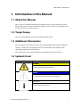
1.4 Symbols Used
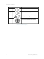
Symbols
Meaning
CAUTION
This symbol indicates a hazardous situation which could
result in a light injury, if not avoided.
NOTICE
This symbol indicates a hazardous situation which could
result in damage to the property, if not avoided.
Information
This symbol indicates valuable tips for optimum installation
and operation of the product.
Australia (Eng.) 05/2015. Rev1.1
1
Information in this Manual
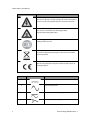
Symbols
Meaning
Beware dangerous voltage.
The inverter operates at high voltage. All works related to the
inverter can only be performed by an electrical technician.
Beware of hot surface.
The inverter can become hot during operation.
Avoid contact during operation.
Follow the guidelines in all relevant documents enclosed
along with the inverter.
Do not dispose of the inverter with household wastes.
For further information on disposal, refer to the installation
manual provided.
The CE Indication:
The relevant equipment complies with the requirements in
the EC guidelines.
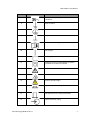
Number
2
Symbol
Description
1
Direct current
2
Alternating current
3
Both direct and alternating current
4
Three-phase alternating current
Australia (Eng.) 05/2015. Rev1.1
Information in this Manual
Number
Symbol
Description
5
Three-phase alternating current with neutral
conductor
6
Earth terminal
7
Protective conductor terminal
8
Frame or chassis terminal
9
Refer to the operating instructions
10
On (supply)
11
Off (supply)
12
Equipment protected throughout by double
insulation or reinforced insulation
13
Caution: Risk of Electric Shock
14
Caution: Hot Surface
15
Caution: Risk of Danger
16
In position of a bi-stable push control
17
Out position of a bi-stable push control
18
Input terminal or rating
Australia (Eng.) 05/2015. Rev1.1
3
Information in this Manual
Number
Symbol
Description
19
Output terminal or rating
20
Bidirectional terminal rating
21
Caution: Risk of Electric Shock and Energy
Storage Timed Discharge
22
Caution: Risk of Hearing Damage and Wear
Hearing Protection Wear hearing protection
[Table 1-1: Symbol Description]
4
Australia (Eng.) 05/2015. Rev1.1
Safety
2. Safety
2.1 Intended Use
NOTICE
The 3.6 kWh All in One system is intended for residential use only.
The 3.6 kWh All in One system should not be used for commercial or
building.
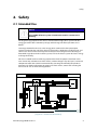
The original usage purpose of this device is for household single-phase system link solar
energy generation and Li-Ion Battery charge and discharge. The basic operations are as
follows.
Samsung 3.6 kWh All In One uses solar energy power connected to the input/output
terminal installed on the side of the device to charge the Li-Ion Battery installed inside, and
converts the direct current electricity of the battery to alternating current to discharge as
household single-phase load or electric system, or uses the electric system of electric energy
to charge the battery.
This device should not be used for any purpose other than the purpose described in this
User manual. Any substitute use of this device, random change in any of its parts, and use of
components other than sold or recommended by Samsung SDI will nullify the product's
guarantee. For further information on proper use of this device, contact the Samsung SDI
Service line or visit at “www.samsungsdi.com”.
[Figure 2-1: Electrical connections]
Australia (Eng.) 05/2015. Rev1.1
5
Safety
Identifying the Product
Attached on the enclosure of this product is the Type Label where the identity of this
product is described. For safe usage, make sure that the following product information is
indicated on the Type Label.
■ Product Name
■ Device Type (Model)
■ Serial Number (Serial No.)
■ Device-specific characteristics
■ Certification Lists
■ Warnings and Notification
The model No. of 3.6 kWh All In One system is defined as below.
■ ELSR362-00004
• ELSR: Residential application
• 36: Battery capacity (x0.1kWh)
• 2: Battery capacity group (Less than 10kW)
• 00004: product line number
The model No. of INVERTER (power conditioning system) is defined as below.
■ SJ94-00108D
• SJ: battery for ESS
• 94: Ass’y
• 00108: product number
• D: National Code (Australia)
The Type Label is shown in the [Figure 2-2].
6
Australia (Eng.) 05/2015. Rev1.1
Safety
[Figure 2-2: Name Plate]
2.1.1 Installation Application Suitable for Safety
This device, Samsung RES 3.6 kWh All in One, is designed to be suitable for household
purposes. The PV Input terminal is composed of two Strings. One PV String input must install
3.3 kW or less PV panel capacity, and the maximum input voltage of the PV String must be
limited to 550V or less.
As shown in the [Figure 2-3], the 3.6 kWh All In One uses the two independent channels of
the PV Input ({PV1+, PV1-}, {PV2+, PV2-}). They are used independently for running the
maximum power from the sources of PV1 and PV2. Two channels are recommended for
independent use for the two PV Inputs. Make sure not to connect one PV string in parallel
with the two independent PV inputs (PV1, PV2). (Refer to 3.6 kWh All In One Solar energy
input connection in the [Figure 2-3]). PV common mode is not allowed.
※PV modules shall have an IEC61730 Application Class A rating or equivalent.
Australia (Eng.) 05/2015. Rev1.1
7
Safety
[Figure 2-3: PV connections]
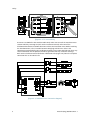
To connect 3.6 kWh All In One with the Public Grid, make sure to install the watt-hour meter
recommended by Samsung SDI (refer to the installation manual) and to install the
distribution box between 3.6 kWh All In One and the Grid watt-hour meter. Before installing
the distribution box, select a suitable location complying with the IP21 and use the
equipment recommended by the installation company. Please note that failure to do so may
cause malfunction and the product will not be guaranteed for any accident or damage.
Refer to the installation manual for further information. The [Figure 2-4] shows the complete
connection line as described so far.
[Figure 2-4: Distribution box connection diagram]
8
Australia (Eng.) 05/2015. Rev1.1
Safety
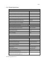
2.1.2 Technical Specifications
PV Data (DC)
Max. input total power
6.6 kWp
Max. input power per string
3.3 kWp
Max. input voltage
550 V
Min. input voltage/Initial input voltage
125 V/150 V
MPPT voltage range
125 V~500 V
Max. input current per string
15 A
Max. input short circuit current for each MPPT
20 A
Max. inverter backfeed current to the array
Negligible
Number of independent MPPT trackers
2
Number of DC inputs pairs for each MPPT
2
Connection type
MC4
Battery Data (DC)
Battery capacity
3.6 kWh
Battery voltage range/nominal voltage
48.0 V~65.9 V/60 V
Battery Max. current
46.3 A
Battery nominal current
33.3 A
Discharge of depth
90% (6000 cycles)
Battery technology
Li-Ion
Nominal DC/DC power
2.0 kW
DC/DC converter technology
Isolated
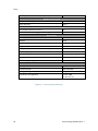
Grid Data (AC)
Rated power (at 230V, 50 Hz)
4.6 kW
Max. apparent power
5 kVA
Nominal voltage/range
230 V/184 V~264 V
Rated power frequency/range
50 Hz/47.5 Hz~51.5 Hz
Max. current
20 A
Max. over-current protection
30 A
Max. allowed current for fuse protection
32 A
Inrush current
68.6 A (peak), 100 μs
Max. output fault current
420 A (peak), 4 ms
Adjustable power factor range
0.95~1~0.95
Feed-in phases/connection phases
1/1
Total Harmonic Distortion.
(Total harmonic factor of the output current with total
harmonic factor of the AC voltage < 2%,
5%
Australia (Eng.) 05/2015. Rev1.1
9
Safety
and AC power > 50% of the rated power)
Efficiency (PV to Grid)
European efficiency
95 %
Max. efficiency
95.5 %
Protective Device
DC disconnection device for PV
No
Ground-fault monitoring/grid monitoring
Yes/Yes
General Data
Dimensions (W/H/D)
1000/680/267 mm
Weight
95 kg
Protective class (I, II, III)
Class I
Degree of protection
IP21
Max. permissible value for relative humidity
95 % (non-condensing)
Operating temperature
-10~40°C
Storage temperature
-20~60°C
Noise emission
≤ 50dB(A) @ 1m
Over voltage category
III
Features
Display
Custom LCD
Communication
LAN, D0, RS485
Energy management system
Integrated
Certificates and approvals
AS/NZS 3100
AS 4777.2/3, CE
[Table 2-1: Technical Specifications]
10
Australia (Eng.) 05/2015. Rev1.1
Safety
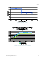
[Figure 2-5: Derating Curve]
[Figure 2-6: Power efficiency curve of System]
Australia (Eng.) 05/2015. Rev1.1
11
Safety
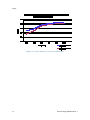
[Figure 2-7: Power efficiency curve of PV Generation]
12
Australia (Eng.) 05/2015. Rev1.1
Safety
2.2 Safety Guidelines
DANGER
High voltages in power conditioning circuits. Lethal hazard of electric shock
or serious burns.
The following work on the inverter must be carried out by qualified
personnel only.
Electrical insulation
Repairs
Modification
Except when under supervision by qualified personnel, children or people
lacking physical, mental, or intellectual capabilities should not work on this
system.
The system should be installed out of the reach of children.
Even when no external voltage is applied to the system, it may have internal
high voltage in the device, which can cause lethal damage to the human
body. High voltage can cause lethal damage to the human body.
CAUTION
Photovoltaic array supplies DC voltage to the 3.6 kWh All In One system. Do
not touch the PV cable when it PV cable is connected to the PV arrays.
CAUTION
Li-Ion battery energy storage system (ESS) inside. When assembling the
system, do not intentionally short the positive (+) and negative (-) terminals
with metallic object.
All work on the ESS and electrical connections must be carried out by
qualified personnel only. The ESS within 3.6 kWh All In One provides a safe
source of electrical energy when operated as intended and as designed.
A potentially hazardous circumstance such as excessive heat or electrolyte
mist may occur due to improper operating conditions, damage, misuse
and/or abuse. The following safety precautions and the warning messages
described in this section must be observed. If any of the following
precautions are not fully understood, or if you have any questions, contact
Customer Support for guidance. The safety section may not include all
regulations for your locale; personnel working with 3.6 kWh All In One must
review applicable federal, state and local regulations as well as the industry
standards regarding this product.
CAUTION
When transporting the All In One system with packaged type units, remove
the battery tray from the All In One system and transport them separately.
Australia (Eng.) 05/2015. Rev1.1
13
Safety
NOTICE
1. Over voltages in the power conditioning circuits.
Any damage to the All In One system will result in voiding of warranty
claims.
Danger to life from electric shock due to damaged 3.6 kWh All in One.
Inadvertent operation of damaged 3.6 kWh All In One can lead to a
hazardous situation that may result in death or serious injury due to
electrical shock. Only operate 3.6 kWh All In One when it is technically
faultless and in an operationally safe stat.
Regularly check the All In One system for visible damage. Make sure that
all safety equipment is freely accessible at all times. If the 3.6 kWh All In
One is damaged, do not touch it. Please immediately contact your
installer or Samsung SDI for arrange for a repair.
2. Please contact your installer or Samsung SDI if a significant event
message is shown on the LCD screen or if the All In One system reports
an event. Refer to the table of event messages for different
significant/general events.
2.3 Symbol Indication
INVERTER Symbols
Symbol
Description
Inverter
dc/dc converter
[Table 2-2: Inverter symbols]
14
Australia (Eng.) 05/2015. Rev1.1
Product Overview
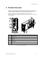
3. Product Overview
The All In One system includes the PV inverter, battery charger/discharger, Li-Ion battery,
and EMS. When compared to previously released products, it is much simpler to install, thus
making it an optimized solution for increasing self-consumption rate at a low cost.
The basic operating modes consist of PV generation mode, PV generation +
charge/discharge mode. The operation mode of this product is automatically determined by
the EMS algorithm.
[Figure 3-1: Part View of Samsung All in One]
-
Description
1
Li-Ion battery
2
INVERTER (PV inverter and battery charger / discharger)
3
Tray BMS
4
Input / Output terminal (MC4-2set and Grid connection terminal -L/N/PE)
5
Cooling Fan
6
Communication terminal block
7
Carrying handle
[Table 3-1: Part Description]
Australia (Eng.) 05/2015. Rev1.1
15
Operating Modes
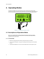
4. Operating Modes
As shown in the [Figure 4-1], the status of this system is displayed in real-time on the
indication screen (LCD screen). This status indication screen extends to 4-digit numbers. The
icons are defined for each state and the details are described in the ensuing subsections.
[Figure 4-1: Front status indication screen]
4.1 Descriptions of Operation Mode
This system is composed of six modes: PV Auto, PV Only, Battery discharge, Standby,
Maintenance (forced charge), and Stand-alone. The event check status should not be
considered as any specific mode.
4.1.1 PV-Auto Mode
16
1.
Both solar energy generation and battery charge-discharge are available.
2.
The solar-generated power is charged or discharged to the battery based on the EMS
decision.
3.
A maximum of 4.6kW or less can be sent to the LOAD and the electric power system.
Australia (Eng.) 05/2015. Rev1.1
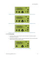
Operating Modes
[Figure 4-2: PV generation, battery charge, Load use, sell remaining amount]
[Figure 4-3: PV generation, battery discharge, Load use, buy shortage amount]
[Figure 4-4: PV generation, Battery standby, Load use, sell remaining amount]
4.1.2 PV-Only Mode
1.
This mode enables the solar energy to be generated. However, the battery chargedischarge does not operate.
2.
A maximum of 4.6 kW or less of solar energy generation power can be sent to the LOAD
and the system based on the EMS decision.
[Figure 4-5: PV generation, Sell remaining amount]
Australia (Eng.) 05/2015. Rev1.1
17
Operating Modes
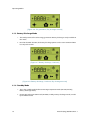
[Figure 4-6: PV generation, Buy shortage amount]
4.1.3 Battery-Discharge Mode
1.
This mode permits of no solar energy generation. Battery discharge is only available on
this mode.
2.
Based on the EMS decision, the battery discharge power can be sent maximum 2kW or
less only to the LOAD.
[Figure 4-7: Battery discharge, Load use]
[Figure 4-8: Battery discharge, Load use, Buy shortage amount]
4.1.4 Standby Mode
18
1.
This is the standby mode before converting to operation mode (PV Auto, PV Only,
Battery discharge mode).
2.
Conversion to the operation mode (PV Auto, PV Only, Battery discharge mode) is made
by the EMS decision.
Australia (Eng.) 05/2015. Rev1.1
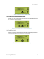
Operating Modes
[Figure 4-9: Indication screen on Standby Mode]
4.1.5 Forced-Charge Mode (Maintenance mode)
(1) In this mode, solar energy generation is not used, but the power continuously flows from
the electric power system to the battery.
[Figure 4-10: Indication screen on Forced charged Mode]
4.1.6 Stand-Alone Mode
When the All In One is disconnected from the energy meter, or the power conversion system
is disconnected from the energy management system (EMS), the All In One system enters
into the Stand-Alone Mode. The system operates in a PV- only mode.
[Figure 4-11: Indication screen on stand-alone mode]
Australia (Eng.) 05/2015. Rev1.1
19
Operating Modes
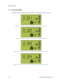
4.1.7 Event Check Mode
This mode stops solar energy generation and put it in standby mode as an event occurs.
[Figure 4-12: Event occurrence, Grid RMS over current protection]
[Figure 4-13: Event occurrence, DC link over voltage protection]
[Figure 4-14: Event occurrence, PV string1 reverse connection protection]
[Figure 4-15: Event occurrence, PV string2 reverse connection protection]
20
Australia (Eng.) 05/2015. Rev1.1
Operating Modes
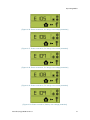
[Figure 4-16: Event occurrence, PV string1 over voltage protection]
[Figure 4-17: Event occurrence, PV string1 over current protection]
[Figure 4-18: Event occurrence, PV string2 over voltage protection]
[Figure 4-19: Event occurrence, PV string2 over current protection]
[Figure 4-20: Event occurrence, Battery over voltage protection]
Australia (Eng.) 05/2015. Rev1.1
21
Operating Modes
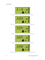
[Figure 4-21: Event occurrence, Battery over current protection]
[Figure 4-22: Event occurrence, On sequence Inverter DC link event]
[Figure 4-23: Event occurrence, On sequence Battery V/I event]
[Figure 4-24: Event occurrence, Normal Inverter DC link event]
[Figure 4-25: Event occurrence, Normal Battery V/I & BDC DC link event]
22
Australia (Eng.) 05/2015. Rev1.1
Operating Modes
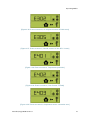
[Figure 4-26: Event occurrence, On sequence Inverter DC link event]
[Figure 4-27: Event occurrence, Normal Inverter DC link & PV I event]
[Figure 4-28: Event occurrence, Temperature protection]
[Figure 4-29: Event occurrence, Over Current TZ Fault]
[Figure 4-30: Events occurrence, temperature sensor connection error]
Australia (Eng.) 05/2015. Rev1.1
23
Operating Modes
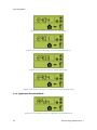
[Figure 4-31: Event occurrence, PV mis-wiring]
[Figure 4-32: Event occurrence, SPI communication event]
[Figure 4-33: Event occurrence, Single fault event]
[Figure 4-34: Event occurrence, Continuously 3 times Inverter fault]
4.1.8 Application Download Mode
[Figure 4-35: Indication screen on Application Download Mode]
24
Australia (Eng.) 05/2015. Rev1.1
Operating Modes
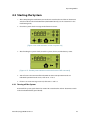
4.2 Starting the System
1.
After completing the installation, turn on the AC circuit breaker and the DC disconnect
switch installed in the distribution box (distribution board). (see the Section 5.7 in the
installation guide)
2.
Check the system check message on the front LCD screen.
[Figure 4-36: Initial indication screen on power on]
3.
After finishing the system check, check the system, the PV, and the battery status.
[Figure 4-37: Standby state indication screen before the EMS command]
4.
You will receive the command from the EMS to convert to operation mode. For
individual operation mode screen, refer to 4.1.1~4.1.6.
5.
If there is an event message received, refer to 4.1.7 and 7.2.
4.2.1 Turning off the System
To turn-off the system, push down the manual AC circuit breaker and DC disconnect switch
in the distribution board (panel board).
Australia (Eng.) 05/2015. Rev1.1
25
Communication
5. Communication
5.1 Overview
When the Internet connection is properly completed, you can monitor the system operation
status on the computer.
5.2 Components and LAN Connection
5.2.1 Essential Components
Internet service line
Wired Router
RJ45 LAN connection cable
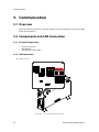
5.2.2 LAN Connection
LAN terminal
[Figure 5-1: Communication terminal]
26
Australia (Eng.) 05/2015. Rev1.1
Communication
Check Internet connection status
You can use the information on the LED lighting status to check the Internet connection
status.
Function per LED
Upper LED: Turns on automatically when connected to the Internet line (Connection).
Lower LED: Blinks when there is data. (Rx, Tx)
LED status on normal connection
The upper LED is On and the lower LED is blinking.
LED status on abnormal connection
Both the upper and lower LEDs are turned Off.
On abnormal connection
Connect the LAN cable again, then check the LED status.
Check whether the Router is Off.
Contact the installation company for repair and maintenance.
5.3 Homepage
Any customer who has purchased this device can use a web browser
(https://myess.samsungsdi.com) or a smart phone to check its current operation status and
receive various statistical information on operation in the house or remotely.
5.3.1 Service Terms
This service is provided only when the device is connected to the Internet, and specific
services may require additional information only after approval from the customer.
5.3.2 Membership
To use this service, you must register for membership through our homepage. During
membership registration, the member’s information such as ID, password, name and the
address are collected, and additional data may also be collected to provide statistical
information upon customer’s approval.
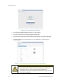
5.3.2.1 Signing up for a membership
1.
2.
3.
Open the browser on an internet-connected device such as PC, notebook or smart
phone
Enter “https://myess.samsungsdi.com ”in the address field of the browser.
When you connect to the website successfully, the screen shown in [Figure 5-2] will
appear.
Australia (Eng.) 05/2015. Rev1.1
27
Communication
[Figure 5-2: Connecting to the website]
4.
Press the "New Account" button to register as a new member.
5.
First time users of the service must sign up for membership.
6.
Enter the required information and additional information to sign up for membership.
7.
Lastly, agree to the service subscription terms and conditions, and then press the
"Submit" button.
[Figure 5-3: Entering the information to sign up for a membership]
CAUTION
28
Items marked with (*) are required.
Family information is optional. If you agree to provide this additional
information, you can receive a variety of analysis information.
If you do not wish to provide additional information later, you can cancel
it from the setting page.
Australia (Eng.) 05/2015. Rev1.1
Communication
5.3.3 Membership Withdrawal
For a customer who does not want to use this service, membership withdrawal is available
through the personal information modification menu on the homepage.
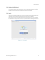
5.3.4 Log-In
Log in to the homepage through the ID and the password generated through membership
registration. You can monitor the product online only when you are logged in.
Also, if a log-in ID error or a password error occurs five consecutive times, access is blocked
for 10 minutes for security reasons, and access is permitted after this waiting period of time.
[Figure 5-4: Log-in page]
Australia (Eng.) 05/2015. Rev1.1
29
Communication
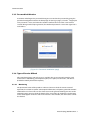
5.3.5 Password Initialization
A customer who forgets the password during use can initialize the password by using the
password initialization menu on the homepage. On the log-in page, select the “Forgot your
id or password? ”menu, and when the customer confirms the ID and the e-mail address
created during membership registration, the initialized password is sent to the registered email address.
[Figure 5-5: Password initialization page]
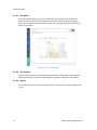
5.3.6 Types of Service Offered
After completing log-in, normal service is available. This service currently provides such
menu items as monitoring, consumption reports, ESS reports, ESS forecasts, and notices.
(Enabled to modify after further update.)
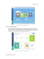
5.3.6.1 Monitoring
The operational status of the product is indicated. You can check the current status of
operation, the customer's power consumption information, and power generation amount
information in real-time. You can also check event codes generated during run time on the
monitoring page. You can check the details of the event codes by clicking the exclamation
marks which appear on the ESS icon. If the Internet is not available, the event codes cannot
be checked.
30
Australia (Eng.) 05/2015. Rev1.1
Communication
[Figure 5-6: Monitoring page]
5.3.6.2 Consumption Report
The household power consumption information collected during energy meter linkage is
provided. In particular, such information on as the household type, the size, and the number
of family residents is collected according to the customer's approval. You can use these data
to identify various types of statistics and comparative analysis data.
[Figure 5-7: Consumption report page]
Australia (Eng.) 05/2015. Rev1.1
31
Communication
5.3.6.3 ESS Report
On the ESS Report page, you can check various types of data generated through ESS
operation. You can also use the ESS Report to check the amount of energy charged or
discharged and other data comparisons with the solar energy production amount or the
power sales amount.
[Figure 5-8: Forecast page]
5.3.6.4 ESS Forecast
In the ESS Forecast menu, the generation amount forecast information and the guide for
optimized operation can be checked through the algorithm mounted on the product.
5.3.6.5 Notices
You can check the notice message whenever there is an update or any other change in the
service.
32
Australia (Eng.) 05/2015. Rev1.1
Communication
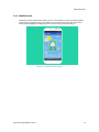
5.3.7 Mobile Service
Customers who use Android or I-Phone can use a smart phone to easily check the product
status anytime, anywhere. To use the mobile service, the customer must first register the
membership through the webpage and use the ID and the password to log-in.
[Figure 5-9: Mobile service page]
Australia (Eng.) 05/2015. Rev1.1
33
Maintenance for Problem Solving
6. Maintenance for Problem Solving
WARNING
Do not disassemble the parts in operation for cleaning purposes. High
voltage can cause lethal damage to the human body.
Please make sure that the AC and DC switch relay in the distribution box is
disconnected before disassembling the system.
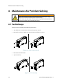
6.1 Fan Exchange
Change the fan according to the following procedures.
1.
Turn off the AC circuit breaker and the DC disconnect switch.
2.
Remove the side cover. Make sure not to remove the front case cover.
[Figure 6-1: Side cover removal]
3.
Remove the fan connector.
4.
Separate the fan.
[Figure 6-2: Fan removal]
34
Australia (Eng.) 05/2015. Rev1.1
Maintenance for Problem Solving
5.
Exchange the fan.
6.
Once the fan has been exchanged, follow the stages from 1 to 4 in reverse order to install
a new fan. Use 1.3~1.6N∙m torque to tighten and fix the screw.
7.
Check the fan state.
8.
Once a new fan has been installed, perform a test operation to check whether there is a
fan event message.
6.2 Cleaning
You should clean the enclosure if it is in a dirty condition, please use a soft brush or a
vacuum to remove the dirt.
Do not use liquids, such as solvents, abrasives, or liquid corrosives in the enclosures.
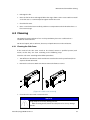
6.2.1 Cleaning the Side Cover
If the inside of the side cover needs to be cleaned, contact a qualified person (tech
nician) so that they can clean according to the following steps:
Clean the side cover according to the follow procedures.
1.
Turn off the DC disconnect switch and the AC circuit breaker on the panel board, then
separate the MC connector.
2.
Remove the side cover. Make sure not to remove the front case cover.
[Figure 6-3: Side cover removal]
3.
Clean the side cover with a vacuum cleaner.
NOTICE
Using compressed air may damage the fan.
When cleaning the fan, do not use compressed air. It may damage
the fan.
Australia (Eng.) 05/2015. Rev1.1
35
Maintenance for Problem Solving
4.
Use a torque screwdriver of 1.3-1.6 Nm and tighten the screws to attach the side cover.
6.3 Checking the Event Logs
You can check the event messages on the website (https://myess.samsungsdi.com) and
identify various causes of the event message described in the following chapter (Chapter 7)
to perform a correct measure. Regarding a significant message, contact the designated
installer or the maintenance company for customer service.
6.4 Checking the Terminals
WARNING
High voltages during operation can cause lethal damage to the human body
if the terminals are touched. Please disconnect the product from the voltage
sources (PV, AC grids).
Ensure that PV connection cables on the PV1+, PV1- and PV2+, PV2- are
fastened.
Check for corrosion on the terminals. If corrosion is seen, please contact the
installer.
Ensure that AC cables in AC1 and AC2 are fastened.
36
Australia (Eng.) 05/2015. Rev1.1
Message Description
7. Message Description
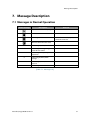
7.1 Messages in Normal Operation
Status message
Description
Remark
Operation mode under progress
NOP State
Warning and fault state
When this icon is displayed,
check the event list.
Normal communication state
kW
Indicating PV, BATT, GRID value
kWh
Indicating the integrating power
value of each mode
Hz
Indicating the frequency under
operation
V
Indicating PV, BATT, GRID
voltage
A
Indicating PV, BATT, GRID
current
%
Indicating BATT SOC
[Table 7-1: Message List]
Australia (Eng.) 05/2015. Rev1.1
37
Message Description
7.2 General Events
The general events contain warnings and protection.
The warning level events does not stop the generating process. A displayed warning
message automatically disappears as soon as the issue is resolved.
When protection level events occur, the product stop the generating process. The process
may automatically resume as long as the issue is resolved.
Checking event codes is available on the website (https://myess.samsungsdi.com).
If the Internet is not available, the event codes cannot be checked.
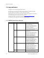
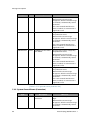
7.2.1 INVERTER General Events (Warnings)
Type
WARNING
38
Code
Description
Measures
E001
GRID UNDER VOLTAGE
When the system voltage drops
below standard level.
This is the overall voltage-current
warning message, with no special
change in the sequence.
The warning message disappears on
reversion to the normal state.
E002
GRID OVER VOLTAGE
When the system voltage rises above
standard level.
This is the overall voltage-current
warning message, with no special
change in the sequence. The
warning message disappears on
reversion to the normal state.
E003
BATT UNDER VOLTAGE
When the battery energy voltage
drops below standard level.
This is the overall voltage-current
warning message, with no special
change in the sequence. The
warning message disappears on
reversion to the normal state.
E004
BATT OVER VOLTAGE
When the battery energy voltage
drops above standard level.
This is the overall voltage-current
warning message, with no special
change in the sequence. The
warning message disappears on
reversion to the normal state.
E005
FAN WARNING
When the Fan operation is abnormal.
This is the overall Fan warning
Australia (Eng.) 05/2015. Rev1.1
Message Description
message, with no special change in
the sequence.
The warning message disappears on
reversion to the normal state.
E006
BATT CONNECTION
WARNING
When the battery connection is
abnormal.
This is the connection warning
message, with no special change in
the sequence.
The warning message disappears on
reversion to the normal state.
[Table 7-2: Inverter general events warning list]
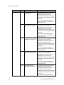
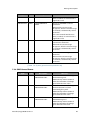
7.2.2 INVERTER General Events (Protection)
Type
Code
PROTECTION
E101
GRID RMS OVER
CURRENT PROTECTION
The product stops the generating
process because a significant
PROTECTION event has occurred.
Wait until the event message
disappears. After the event message
is removed, it automatically returns
to normal.
If it is not removed until the time
limit is reached, it is converted to a
significant event.
E102
DC LINK OVER VOLTAGE
PROTECTION
The product stops the generating
process because a significant
PROTECTION event has occurred.
Wait until the event message
disappears. After the event message
is removed, it automatically returns
to normal.
If it is not removed until the time
limit is reached, it is converted to a
significant event.
E103
PV STRING1 REVERSE
CONNECTION
PROTECTION
The product stops the generating
process because a significant
PROTECTION event has occurred.
Wait until the event message
disappears. After the event message
is removed, it automatically returns
to normal.
If it is not removed until the time
limit is reached, it is converted to a
significant event.
E104
PV STRING2 REVERSE
The product stops the generating
Australia (Eng.) 05/2015. Rev1.1
Description
Measures
39
Message Description
Type
40
Code
Description
CONNECTION
PROTECTION
Measures
process because a significant
PROTECTION event has occurred.
Wait until the event message
disappears. After the event message
is removed, it automatically returns
to normal.
If it is not removed until the time
limit is reached, it is converted to a
significant event.
E105
PV STRING1 OVER
VOLTAGE PROTECTION
The product stops the generating
process because a significant
PROTECTION event has occurred.
Wait until the event message
disappears. After the event message
is removed, it automatically returns
to normal.
If it is not removed until the time
limit is reached, it is converted to a
significant event.
E106
PV STRING1 OVER
CURRENT PROTECTION
The product stops the generating
process because a significant
PROTECTION event has occurred.
Wait until the event message
disappears. After the event message
is removed, it automatically returns
to normal.
If it is not removed until the time
limit is reached, it is converted to a
significant event.
E107
PV STRING2 OVER
VOLTAGE PROTECTION
The product stops the generating
process because a significant
PROTECTION event has occurred.
Wait until the event message
disappears. After the event message
is removed, it automatically returns
to normal.
If it is not removed until the time
limit is reached, it is converted to a
significant event.
E108
PV STRING2 OVER
CURRENT PROTECTION
The product stops the generating
process because a significant
PROTECTION event has occurred.
Wait until the event message
disappears. After the event message
is removed, it automatically returns
to normal.
If it is not removed until the time
Australia (Eng.) 05/2015. Rev1.1
Message Description
Type
Code
Description
Measures
limit is reached, it is converted to a
significant event.
E109
BATT OVER VOLTAGE
PROTECTION
The product stops the generating
process because a significant
PROTECTION event has occurred.
Wait until the event message
disappears. After the event message
is removed, it automatically returns
to normal.
If it is not removed until the time
limit is reached, it is converted to a
significant event.
E110
BATT OVER CURRENT
PROTECTION
The product stops the generating
process because a significant
PROTECTION event has occurred.
Wait until the event message
disappears. After the event message
is removed, it automatically returns
to normal.
If it is not removed until the time
limit is reached, it is converted to a
significant event.
[Table 7-3: Inverter protection list]
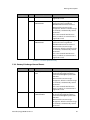
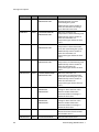
7.2.3 Battery Discharge General Events
Type
Code
PROTECTION
E201
ON SEQUENCE GRID
OFF
While in progress, battery
discharged/charged operation is
terminated through the protection
function.
Wait until the event message
disappears. After the event message
is removed, it automatically returns
to normal.
If it is not removed until the time
limit is reached, it is converted to a
significant event.
PROTECTION
E202
ON SEQUENCE BATT
STATUS EVENT
While in progress, battery
discharged/charged operation is
terminated through the protection
function.
Wait until the event message
disappears. After the event message
is removed, it automatically returns
to normal.
Australia (Eng.) 05/2015. Rev1.1
Description
Measures
41
Message Description
42
Type
Code
Description
Measures
If it is not removed until the time
limit is reached, it is converted to a
significant event.
PROTECTION
E203
ON SEQUENCE INV DC
LINK EVENT
While in progress, battery
discharged/charged operation is
terminated through the protection
function.
Wait until the event message
disappears. After the event message
is removed, it automatically returns
to normal.
If it is not removed until the time
limit is reached, it is converted to a
significant event.
PROTECTION
E204
ON SEQUENCE BATT V &
BATT I EVENT
While in progress, battery
discharged/charged operation is
terminated through the protection
function.
Wait until the event message
disappears. After the event message
is removed, it automatically returns
to normal.
If it is not removed until the time
limit is reached, it is converted to a
significant event.
PROTECTION
E0205
NORMAL GRID OFF
While in progress, battery
discharged/charged operation is
terminated through the protection
function.
Wait until the event message
disappears. After the event message
is removed, it automatically returns
to normal.
If it is not removed until the time
limit is reached, it is converted to a
significant event.
PROTECTION
E206
NORMAL BATT STATUS
EVENT
While in progress, battery
discharged/charged operation is
terminated through the protection
function.
Wait until the event message
disappears. After the event message
is removed, it automatically returns
to normal.
If it is not removed until the time
limit is reached, it is converted to a
significant event.
Australia (Eng.) 05/2015. Rev1.1
Message Description
Type
Code
PROTECTION
E207
NORMAL INV DC LINK
EVENT
Description
While in progress, battery
discharged/charged operation is
terminated through the protection
function.
Wait until the event message
disappears. After the event message
is removed, it automatically returns
to normal.
If it is not removed until the time
limit is reached, it is converted to a
significant event.
Measures
PROTECTION
E208
NORMAL BATT V & BATT
I & BDC DC LINK EVENT
While in progress, battery
discharged/charged operation is
terminated through the protection
function.
Wait until the event message
disappears. After the event message
is removed, it automatically returns
to normal.
If it is not removed until the time
limit is reached, it is converted to a
significant event.
[Table 7-4: Battery operation general events list
7.2.4 PV General Events (Protection)
Type
Code
PROTECTION
E301
ON SEQUENCE GRID
OFF
PV generation mode is stopped by
the protection event.
Wait until the event message
disappears. After the event message
is removed, it automatically returns
to normal.
If it is not removed until the time
limit is reached, it is converted to a
significant event.
PROTECTION
E302
ON SEQUENCE INV DC
LINK EVENT
PV generation mode is stopped by
the protection event.
Wait until the event message
disappears. After the event message
is removed, it automatically returns
to normal.
If it is not removed until the time
limit is reached, it is converted to a
significant event.
PROTECTION
E303
ON SEQUENCE PV V
PV generation mode is stopped by
Australia (Eng.) 05/2015. Rev1.1
Description
Measures
43
Message Description
Type
Code
Description
EVENT
Measures
the protection event.
Wait until the event message
disappears. After the event message
is removed, it automatically returns
to normal.
If it is not removed until the time
limit is reached, it is converted to a
significant event.
PROTECTION
E304
NORMAL GRID OFF
PV generation mode is stopped by
the protection event.
Wait until the event message
disappears. After the event message
is removed, it automatically returns
to normal.
If it is not removed until the time
limit is reached, it is converted to a
significant event.
PROTECTION
E305
NORMAL INV DC LINK &
PV I EVENT
PV generation mode is stopped by
the protection event.
Wait until the event message
disappears. After the event message
is removed, it automatically returns
to normal.
If it is not removed until the time
limit is reached, it is converted to a
significant event.
PROTECTION
E306
NORMAL PV V EVENT
PV generation mode is stopped by
the protection event.
Wait until the event message
disappears. After the event message
is removed, it automatically returns
to normal.
If it is not removed until the time
limit is reached, it is converted to a
significant event.
[Table 7-5: PV general events protection list]
7.2.5 System General Events (Protection)
44
Type
Code
PROTECTION
E401
Description
TEMPERATURE
Protection
Measures
When the switch temperature is
high.
Wait until the event message
disappears. After the event message
is removed, it automatically returns
to normal.
Australia (Eng.) 05/2015. Rev1.1
Message Description
Type
Code
Description
Measures
If it is not removed until the time
limit is reached, it is converted to a
significant event.
PROTECTION
E402
OVER CURRENT TZ
FAULT
Occurs on INVERTER hardware
protection.
Wait until the event message
disappears. After the event message
is removed, it automatically returns
to normal.
If it is not removed until the time
limit is reached, it is converted to a
significant event.
PROTECTION
E403
TEMPERATURE SENSOR
When the temperature sensor
connection is abnormal.
Wait until the event message
disappears. After the event message
is removed, it automatically returns
to normal.
PROTECTION
E404
PV MIS-WIRING
When the PV mis-wiring states is
abnormal.
Wait until the event message
disappears. After the event message
is removed, it automatically returns
to normal.
[Table 7-6: System general events protection list]
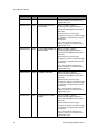
7.2.6 BMS General Events
Type
Code
Description
Measures
WARNING
E501
OVER VOLTAGE
PROTECTION-CELL
When the maximum cell voltage is
above Warning level.
Automatically returns to normal
when the maximum cell voltage
goes below the limit value.
PROTECTION
E502
OVER VOLTAGE
PROTECTION-CELL
When the maximum cell voltage is
above Protection level, thus
terminating the system.
Automatically returns to normal
when the maximum cell voltage
goes below the limit value.
WARNING
E503
UNDER VOLTAGE
PROTECTION-CELL
When the minimum cell voltage is
below Warning level.
Automatically returns to normal
when the minimum cell voltage
goes above the limit value.
Australia (Eng.) 05/2015. Rev1.1
45
Message Description
46
Type
Code
PROTECTION
E504
UNDER VOLTAGE
PROTECTION-CELL
Description
When the minimum cell voltage is
below Protection level, thus
terminating the system.
Automatically returns to normal
when the minimum cell voltage
goes above the limit value.
Measures
WARNING
E505
OVER TEMPERATURE.
PROTECTION-CELL
When the maximum cell
temperature is above Warning level.
Automatically returns to normal
when the maximum cell
temperature goes below the limit
value.
PROTECTION
E506
OVER TEMPERATURE.
PROTECTION-CELL
When the maximum cell
temperature is above Protection
level, thus terminating the system.
Automatically returns to normal
when the maximum cell
temperature goes below the limit
value.
WARNING
E507
UNDER TEMPERATURE.
PROTECTION-CELL
When the minimum cell
temperature is below Warning level.
Automatically returns to normal
when the minimum cell
temperature goes above the limit
value.
PROTECTION
E508
UNDER TEMPERATURE.
PROTECTION-CELL
When the minimum cell
temperature is below Protection
level, thus terminating the system.
Automatically returns to normal
when the minimum cell
temperature goes above the limit
value.
WARNING
E509
CELL VOLTAGE
IMBALANCE
PROTECTION
When the imbalance of the Cell
voltage is above the limit value.
Returns to normal when the
imbalance of the Cell voltage is
below the limit value.
PROTECTION
E510
CELL VOLTAGE
IMBALANCE
PROTECTION
When the imbalance of the Cell
voltage is above the limit value.
Returns to normal when the
imbalance of the Cell voltage is
below the limit value.
WARNING
E511
AFE INITIALIZATION
AFE initialization failure
Restored to normal mode on AFE
initialization success
PROTECTION
E512
AFE INITIALIZATION
AFE communication failure
Australia (Eng.) 05/2015. Rev1.1
Message Description
Type
Code
Description
Measures
WARNING
E513
CELL TEMPERATURE
SENSOR 1EA
Occurs above the standard battery
cell temperature.
PROTECTION
E514
CELL TEMPERATURE
SENSOR 2EA
Occurs above the standard battery
cell temperature.
[Table 7-7: BMS general events list]
7.2.7 EMS/Communication Events
Type
Code
Description
Measures
WARNING
E601
INVERTER
COMMUNICATION
EVENT
Turn off and restart the system.
Reconnect the communication line
between the EMS board and the
DSP board.
WARNING
E602
ETHERNET EVENT
Disconnect and reconnect the LAN.
Turn off and restart the Router.
Make sure that the DHCP server
function of Router is activated.
Turn off and restart the system.
WARNING
E603
ENERGY METER
EVENT
Make sure that the Meter device is
properly selected.
Disconnect and reconnect the D0
cable.
Turn off and restart the system.
[Table 7-8: EMS/communication events list]
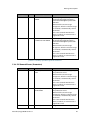
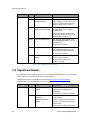
7.2.8 Single Fault Events
Type
WARNING
Code
Description
Measures
E701
GRID UNDER VOLTAGE
FAULT
The operation mode is terminated
when a power system event occurs.
Restart 1 minute after the electric
power system event is settled.
E702
GRID OVER VOLTAGE
FAULT
The operation mode is terminated
when a power system event occurs.
Restart 1 minute after the electric
power system event is settled.
E703
GRID UNDER
FREQUENCY FAULT
The operation mode is terminated
when a power system event occurs.
Restart 1 minute after the electric
power system event is settled.
E704
GRID OVER FREQUENCY
FAULT
The operation mode is terminated
when a power system event occurs.
Restart 1 minute after the electric
Australia (Eng.) 05/2015. Rev1.1
47
Message Description
Type
Code
Description
Measures
power system event is settled.
E705
GRID TEN MINUTE
AVERAGE FAULT
The operation mode is terminated
when a power system event occurs.
Restart 1 minute after the electric
power system event is settled.
E706
RCMU (Residual Current
Monitoring Unit) FAULT
Turn off system power when the
leakage current level is above
standard level.
Check the leakage current level,
then restart or turn off to get back
to the below standard level.
E708
PV INSULATION FAULT
OFF Turn off system power if PV
INSULATION RESISTANCE is at the
standard level.
Restart after 3 minutes.
E709
ANTI ISLANDING FAULT
If the electric power system blacks
out, it automatically detects the
state and turns off the All in One.
Restart after 3 minutes.
E710
FUNCTIONAL SAFETY
FAULT
When the two MCU measuring
values are mismatched.
Restart after 3 minutes if no
problem is found.
[Table 7-9: Single fault events list]
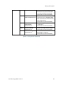
7.3 Significant Events
If a significant event is notified, the system is set to stop operation. If that is the case, contact
your installer to restore the system to normal operation.
Checking event codes is available on the website (https://myess.samsungsdi.com).
If the Internet is not available, the event codes cannot be checked.
Type
Significant
48
Code
Description
Measures
E901
SPI COMMUNICATION
EVENT
Occurs on internal noncommunication between the
INVERTER.
Contact the installer immediately.
E902
CAN (Controller Area
Network)
COMMUNICATION
EVENT
Occurs on non-communication
with the EMS.
When in operation, the All In One
System is converted to the Stand
Alone mode.
Contact the installer immediately.
Australia (Eng.) 05/2015. Rev1.1
Message Description
E903
SINGLE FAULT EVENT
The protection device against
hazards has a defect or a fault that
can cause a hazard has occurred.
Contact the installer immediately.
E904
CONTINUOUSLY 3
TIMES INVERTER FAULT
When INVERTER FAULT occurs three
consecutive times, INVERTER HARD
FAIL is considered to be occurred to
stop the operation.
Contact the installer immediately.
E905
PV CROSS
CONNECTION
Permanent Fail
PV mis-wiring, for example (P1+/P2) or (P2+/P1-).
Contact the installer immediately.
E906
Cell Over Voltage
Permanent Fail
When exceeding Cell Max voltage.
Contact the installer immediately.
E907
Cell Under Voltage
Permanent Fail
When an abnormal decrease in Cell
Min voltage is reported.
Contact the installer immediately.
[Table 7-10: Significant events list]
Australia (Eng.) 05/2015. Rev1.1
49
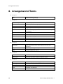
Arrangement of Terms
8. Arrangement of Terms
Chapter 1
RES
Residential Energy Storage
Chapter 2
Li-Ion Battery
Li-Ion Battery
SDI
Abbreviation of Samsung Display and Interface
PV
Photo voltaic
Single phase
A type of phase in electricity
Distribution Box
A box containing AC, DC ON-OFF switches for electricity
distribution
AC
Alternating Current
DC
Direct Current
LCD
Liquid Crystal Display
Inverter
An electric circuit that converts DC to AC and vice versa.
Converter
An electric circuit that converts DC to DC
Chapter 3
INVERTER
Power conversion system which contains inverters and
converters
Tray BMS
Tray battery management system
EMS
Energy management system
Chapter 4
Load
Power load
Power grid
Electricity grid which connects to power system
Chapter 7
50
SOC
State of Charge (battery charging state)
PV String
Describes series connected photovoltaic modules
SPI
Serial port interface
CAN
Controller Area Network
CELL
Battery individual cell
Australia (Eng.) 05/2015. Rev1.1
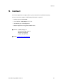
Contact
9. Contact
For technical problems or inquiries for use, please contact the installation company.
To receive customer support, the following information is required.
1. Product type: ELSR362-00004
2. Serial Number: AR00460036Z1********D
3. PV module type and configuration
4. Option equipment: Energy Meter Model Name
■ Address: 150-20, Gongse-ro
Giheung-gueung, Yongin-si
446-557 Gyeonggi-do
KOREA, REPUBBLIC OF
■ E-Mail: [email protected]
Australia (Eng.) 05/2015. Rev1.1
51
Australia (Eng.) 05/2015. Rev1.1


![[ENG-ITA] User's Manual UPS EVO DSP PLUS MM 1.2-2.4](http://vs1.manualzilla.com/store/data/006884869_1-f09fb11d812c485aa10a235685fba597-150x150.png)