1
3.6kWh All In One
SAMSUNG SDI
Installation Manual
1
ENG. Version 140818
Table of Contents
1
2
3
4
5
6
About this Manual .............................................................................................................. 5
1.1
Valid Range........................................................................................................... 5
1.2
Target Group ......................................................................................................... 5
1.3
Manual Storage ..................................................................................................... 5
1.4
Symbol Used ......................................................................................................... 5
Safety .................................................................................................................................. 8
2.1
Intended Usage ..................................................................................................... 8
2.2
Safety Precautions ................................................................................................ 8
2.3
Product Overview ................................................................................................. 9
2.3.1 Battery & PV Inverter Specifications .......................................................... 10
2.3.2 AC specifications ......................................................................................... 10
2.3.3 Grounding the PV Inverter .......................................................................... 11
Package Removal and Inspection ..................................................................................... 12
3.1
Package Removal and Tray Assembly................................................................ 12
3.1.1 Enclosure Package Removal ....................................................................... 12
3.1.2 Battery Tray Package Removal ................................................................... 12
3.1.3 Component check (Packing List) ................................................................ 13
3.1.4 Tray Assembly ............................................................................................. 13
3.2
Checking for Damages in Delivery .................................................................... 14
3.3
Identification of Samsung 3.6kWh All in One ................................................... 14
Installation ........................................................................................................................ 16
4.1
Mounting Location (Installation location) Selection .......................................... 16
4.1.1 Dimensions and Weight ............................................................................... 16
4.1.2 Ambient Conditions..................................................................................... 17
4.1.3 Minimum Clearance .................................................................................... 17
4.1.4 Position (Location Selection) ...................................................................... 17
4.2
Mounting Instructions ......................................................................................... 18
Electrical Connections ...................................................................................................... 20
5.1
Electrical Connection Overview ......................................................................... 20
5.2
Opening the Front Case Cover ........................................................................... 25
5.3
Overview of the Connection Area ...................................................................... 25
5.4
Battery Installation.............................................................................................. 26
5.5
Inner Wiring Connection (Power and Signal Wire Connection for BMS) ......... 27
5.6
Closing the Front Case Cover ............................................................................. 28
5.7
Distribution Box(board) Locking Method .......................................................... 29
5.7.1 AC Circuit Breaker and DC Disconnect Switch ......................................... 29
5.7.2 RCD (residual current device) Leakage Circuit Breaker ............................. 30
5.8
Smart Meter Electrical Connection Installation Method .................................... 31
5.9
Connecting Method of DC line from the PV ...................................................... 31
Communication Connection ............................................................................................. 35
6.1
Internet Connection ............................................................................................ 35
6.1.1 Components ................................................................................................. 35
6.1.2 Connection Block Diagram ......................................................................... 35
6.1.3 Connection Method ..................................................................................... 35
6.2
Smart Meter Connection ..................................................................................... 35
6.2.1 D0 Interface ................................................................................................. 35
6.2.2 S0 Interface .................................................................................................. 36
2
ENG. Version 140818
6.3
6.4
6.5
Recommended Meter List................................................................................... 37
Communication Terminal ................................................................................... 38
Homepage ........................................................................................................... 38
6.5.1 Service Terms .............................................................................................. 38
6.5.2 Membership ................................................................................................. 38
6.5.3 Membership Withdrawal ............................................................................. 38
6.5.4 Log-In .......................................................................................................... 38
6.5.5 Password Initialization ................................................................................ 39
6.5.6 How to Use the Service ............................................................................... 39
6.5.7 Mobile Service ............................................................................................. 42
7 Input of Installation Information....................................................................................... 43
7.1
Information Entering Administrator ................................................................... 43
7.2
System Information Input Flow .......................................................................... 43
7.3
Input PC Direct Connection and Local Setting Value ........................................ 43
7.3.1 PC Direct Connection Flow and Input ........................................................ 43
7.3.2 Insert Jumper Wire....................................................................................... 43
7.3.3 LAN cable connection between PC and System ......................................... 43
7.3.4 Connecting SIM(System Install Manager) .................................................. 43
7.3.5 Input Setting Value ...................................................................................... 44
7.4
Web Page Connection and Input ......................................................................... 45
7.4.1 Web Page Connection .................................................................................. 45
7.4.2 Login & “ESS List” menu ........................................................................... 45
7.4.3 Add new ESS Information ........................................................................... 46
7.4.4 Check current state of ESS .......................................................................... 47
8 Operation Test ................................................................................................................... 48
8.1
Starting the System ............................................................................................. 48
8.2
System Turn-off Method..................................................................................... 48
8.3
Operation Mode Description .............................................................................. 48
8.3.1 PV-Auto Mode ............................................................................................. 49
8.3.2 PV-Only Mode ............................................................................................. 49
8.3.3 Battery-Discharge Mode.............................................................................. 50
8.3.4 Standby Mode .............................................................................................. 51
8.3.5 Forced-Charge Mode (A/S mode) ............................................................... 51
8.3.6 Stand-Alone Mode ....................................................................................... 51
8.3.7 Event Checking Status ................................................................................. 51
8.3.8 APPlication Download Mode ...................................................................... 57
9 Problem confirmation ..................................................................................................... 588
9.1
General Events .................................................................................................. 588
9.1.1 PCS General Events (Warnings) ................................................................ 588
9.1.2 PCS General Events (Protection) .............................................................. 599
9.1.3 Battery Discharge General Events ............................................................... 60
9.1.4 PV General Events (Protection) .................................................................. 62
9.1.5 ETC General Events (Protection) ................................................................ 63
9.1.6 BMS General Events ................................................................................... 63
9.1.7 EMS/Communication Events ...................................................................... 65
9.1.8 Single Fault Events ...................................................................................... 65
9.2
Significant Events ............................................................................................... 66
10
Maintenance ............................................................................................................. 677
10.1
Fan and Cover Cleaning ................................................................................... 677
3
ENG. Version 140818
10.2
11
12
13
14
Various Components Check and Exchange ...................................................... 688
10.2.1 Fuse Check ................................................................................................ 688
10.2.2 Input / Output Terminal Check .................................................................. 688
10.2.3 DC Link Check .......................................................................................... 688
10.2.4 FAN Operation Check ............................................................................... 688
10.3
Battery Maintenance ......................................................................................... 688
10.3.1 Battery Problem Check .............................................................................. 699
10.3.2 Battery Exchange Procedure ..................................................................... 699
10.4
Replaceable Parts Listings .................................................................................. 70
10.4.1 Li-Ion Battery Tray ...................................................................................... 70
10.4.2 PV Connector .............................................................................................. 70
10.4.3 FAN 1 & FAN 2 ........................................................................................... 70
Technical Specifications ............................................................................................ 72
Disassembly ............................................................................................................... 75
12.1
Disassembly ........................................................................................................ 75
12.1.1 Electric Connection Removal ...................................................................... 75
12.1.2 Disassembly of 3.6kWh All in One Main Body .......................................... 75
12.2
Packaging............................................................................................................ 76
12.3
Storage ................................................................................................................ 76
12.4
Disposal .............................................................................................................. 76
Contact ..................................................................................................................... 777
Appendix.................................................................................................................. 788
4
ENG. Version 140818
1 About this Manual
1.1 Valid Range
This is the installation manual for the 3.6 kWh all in one system. Users of this device must
refer to the user’s manual, installation manual.
1.2 Target Group
This installation manual applies only to the Samsung 3.6kWh All in One.
1.3 Manual Storage
The user’s manual and installation manual can be downloaded from the product download
section at “https://myess.samsungsdi.com”. Specification of the product can be change
without any notice to customers for the system improvement.
And software can be update without any notice to customers via internet
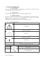
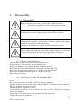
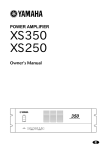
1.4 Symbol Used
Symbols
Meaning
CAUTION!
CAUTION represents hazardous situations which can cause light
injuries if not avoided.
NOTICE!
NOTICE represents the situations which can cause damage to
property if not avoided.
Information
“INFORMATION” provides tips that are valuable for optimum
installation and operation of the product.
Number
Symbol
Description
1
Direct current
2
Alternating current
5
ENG. Version 140818
3
Both direct and alternating current
4
Three-phase alternating current
5
Three-phase alternating current with neutral conductor
6
Earth terminal
7
Protective conductor terminal
Number
Symbol
Description
8
Frame or chassis terminal
9
Refer to the operating instructions
10
On (supply)
11
Off (supply)
12
Equipment protected throughout by double insulation or
reinforced insulation
13
Caution, risk of electrical shock
14
Caution hot surface
Number
Symbol
Description
15
Caution, risk of danger
16
In position of a bi-stable push control
17
Out position of a bi-stable push control
18
Input terminal or rating
19
Output terminal or rating
6
ENG. Version 140818
20
Bidirectional terminal rating
21
Caution, risk of electrical shock,
Energy storage timed discharge
22
Caution risk of hearing damage.
Wear hearing protection
23
24
Do not dispose of the inverter with household wastes.
For detailed disposal information, please refer to the
installation manual provided.
CE indication.
The relevant equipment complies with the requirements
in the EC guidelines.
7
ENG. Version 140818
2 Safety
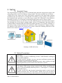
2.1 Intended Usage
The original purpose of this device is for residential grid-connected single-phase system with
solar energy sources and Li-Ion Battery energy storage. The basic operations are as follows.
3.6kWh All in One system uses solar energy power connected to the input/output terminal
installed on the side of the device to charge the Li-Ion battery energy storage or to supply to
the household load, and also to convert the direct current (DC) electricity of the battery to
alternating current (AC) to discharge as household single-phase load or electric system.
It is recommended not to use this device for other than the purpose described in this manual.
The substitute use of this device, random change, and use of components other than sold or
recommended by Samsung SDI will nullify the product guarantee. For example, Samsung LiIon battery energy storage should not be replaced by other manufacturer’s battery storages.
For inquiries on the proper use of this device, please contact the Samsung SDI Service line
(Refer to the contact or www. samsungsdi. com).
Samsung 3.6kWh All in One
2.2 Safety Precautions
CAUTION!
High voltages in power conditioning circuits. Lethal hazards resulting in
electric shock and burns.
All works on the PV modules, inverter, converters and battery systems must
be carried out by qualified personnel only.
Wear rubber gloves, protective glasses and boots when working on high
voltage/high current systems such as PCS and battery systems.
CAUTION!
Li-Ion battery ESS (energy storage system) inside. When assembling the
system, do not intentionally short the positive (+) and negative (-) terminals
with metallic object.
All works on the ESS and electrical connections must be carried out by
qualified personnel only. The ESS inside 3.6kWh All in One provides a
safe source of electrical energy when operated as intended and as designed.
8
ENG. Version 140818
Potentially hazardous circumstances such as excessive heat or electrolyte
mist may occur under improper operating conditions, damage, misuse
and/or abuse. The following safety precautions and warning messages
described in this section must be observed. If any of the following
precautions are not fully understood, or if you have any questions, contact
Customer Support for guidance (see chapter 13).
The safety section may not include all regulations for your locale;
personnel working with 3.6kWh All in One must review applicable federal,
state and local regulations as well as the industry standards regarding this
product.
CAUTION!
This product is intended to be used for PV source inputs and residential
home grids (AC 230V). If not used as intended, the protection provided by
the equipment may be impaired.
CAUTION!
This device is designed appropriate for two-PV string structure. Therefore,
the PV string 1 and PV string 2 must be connected to PV input 1 and PV
input 2, respectively.
Do not split one PV string output for connecting it into the PV input
terminal 1 and input terminal 2.
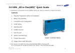
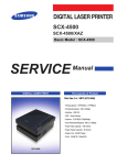
2.3 Product Overview
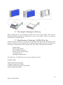
This device is an All in One System including the PV inverter, battery charger / discharger,
Lithium Ion battery, and EMS, and compared to existing products, installation is simple, and
is an optimized solution to increase self-consumption rate at low cost.
The basic operation modes consist of PV generation mode, PV generation + charge/discharge
mode, and battery discharge mode, and the type of operation mode is determined by the EMS
command.
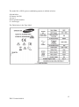
Part Listings
9
ENG. Version 140818
No.
1
2
3
4
5
6
7
Description
Lithium Ion battery
PCS (PV inverter, battery charger / discharger)
Tray BMS
Input / Output terminal (MC4-2set, Grid connection terminal -L/N/PE)
Cooling Fan
Communication
Carrying handle
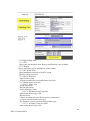
2.3.1 Battery & PV Inverter Specifications
Battery data
Battery Capacity
Battery voltage range/nominal voltage
Battery Max. current
Battery DC/DC data
Nominal Power
Technology
PV inverter connection data
Max. input total power
Max. input power per string
Max. input voltage
Min. input voltage/Initial input voltage
MPPT voltage
Max. input current per string
Number of MPP trackers
Max. number strings
Value
3.6
43.2 ~ 67.2 /60
47
Value
2.0
Isolated
Value
6.6
3.3
550
125/150
125~500
15
2
2
Unit
kWh
Vdc
A
Unit
kW
Unit
kWp
kWp
Vdc
Vdc
Vdc
A
EA
EA
Value
4.6
5
25
32
5
Unit
kW
kVA
A
A
%
230/184~264
50
III
1
V
Hz
phase
Operating temperature
-10~40
°C
Storage temperature
-20~60
°C
2.3.2 AC specifications
Grid connection data
Nominal output power
Max. nominal output power
Max. output current
Max. allowed fuse protection
Harmonic distortion of output current
(at THD<2%, PAC> 0.5 PACnom)
Nominal AC voltage/range
AC grid frequency
Over voltage category
AC connection
10
ENG. Version 140818
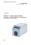
2.3.3 Grounding the PV Inverter
The PV inverter complies with the local requirements for grounding the PV inverter.
Samsung SDI recommends connecting and grounding the PV inverter’s frame and other
electricity conducting surfaces in such a way that there is continuous conduction in order to
achieve maximum protection for systems and persons. And the PV inverter’s DC(+) pole and
DC(-) pole are not permitted to be grounded.
Also, PV module shall be an IEC 61730 Class A rating type.
11
ENG. Version 140818
3 Package Removal and Inspection
CAUTION!
In this box, battery and printed circuit board are included, therefore care
must be taken in handling. Also, the weight is 95kg, therefore more than
two persons must deliver and remove the package.
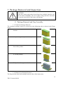
3.1 Package Removal and Tray Assembly
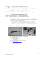
3.1.1 Enclosure Package Removal
The enclosure package removal is carried out in the following order as shown in the Figure
below.
1. Place the system on the installation
location.
2. Open the upper cap of the battery.
3. Remove both sides of the cover in the
front of the product.
4. Lift the package.
5. Open the side support on the bottom.
3.1.2 Battery Tray Package Removal
The Figure below shows the package removal order of the battery tray.
12
ENG. Version 140818
(1) Prepare the product.
(2) Open the box cover
(3) Remove the buffer.
(4) Take out the battery tray. Grab the handle and pull up.
(Please lift with more than two persons. The tray weight is 42.65kg)
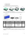
3.1.3 Component check (Packing List)
The Figure and the Table below is an illustration of and a list of components included in the
package on product delivery. Check that the quantity of each component is correct.
-
Object
A
B
C
D
Packing List
Part Name
INVERTER ASSY
TRAY ASSY
1. SCREW(M4xL16)
2. EXTENTION WIRE
3. EXTENTION WIRE
4. EXTENTION WIRE
5. CABLE TIE(A,B)
Quick Guide Manual
Code No.
SJ94-00108A
ELPT362-00031
SJ81-01146
3901-000819
3901-000820
3901-000821
-
Quantity
1
1
10
1
1
1
2
-
1
3.1.4 Tray Assembly
The Figure below is a simple illustration for assembling the battery tray. For the tray
assembly, refer to Clause 5.4 to assemble by referring to the description of electrical
connection.
13
ENG. Version 140818
3.2 Checking for Damages in Delivery
When opening the box with Samsung 3.6kWh All in One system inside, check for any
damage and that the number of components is correct. For example, if there is a scratch on
the enclosure, contact the dealer.
3.3 Identification of Samsung 3.6kWh All in One
On the enclosure of this device, Type Label is attached. In the Type Label, the identity of this
product is described. The contents below are indicated on the Type Label. For safe usage, the
user must be well-informed of the contents in the Type Label. The Type Label includes:
Product Name
Device Type (Model)
Serial Number (Serial No.)
Device-specific characteristics
Certification Lists
Warnings and Notification
The model No. of 3.6kWh All in One system is defined as below.
ESLR362-00001
ESLR: Residential application
36: Battery capacity (x0.1kWh)
2: Battery capacity group (Less than 10kW)
00001: product line number
14
ENG. Version 140818
The model No. of PCS (power conditioning system) is defined as below.
SJ94-00108A
SJ: battery for ESS
94: Ass’y
00108: product number
A: version type
The Table below is the Type Label.
15
ENG. Version 140818
4 Installation
4.1 Mounting Location (Installation location) Selection
Symbols
Meaning
CAUTION!
Danger to life due to fire or explosion!
Danger to life due to high voltages!
Despite careful construction, a fire can occur with electrical devices
Do not install the 3.6kWh All in One:
On flammable construction materials
In areas where highly flammable materials are stored
In potentially explosive areas!
CAUTION!
Li-Ion battery energy storage is inside 3.6kWh All in One.
ESS inside 3.6kWh All in One provides a safe source of electrical energy
when operated as intended and as designed.
Potentially hazardous circumstances such as excessive heat or electrolyte
mist may occur under improper operating conditions, damage, misuse
and/or abuse. The following safety precautions and the warning messages
described in this section must be observed.
If any of the following precautions are not fully understood, or if you have
any questions, contact Customer Support for guidance. The Safety Section
may not include all regulations for your locale; Personnel working with
3.6kWh All in One must review applicable federal, state and local
regulations as well as the industry standards regarding this product.
All works on the ESS and electrical connections must be carried out by
qualified personnel only.
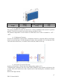
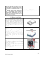
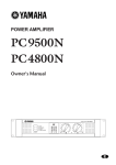
4.1.1 Dimensions and Weight
The dimension of the 3.6kWh All in One after assembly is 1000 x 680 x 267mm. The
weight is 95kg. The Figure below shows the outer dimensions and the weight after assembly.
16
ENG. Version 140818
Weight
Battery
42.8kg
Inverter ( Include case)
52.2kg
Total
95kg
4.1.2 Ambient Conditions
The proper installation location for the device is where installation and removal is possible
anytime. This device must be in a location always possible to reach.
The ambient temperature of the location in which this device will be installed is -10℃ ~
+40℃.
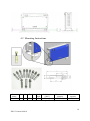
4.1.3 Minimum Clearance
For the safe installation of the product, a minimum clearance is required. Refer to the Figure
below to secure the space. For the minimum clearance, keep a distance of 0.1m from the wall,
1m in the front of the device, 1m and 0.3m on each side, and 0.3m on top.
4.1.4 Position (Location Selection)
Install on a flat surface. (Front, back, left, right gradient within ±0.5°)
Considering the ventilation, the side of the system should be away from the wall about 0.3m
at least. Also, take caution not to have objects stuck in the blowing fan, ventilation entrance
and exit.
Refer to the Figure below.
17
ENG. Version 140818
ㅡ
4.2 Mounting Instructions
Screw
L
name
1/2(M12) 100
S
D
60
17
L1
Drill
Drill depth
Max. tensile
used
(Min.)
capacity
50
17
55(mm)
320(N·m)
[ Anchor bolt specification ]
Max. shear
capacity
340(N·m)
18
ENG. Version 140818
1. Select the drill proper for specifications for drilling.
2. Remove the dust from the hole, and separate the nut and the washer to insert only
the bolt and the cap.
3. Place the product and assemble the washer and the nut to the bolt, and use the
spanner to fasten the nut (7N·m).
※ Required tools for installation
Flat head driver for front cover knob, larger than 10mm
Phillips head driver(No.2) for tray, side cover, grounding
For fastening anchor nuts
Fork lifter with hight: 85-200mm
19
ENG. Version 140818
5 Electrical Connections
Notice!
Static discharge can damage the 3.6kWh All in One!
Before you touch a component inside the 3.6kWh All in One ground yourself by
touching PE or a grounded object
Symbols
Meaning
CAUTION!
When working with the Li-Ion Battery Tray for the 3.6kWh All in One, the
following personal protective equipment must be worn:
High voltage rated rubber gloves
Safety goggles or other eye protection
Standby for 40 minutes for complete discharge within the system before
testing electrical parts inside the system!
Follow the guidelines below when handling the Li-Ion Battery Tray.
Do not intentionally short circuit the positive (+) and negative (-) terminals
with metallic object.
Do not remove insulation cap on the terminals. If insulation cap is
removed, avoid contact between the metals and the battery terminals. Do
not damage the screw thread.
Do not use seriously scarred or deformed battery. Dispose immediately
according to proper regulations.
Do not damage sheath of cable and connectors.
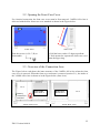
5.1 Electrical Connection Overview
The 3.6kWh All in One has two solar energy inputs (PV1, PV2). For each PV input, 3.3kW
(per string) is the maximum output. The AC output of All in One is connected to the Home
Load and the Grid. Between the Home Load and the Grid, a Digital Energy Meter(Smart
Meter) is placed for power metering. Between the All in One, the AC circuit breaker and DC
Disconnect switch in the distribution box are installed for safety.
Electrical connections
20
ENG. Version 140818
Two independent channels of the PV Input exist in the 3.6kWh All in One as shown in the
figure below, ({PV1+, PV1-}, {PV2+, PV2-}). They are used independently for running the
maximum power from the sources, PV1 and PV2. For the two PV Inputs, independent use of
two channels is recommended. The parallel connection of one PV string into two independent
PV inputs (PV1, PV2) should be avoided (Refer to 3.6kWh All in One Solar energy input
connection in the Figure below). PV common mode is not allowed.
One PV sting should not be commonly connected to the All in One’s two input terminals. In
other words, the split wiring from one PV string output should not connect into two
independent PV inputs (PV1+, PV1- and PV2+, PV2-). (Refer to the PV String connection
method in the Figure below).
The input / output power cable corresponding to the AC, DC input / output specifications in
this system is shown in the Table below.
Recommended cables for 3.6 kWh All in One
Area
Insulation
Color code
Grid (L,N)
6mm
2
600V or more
Black
PE
6mm2
600V or more
Green with Yellow lines
PV (+), (-)
6mm2
700V or more
Black
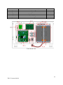
The Figure below is the overall drawing of the system. Please refer to the Figure of the
drawing on installation and maintenance.
Object
A
B
C
D
E
F
G
H
I
BD 1
BD 2
BD 3
BD 4
BD 5
Part List
AC reactor
DC relay
BDC side connector (BATT-A)
Battery side connector (BATT-B)
FAN2
PV1 reactor
PV2 reactor
BDC reactor
FAN1
Board1 (PN. SJ92-01425A)
Board2 (PN. SJ92-01429A)
Board3 (PN. SJ92-01434A)
Board4 (PN. SJ92-01426A)
Board5 (PN. SJ92-01427A)
PCS
PCS
PCS
BATTERY
PCS
PCS
PCS
PCS
PCS
PCS
PCS
PCS
PCS
PCS
21
ENG. Version 140818
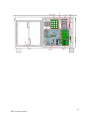
BD 6
BD_BM
BD_CAP
BT_B
BT_T
CP
E_I/O
Board6 (PN. SJ92-01424A)
Board battery management
Board_CAP
Battery Tray bottom view
Battery Tray top view
Communication part
Electrical I/O part
PCS
BATTERY
PCS
BATTERY
BATTERY
PCS
PCS
Front Inside View
22
ENG. Version 140818
Rear Inside View
23
ENG. Version 140818
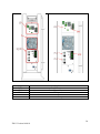
Side View
Object
LCN
SMC
PV 1
PV 2
ACG
Part List
LAN Connector
Smart Meter Connector
PV input 1
PV input 2
AC Grid inputs
24
ENG. Version 140818
5.2 Opening the Front Case Cover
For electrical connection, the front case cover must be first removed. 3.6kWh All in One is
delivered with the blue front case cover attached as shown in the Figure below.
B
A
2
D
C
1
Front View
Side View
Turn the screws (A, B, C, D) to
disassemble.
1. Pull the lower end to 15 degrees gradient.
2. Push upward to separate the front case cover
from the upper ring.
5.3 Overview of the Connection Area
The Figure below each shows the inner structure of the 3.6kWh All in One when the front
case cover is removed. When the front cover enclosure is removed (section 5.1), the inside of
the 3.6kWh All in One is shown as in the Figure below (front view).
PCS
Battery
connection
terminal
BATTERY
REGION A
Inside Front View
BATTERY
REGION A
PCS
Inside Rear View
25
ENG. Version 140818
In the front part of the inside, the PCS circuit
is blocked by the safety shield, only the part
for the battery to be inserted (Region A) is
left.
On the back part, PCS shield is shown, and
On the upper Battery region, BMS circuit
other connection terminals are not shown.
board is seen, and the battery connector
housing must be checked (4EA). Also, there
is battery power connection terminal (red red
circled) in below the device.
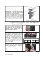
5.4 Battery Installation
1. As shown in subsection 5.2, remove the front
case cover, and lay down the system main body.
The system must be laid for the inside rear view
to face upward. When laying the system, at least
two persons must work together for the worker’s
safety. The Figure on the right is the view when
laid down.
2. To dock the battery on the main body, prepare
the battery tray. Because the battery is heavy, at
least two persons must work together.
In the battery tray, a knob is located on the plate.
The Figure on the right is a view of the battery
tray seen from the enclosure. The battery is
located on the opposite side of the knob
enclosure.
3. The Figure on the right is a view of the battery
tray seen from the battery.
In the battery, the output cable is connected with
the connector.
Also, four BMS and the signal cables come out
from the battery module.
Battery
connector
BMS connector
26
ENG. Version 140818
4. With the main body laid down, hold the tray to
lift up. More than two persons must do this
together. As shown in the Figure on the right, the
battery module must be docked.
Dock battery tray so that ender guide faces the leg
of exterior case of main body (battery terminal
unit needs to face the leg of main body.
On module docking, the battery cable should not
be caught on the Battery frame. After docking,
fasten the screw fixing the tray and the main body.
Use two persons to lift it up. Join by tightening
screw of battery tray with 14~16N∙m of torque
Docking on the laid position
5.5 Inner Wiring Connection (Power and Signal Wire
Connection for BMS)
1. The lead of the battery tray is shown in the
Figure on the right. Two short lines and two
long leads come out from the battery as
shown in the Figure on the right.
2. As described in subsection 5.4, fix the
battery on the 3.6kWh All in One, and check
the signal line of the battery part on the
opposite side. When fixing the battery tray,
take care not to bind the lines or to catch
them on the corner. Plug four cable lines on
the Tray BMS to the upper BMS socket. Plug
in the order of two long lines on the left side
of the BMS, and the short two lines on the
right side of the BMS.
BMS
long
cable
long
cable
short
cable
short
cable
3. Lastly, connect the power cable line
coming out from the battery to the battery
power terminal in the middle.
Connect BATT-A and BATT-B.
BATT-A: Connector on the BDC side,
BATT-B: Connector on the battery side
27
ENG. Version 140818
5.6 Closing the Front Case Cover
1. Hold the front case cover with both hands.
2. Hang the product cover on the upper
surface of the enclosure and push the product
cover forward to close.
3. As shown in the Figure on the right, use a
tool to fix the bolts into the four spots
indicated in red circles.
4. Fix all four sites with the tool (flat driver)
as shown in the Figure.
(Screwing Torque=1.4N∙m)
28
ENG. Version 140818
5.7 Distribution Box(board) Locking Method
The distribution board connected to the PCS, PV and Grid must have the functions mentioned
below.
- AC Grid block function (ex) AC circuit breaker
: 230Vac, 32A, 10kA (short circuit current rating)
- DC block function; DC disconnect switch must be fitted.
PV String1 block function (ex) DC disconnect switch
PV String2 block function (ex) DC disconnect switch
: 650Vdc or more / 15A or more
- RCD(residual current device): Leakage current measure and block
The Figure below shows the connection diagram of the distribution board. The distribution
box receives the DC input (PV string 1, PV string 2) from the solar energy module. Also, the
power grid and the house load are connected to the AC power (L, N).
Distribution box connection diagram
CAUTION
The PV string 1 and the PV string 2 must be each connected to the
distribution box terminal as shown in the distribution board connection
diagram.
Do not change the PV string 1 and PV string 2 to parallel to be connected.
5.7.1 AC Circuit Breaker and DC Disconnect Switch
However, the circuit breaker populated on the distribution board is selected by the installer,
and the installation standard is that a circuit breaker satisfying the voltage and the current
specification of the Grid, PV must be installed. The cables presented in the Table below are
recommended.
29
ENG. Version 140818
Standard
Short circuit current rating
AC circuit breaker
230Vac / 32A
10kA minimum
DC disconnect switch
650Vdc / 15A or more
-
Area
Insulation
Color code
Grid (L,N)
6mm2
600V or more
Black
PE
6mm2
600V or more
Green with Yellow lines
PV (+), (-)
6mm2
700V or more
Black
As illustrated in the Figure, Distribution box connection diagram, the connections from the
All in One system to the distribution box are connected to the terminals of the solar energy
(PVdso1+,PVdso1-,PVdso2+,PVdso2-) of PV1+, PV1-, PV2+, PV2-. Here, the main body
terminals (PV1 +, PV1 -, PV2+, PV2-) and the distribution box terminals are connected in
proper order. Meanwhile for the lines coming from the AC GRID, L, N leads are connected to
the distribution board (LG, NG). The line comes out from the LGO, PGO of the distribution
board to be connected to the L, N terminals of the All in One System.
5.7.2 RCD (residual current device) Leakage Circuit Breaker
This product can cause a DC current in the external protective earthing conductor. Where a
residual current-operated protective (RCD) or monitoring (RCM) device is used for
protection in case of direct or indirect contact, only an RCD or RCM of Type A or Type AC is
allowed on the supply side of this product.
Type AC
AC current sensitive
Type A
AC current sensitive and pulse current sensitive
30
ENG. Version 140818
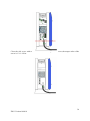
5.8 Smart Meter Electrical Connection Installation Method
The electrical installation method of the digital energy meter(smart meter) must comply with
installation method provided by the digital energy meter(smart meter) manufacturer. However,
selection of the digital energy meter(smart meter) must be done recommended by Samsung
SDI in Chapter 6.3 on the following page.
The Figure below shows the electrical cable connection and the communication lines of the
digital energy meter(smart meter). Depending on the product, there are a one-way meter and
a two-way (bidirectional) meter, and for the one-way meter, two lines must be connected in
series for use. For the two-way meter, one line can be used. Refer to the Figure below and the
communication description in Chapter 6 to install the digital energy meter(smart meter).
House
Load
PV
L
L
Smart
Meter
Distribution
Box
All in One
N
Grid
N
Electric cable connection for Smart meter installation
Depending on the smart meter, the end system of the used lead wiring may be different,
therefore, refer to the smart meter manual.
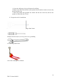
5.9 Connecting Method of DC line from the PV
For the PV module connection, refer to the Figure below. The lead wire coming from the PV
module is connected to the distribution box. For the structure of the distribution box, refer to
subsection 5.7. For the connection to the distribution box, connect each to the terminals of the
solar energy of PV1+, PV1-, PV2+, PV2-. On the other hand, connect the 3.6kWh All in One
main body terminals (PV1 +, PV1 -, PV2+, PV2-) and the distribution box terminals in
proper order. The lead wire thickness is to be as shown in the following Table.
For the connecter (PV1+, PV1-, PV2+, PV2-) connecting from the distribution box to the
3.6kWh All in One input, the type in the Figure below is used (MC4 connector, PV-Stick
Photovoltaic connector “PUSH IN” connection).
31
ENG. Version 140818
PV connector (Left) Male: PV line (Right) Female: All in One system
The Table below shows the lead wire standard of the PV. For the 3.6kWh All in One, 6mm2
thickness of lead wire is recommended.
Area
Insulation
Color code
PE
6mm2
600V or more
Green with Yellow lines
PV (+), (-)
6mm2
700V or more
Black
After opening the side cover, perform the PV, AC connection. (Refer to the contents below).
For the side cover, disassemble the screw to open.
Side cover opening
The Male product is connected to the lead wire coming from the distribution box in the PV
side, and the Female part is attached to the All in One system, and docking is done when
connected together. After opening the side cover, perform the PV, AC connection.
32
ENG. Version 140818
PV connector connection (MC4 connector connection)
In the All in One System, the I/O of the AC power is composed of Terminal socket type.
When connecting the cable to the L and N sockets in the Terminal block, the ring terminal is
attached to the end of the cable to be connected to the main body terminal. The Figure below
shows the connection method of the AC part. Use the ring terminal (M5) for locking. We
recommend the cable composed of two power cord and one PE cord and have insulation
cover which contains all three cords like in the figure. Each cord shall be 6 mm 2 and the
diameter of cable shall be approximately 18mm2. You should make the PE cord is longer than
other live cords of the cable so that the pulling force will not be applied to the PE cord. The
PE terminal is connected to the PE of the sash to be ground connected.
L, N AC line connection method
The schematic below shows structure of the terminal block.
After that, tie the cable to the mount using the cable tie B (larger one which is included as an
accessory) to the tie mount. You should tight the tie such that there will not be any slip when
you pull the cable with the force of 100N. And the end of outer cable surface should be
within 10 mm below the end of protrusion.(See the figure. The red line shows the boundary.)
33
ENG. Version 140818
Close the side cover with screw. In the case of closing the side cover, the torque value of the
screw is 1.2~1.8 N∙m.
34
ENG. Version 140818
6 Communication Connection
6.1
Internet Connection
6.1.1 Components
6.1.1.1 Wired router (Not provided in the product)
6.1.1.2 RJ45 general LAN Cable (Not provided in the product)
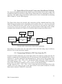
6.1.2 Connection Block Diagram
LAN (Common carrier Router) ESS
6.1.3 Connection Method
In the communication terminal part shown in subsection 6.4, plug the RJ45 LAN Cable
between the LAN terminal and the router.
6.2 Smart Meter Connection
6.2.1 D0 Interface
6.2.1.1 Components
6.2.1.1.1 D0 to RS 232 cable (Not provided in the product)
6.2.1.1.1.1 Cable name
KMK111RS232 OPTICAL Probe
6.2.1.1.1.2 Manufacturer
Z Telemetri
www.probeformeters.com
6.2.1.1.2 Meter for D0 (Not provided in the product)
Refer to meter list in subsection 6.3
6.2.1.1.3 RS232 D-sub 9 pin straight type extension line
6.2.1.1.4 Cable length limit
The total length of D0 to RS232 Cable and the extension line is 10m or less
6.2.1.2 Connection block diagram
6.2.1.2.1 Two-way meter
The meter cable must be connected to the D0-A.
(Refer to communication terminal in 6.4.1)
6.2.1.2.2 On using One-way meter
35
ENG. Version 140818
Feed-in Meter Cable must be connected to the D0-A.
Purchase Meter Cable must be connected to the D0-B.
(Refer to communication terminal in 6.4.1)
6.2.2 S0 Interface
6.2.2.1 Components
6.2.2.1.1 S0 Meter
6.2.2.1.2 Connection line (Not provided in the product)
6.2.2.2 Connection terminal
A : 47.42 mm +/- 0.8 , B : 38.1mm +/- 0.5
6.2.2.3 Connection block diagram
6.2.2.3.1 Two-way meter
Feed-in 2 wire must be connected to the S0(A).
Purchase 2 wire must be connected to the S0(B).
36
ENG. Version 140818
6.2.2.3.2 One-way meter
Feed-in Meter Cable must be connected to the S0(A).
Purchase Meter Cable must be connected to the S0(B).
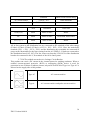
6.3 Recommended Meter List
No.
Company
1
2
EasyMeter
3
4
Hager
Vertriebsgesellschaft
5
EMH Metering
6
EMH Metering
7
EMH Metering
8
ISKRAEMECO GmbH
9
EMU Elektronik
Model
Interface
Direction
Q3DA1004
D0
Unidirection
Q3DA1024
D0
Bidirection
Q3DA1034
D0
Unidirection
EHZ363ZA
D0
Bidirection
eHZIW8E2A5L0EQ2P
ED300L W2E8-0NEL0-D2-0000002F50/Q2
eHZIW8E2A5WL0EQ2P
MT174-D2A52V12G12-KO
D0
Bidirection
D0
Bidirection
D0
Bidirection
D0
Bidirection
Professional 3/75
S0
Bidirection
※ The meters above are products supplied to Stark Company (Germany)
※ We recommend D0 bi-directional meters.
37
ENG. Version 140818
6.4 Communication Terminal
Communication terminal
6.5 Homepage
The customer purchasing this device can use the web browser (https://myess.samsungsdi.com)
or the smart phone to check operation status and various operation statistical information in
the house or remotely.
6.5.1 Service Terms
This service is provided only when the device is connected to the Internet, and specific
services can collect additional information only after approval from the customer.
6.5.2 Membership
To use the service, you must register for membership through the homepage. During
membership registration, the member’s information such as ID, password, name and the
address are collected and additional data can also be collected to provide statistical
information upon the customer’s approval.
6.5.3 Membership Withdrawal
For a customer who does not want to use the service, membership withdrawal is possible
through the personal information modification menu on the homepage.
6.5.4 Log-In
Log-in to the homepage through the ID and the password generated through membership
registration. If you are not logged in, normal service use is not possible.
Also, if a log-in ID error or a password error occurs five consecutive times, access is blocked
for 10 minutes for security, and access permitted afterwards, therefore, please take care.
38
ENG. Version 140818
Log-in Page
6.5.5 Password Initialization
For a customer who forgets their password during use, the password initialization menu can
be used on the homepage to initialize the password. In the log-in page, select the “Forgot
your id or password?” menu, and when the customer confirms the ID and the e-mail address
filled in during the membership registration, the initialized password is sent to the registered
e-mail address.
Password initialization screen
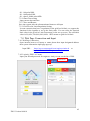
6.5.6 How to Use the Service
After completing log-in, normal service use is possible. This service currently provides
menus of monitoring, consumption report, ESS report, ESS forecast, and notice. (Enabled to
modify after further update.)
39
ENG. Version 140818
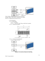
6.5.6.1 Monitoring
The operation status of the current product is indicated. The operation status of the product or
the customer power usage information, generation amount information can be checked in
real-time. Furthermore, event codes which occurred during run time can be checked on the
monitoring page. Details of the event codes can be checked by clicking the exclamation
marks which are popped up on the ESS icon. If internet is not available, customers cannot
check the event codes.
Monitoring page
6.5.6.2 Consumption Report
The household power usage information collected during smart meter linkage is provided. In
particular, information such as household type, size, and inhabiting manpower collected
according to the customer approval are used to provide various types of statistics and
comparative analysis data.
Consumption report page
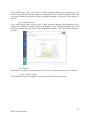
6.5.6.3 ESS Report
40
ENG. Version 140818
In the ESS Report page, various types of data generated through ESS operation can be
checked. The amount of energy charged or discharged can be checked through the ESS, and
other data comparison with solar energy production amount or the power sales amount is
possible.
6.5.6.4 ESS Forecast
In the ESS Report page, various types of data generated through ESS operation can be
checked. The amount of energy charged or discharged can be checked through the ESS, and
other data comparison with solar energy production amount or the power sales amount is
possible.
Forecast page
6.5.6.5 Notice
When there is an update or other changes in the service, the notice message can be checked.
6.5.6.6 S/W ver. check
The software version of the product can be checked on the monitoring page.
41
ENG. Version 140818
S/W ver
6.5.7 Mobile Service
For customers using Android or I-Phone, the product status can be easily checked on the
move through the smart phone. To use the mobile service, the customer must first register the
membership through the webpage and use the ID and the password to log-in and use the
service.
Mobile service
42
ENG. Version 140818
7 Input of Installation Information
Initial installation information needs to be input through the following procedure for
operation information of this system can be monitored appropriately on server.
7.1 Information Entering Administrator
The installer needs to input installation information by using laptop or smart phone
7.2 System Information Input Flow
1st Step : Direct Connection to PC -> Input Local Setting Value
2nd Step : Connection to Web Page -> Input Webpage Setting Value
7.3 Input PC Direct Connection and Local Setting Value
7.3.1 PC Direct Connection Flow and Input
System Off Status -> Insert Jumper Wire, Connect PC LAN cable
-> System AC on -> PC Direct Connection -> Input Setting Value
-> System off -> Remove Jumper Wire -> Connect Internet LAN Cable
7.3.2 Insert Jumper Wire (Not provided in the product)
7.3.3 LAN cable connection between PC and System
7.3.3.1 LAN Cable Type
- UTP cable/category 5E
- 1:1 direct cable
7.3.4 Connecting SIM(System Install Manager)
7.3.4.1 Connection URL
- http://17.91.23.196:8000
7.3.4.2 Connection Screen
43
ENG. Version 140818
7.3.5 Input Setting Value
7.3.5.1 S/N
Input value for shipment from factory, modification is not available
7.3.5.2 Region
Choose and input city for installation (within menu)
7.3.5.3 PV Install Value
Input installation capacity of each PV string
Input by typing in person
7.3.5.4 Sever IP & Port
Input as basic value.
Perform modification for modification issue only.
7.3.5.5 Smart Meter Selection
7.3.5.5.1 Meter Type
D0(Bi-Direction)
D0(Uni-Direction)
Select S0(Pulse Count)
7.3.5.5.2 D0 Meter model selection
Input when Meter Type is D0
D0-bi/feed-In :
Choose and input for inter-direction meter connection,
or choose one-direction feed-in type
D0-Purchase : choose one-direction purchase type
7.3.5.5.3 S0 Pulse Count per 1kWh
Input when Meter Type is S0
44
ENG. Version 140818
S0 : 100 pulse/kWh
S0 : 1000 pulse/kWh
S0 : choose 10000 pulse/kWh
7.3.5.6 Date/Time setting
Input current date and time
7.3.5.7 Save and Restart
Save into system after the aforementioned items are all input
7.3.5.8 Grid Feed in Limit Regulation Setting
In some countries that have a regulation for the grid feed in limit, we support the
function for the installer to set up the limit value. You can select the required
limit value in the [Feed in Limit Percentage] in the set up screen. The selectable
value is 0%,60%,70%,80%,90%,100%. 100% means no grid feed in limit.
7.4 Web Page Connection and Input
7.4.1 Web Page Connection
Open internet browser of laptop or smart phone then input designated address
then system information input page pops up.
Input URL :
https://myess.samsungsdi.com/engineer/main.do
https://112.106.12.149/engineer/main.do
or
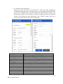
7.4.2 Login & “ESS List” menu
Input your ID and password for engineers. And you can see the list of ESS.
Main menu
45
ENG. Version 140818
7.4.3 Add new ESS Information
Click main menu and select “Add New ESS”. And input ESS information,
installation information and owner information. The data input include ESS UID,
service date, installation date, installer information, phone number, address, city
information, national code and these can differ according to product model and
version. After finished to input information, click “Submit” button. And if it is
saved successfully, you can see a success message.
Information
Serial No.
Device Type
Battery No.
Product Model
Capacity
Building Type
Building Name
Country
City
Address1
Address2
Utility Name
Tariff Name
Installer Name
Description
Write serial number of ESS
Select a type of ESS, e.g.)AIO is RES
Write serial number of battery
Write model code of ESS e.g.) AIO is ELSR362-00001
Write battery capacity, e.g.) AIO is 3.6
Select a type of building
Write building’s name e.g.) JACK’s HOME
Select a country
Select a city which ESS is located
Write an address of location
Write an address of location
Select an utility for the customer
Select a tariff for the customer
Write installer’s name or company name
46
ENG. Version 140818
Installer Contact
Installation Company
Installation Date
Remark
Owner Name
Owner Contact
Owner Address
Write install’s contact or company contact
Write installer’s company name
Select an installation date
Write a something important to remark
Write owner’s name
Write owner’s contact
Write owner’s address
7.4.4 Check current state of ESS
Click main menu and select “ESS list”. And click “Search” menu. If you input
search keywords and click “Search” button, you can see current status of ESS
47
ENG. Version 140818
8 Operation Test
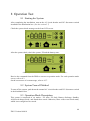
8.1 Starting the System
After completing the installation, turn on the AC circuit breaker and DC disconnect switch
installed in the distribution box. (See the section 5.7)
Check the system check message on the front LCD screen.
< Initial indication screen on power on >
After the system check, check the system, PV and the battery state.
<Standby state indication screen before the EMS command >
Receive the command from the EMS to convert to operation mode. For each operation mode
screen, refer to 8.3.
On the occurrence of event message, refer to 8.3.7.
8.2 System Turn-off Method
To turn-off the system, push down the manual AC circuit breaker and DC disconnect switch
in the distribution box.
8.3 Operation Mode Description
This system is composed of six modes - PV Auto, PV Only, Battery discharge, Standby,
A/S(forced charge) mode, and Stand-alone mode. Otherwise, there exists event check status,
which is not categorized as a mode.
48
ENG. Version 140818
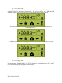
8.3.1 PV-Auto Mode
Solar energy generation is possible and battery charge-discharge is possible. The solar energy
generation power is charged or discharged to the battery through the EMS decision.
Maximum 4.6kW or less can be sent to the LOAD and the electric power system.
< Indication screen_1: Solar energy generation (Large), battery charge, home use, sell
remaining amount >
< Indication screen_2: Solar energy generation (small), battery discharge, Home use, buy
shortage amount>
< Indication screen_3:
Solar energy generation, Battery standby, Home use, sell remaining amount >
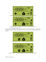
8.3.2 PV-Only Mode
This is the state enabled for solar energy generation. However, the battery charge-discharge
does not operate. Maximum 4.6kW or less of solar energy generation power can be sent to
the LOAD and the system through the EMS decision.
49
ENG. Version 140818
< Indication screen_1: Solar energy generation, Sell remaining amount >
< Indication screen_2: Solar energy generation, Buy shortage amount >
8.3.3 Battery-Discharge Mode
This is the state of having no solar energy generation. Only battery discharge is possible. By
the EMS decision, the battery discharge power can be sent maximum 2kW or less only to the
LOAD.
< Indication screen_1: Battery discharge, Home use >
< Indication screen_2: Battery discharge, Home use, Buy shortage amount >
50
ENG. Version 140818
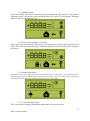
8.3.4 Standby Mode
This is the standby state before converting to the operation mode (PV Auto, PV Only, Battery
discharge mode). Conversion to the operation mode (PV Auto, PV Only, Battery discharge
mode) is made by the EMS decision.
< Indication screen on Standby Mode >
8.3.5 Forced-Charge Mode (A/S mode)
This is the forced charge mode of the battery in system check. (Solar energy generation is not
used.) This is the state where the power continuously flows from the electric power system to
the battery.
< Indication screen on Forced charged Mode >
8.3.6 Stand-Alone Mode
When the All in One is disconnected from the smart meter or the power conversion system is
disconnected from the EMS(energy management system), the All in One system enters into
the Stand-Alone Mode. The system operates in a PV- only mode.
< Indication screen on stand-alone mode >
8.3.7 Event Checking Status
This is the mode of stopping and standby generation on event occurrence.
51
ENG. Version 140818
<Indication screen_1 : event occurrence, Grid RMS over current protection>
<Indication screen_2 : event occurrence, DC link over voltage protection>
<Indication screen_3 : event occurrence, PV string1 reverse connection protection>
<Indication screen_4 : event occurrence, PV string2 reverse connection protection>
52
ENG. Version 140818
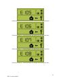
<Indication screen_5 : event occurrence, PV string1 over voltage protection>
<Indication screen_6 : event occurrence, PV string1 over current protection>
<Indication screen_7 : event occurrence, PV string2 over voltage protection>
<Indication screen_8 : event occurrence, PV string2 over current protection>
53
ENG. Version 140818
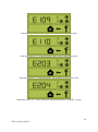
<Indication screen_9 : event occurrence, BATT over voltage protection>
<Indication screen_10 : event occurrence, BATT over current protection>
<Indication screen_11 : event occurrence, On sequence INV DC link event>
<Indication screen_12 : event occurrence, On sequence BATT V & BATT I event>
54
ENG. Version 140818
<Indication screen_13 : event occurrence, Normal INV DC link event>
<Indication screen_14 : event occurrence, Normal BATT V & BATT I & BDC DC link
event>
<Indication screen_15 : event occurrence, On sequence INV DC link event>
<Indication screen_16 : event occurrence, Normal INV DC link & PV I event>
55
ENG. Version 140818
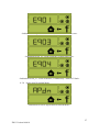
<Indication screen_17 : event occurrence, Temp protection>
<Indication screen_18 : event occurrence, Over Current Tripzone>
<Indication screen_19 : event occurrence, temp sensor>
<Indication screen_20 : event occurrence, PV common>
56
ENG. Version 140818
<Indication screen_21 : event occurrence, SPI communication event>
<Indication screen_22 : event occurrence, Single fault event>
<Indication screen_23 : event occurrence, Continuously 3 times PCS fault>
8.3.8 Application Download Mode
<Indication screen on Application Download Mode >
57
ENG. Version 140818
9 Problem confirmation
Checking event codes are available in the website (https://myess.samsungsdi.com). If internet
is not available, customers cannot check the event codes.
9.1 General Events
The general event is composed of warning and protection. The warning level events do not
affect the change in the product mode, and are automatically restored when solving the
problem. In this case, problem solving is enabled according to the change in the time and
operation status / condition.
On protection level event occurrence, the system stops, and is automatically restored when
solving the problem. In this case, problem solving is enabled according to the change in the
time and operation status / condition.
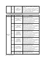
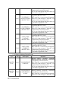
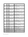
9.1.1 PCS General Events (Warnings)
Type
Code
Description
Measures
Occurs below the standard level of system
voltage.
This is the overall voltage-current warning
GRID UNDER
E001
message, with no special change in the
VOLTAGE
sequence.
The warning message disappears when
converted to the normal state.
Occurs above the standard level of system
voltage.
GRID OVER
This is the overall voltage-current warning
E002
VOLTAGE
message, with no special change in the
sequence. The warning message disappears
when converted to the normal state.
Occurs below the standard level of battery
energy voltage.
WARNIN
BATT UNDER
This is the overall voltage-current warning
G
E003
VOLTAGE
message, with no special change in the
sequence. The warning message disappears
when converted to the normal state.
Occurs above the standard level of battery
energy voltage.
BATT OVER
This is the overall voltage-current warning
E004
VOLTAGE
message, with no special change in the
sequence. The warning message disappears
when converted to the normal state.
Occurs when the Fan operation is
abnormal.
This is the overall Fan warning message,
E005
FAN WARNING
with no special change in the sequence.
The warning message disappears when
converted to the normal state.
58
ENG. Version 140818
E006
BATT
CONNECTION
WARNING
Occurs when the battery connection is
abnormal.
This is the connection warning message,
with no special change in the sequence.
The warning message disappears when
converted to the normal state.
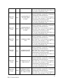
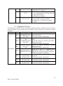
9.1.2 PCS General Events (Protection)
Type
Code
Description
Measures
The operation mode is terminated in most
significant PROTECTION
GRID RMS OVER Wait until the event message disappears.
E101
CURRENT
After the event message is removed, it is
PROTECTION
automatically restored to normal.
If it is not removed until the time limit, it is
converted to significant event.
The operation mode is terminated in most
significant PROTECTION
DC LINK OVER
Wait until the event message disappears.
E102
VOLTAGE
After the event message is removed, it is
PROTECTION
automatically restored to normal.
If it is not removed until the time limit, it is
converted to significant event.
The operation mode is terminated in most
significant PROTECTION
PV STRING1
Wait until the event message disappears.
REVERSE
E103
After the event message is removed, it is
CONNECTION
automatically restored to normal.
PROTEC
PROTECTION
If it is not removed until the time limit, it is
TION
converted to significant event.
The operation mode is terminated in most
significant PROTECTION
PV STRING2
Wait until the event message disappears.
REVERSE
E104
After the event message is removed, it is
CONNECTION
automatically restored to normal.
PROTECTION
If it is not removed until the time limit, it is
converted to significant event.
The operation mode is terminated in most
significant PROTECTION
PV STRING1
Wait until the event message disappears.
E105
OVER VOLTAGE After the event message is removed, it is
PROTECTION
automatically restored to normal.
If it is not removed until the time limit, it is
converted to significant event.
PV STRING1
The operation mode is terminated in most
E106
OVER CURRENT significant PROTECTION
PROTECTION
Wait until the event message disappears.
59
ENG. Version 140818
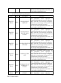
E107
PV STRING2
OVER VOLTAGE
PROTECTION
E108
PV STRING2
OVER CURRENT
PROTECTION
E109
BATT OVER
VOLTAGE
PROTECTION
E110
BATT OVER
CURRENT
PROTECTION
After the event message is removed, it is
automatically restored to normal.
If it is not removed until the time limit, it is
converted to significant event.
The operation mode is terminated in most
significant PROTECTION
Wait until the event message disappears.
After the event message is removed, it is
automatically restored to normal.
If it is not removed until the time limit, it is
converted to significant event.
The operation mode is terminated in most
significant PROTECTION
Wait until the event message disappears.
After the event message is removed, it is
automatically restored to normal.
If it is not removed until the time limit, it is
converted to significant event.
The operation mode is terminated in most
significant PROTECTION
Wait until the event message disappears.
After the event message is removed, it is
automatically restored to normal.
If it is not removed until the time limit, it is
converted to significant event.
The operation mode is terminated in most
significant PROTECTION
Wait until the event message disappears.
After the event message is removed, it is
automatically restored to normal.
If it is not removed until the time limit, it is
converted to significant event.
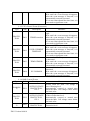
9.1.3 Battery Discharge General Events
Type
Code
Description
Measures
During Battery Discharge operation,
Battery Discharge operation is terminated
through the protection function.
PROTEC
ON SEQUENCE
Wait until the event message disappears.
E201
TION
GRID OFF
After the event message is removed, it is
automatically restored to normal.
If it is not removed until the time limit, it is
converted to significant event.
During Battery Discharge operation,
ON SEQUENCE
Battery Discharge operation is terminated
PROTEC
E202
BATT STATUS
through the protection function.
TION
EVENT
Wait until the event message disappears.
After the event message is removed, it is
60
ENG. Version 140818
E203
ON SEQUENCE
INV DC LINK
EVENT
PROTEC
TION
E204
ON SEQUENCE
BATT V & BATT I
EVENT
PROTEC
TION
E0205
NORMAL GRID
OFF
PROTEC
TION
E206
NORMAL BATT
STATUS EVENT
PROTEC
TION
E207
NORMAL INV DC
LINK EVENT
E208
NORMAL BATT V
& BATT I & BDC
DC LINK EVENT
PROTEC
TION
PROTEC
TION
automatically restored to normal.
If it is not removed until the time limit, it is
converted to significant event.
During Battery Discharge operation,
Battery Discharge operation is terminated
through the protection function.
Wait until the event message disappears.
After the event message is removed, it is
61
ENG. Version 140818
automatically restored to normal.
If it is not removed until the time limit, it is
converted to significant event.
9.1.4 PV General Events (Protection)
Type
Code
Description
PROTEC
TION
E301
PROTEC
TION
E302
PROTEC
TION
E303
PROTEC
TION
E304
PROTEC
TION
E305
PROTEC
TION
E306
Measures
During PV generation mode operation, the
PV generation mode operation is
terminated through the protection function.
ON SEQUENCE
Wait until the event message disappears.
GRID OFF
After the event message is removed, it is
automatically restored to normal.
If it is not removed until the time limit, it is
converted to significant event.
During PV generation mode operation, the
PV generation mode operation is
terminated through the protection function.
ON SEQUENCE
Wait until the event message disappears.
INV DC LINK
After the event message is removed, it is
EVENT
automatically restored to normal.
If it is not removed until the time limit, it is
converted to significant event.
During PV generation mode operation, the
PV generation mode operation is
terminated through the protection function.
ON SEQUENCE PV Wait until the event message disappears.
V EVENT
After the event message is removed, it is
automatically restored to normal.
If it is not removed until the time limit, it is
converted to significant event.
During PV generation mode operation, the
PV generation mode operation is
terminated through the protection function.
NORMAL GRID
Wait until the event message disappears.
OFF
After the event message is removed, it is
automatically restored to normal.
If it is not removed until the time limit, it is
converted to significant event.
During PV generation mode operation, the
PV generation mode operation is
terminated through the protection function.
NORMAL INV DC
Wait until the event message disappears.
LINK & PV I
After the event message is removed, it is
EVENT
automatically restored to normal.
If it is not removed until the time limit, it is
converted to significant event.
NORMAL PV V
During PV generation mode operation, the
EVENT
PV generation mode operation is
62
ENG. Version 140818
terminated through the protection function.
Wait until the event message disappears.
After the event message is removed, it is
automatically restored to normal.
If it is not removed until the time limit, it is
converted to significant event.
9.1.5 ETC General Events (Protection)
Type
Code
Description
Measures
Occurs when the switch temperature is
high.
Wait until the event message disappears.
PROTEC
E401
TEMP Protection
After the event message is removed, it is
TION
automatically restored to normal.
If it is not removed until the time limit, it is
converted to significant event.
Occurs on PCS hardware protection.
Wait until the event message disappears.
PROTEC
OVER CURRENT After the event message is removed, it is
E402
TION
TRIPZONE
automatically restored to normal.
If it is not removed until the time limit, it is
converted to significant event.
Occurs when the Temp sensor connection
is abnormal.
PROTEC
E403
TEMP SENSOR
Wait until the event message disappears.
TION
After the event message is removed, it is
automatically restored to normal.
Occurs when the PV common states is
abnormal.
PROTEC
E404
PV COMMON
Wait until the event message disappears.
TION
After the event message is removed, it is
automatically restored to normal.
9.1.6 BMS General Events
Type
Code
Description
WARNIN
G
E501
OVER VOLTAGE
PROTECTIONCELL
PROTEC
TION
E502
OVER VOLTAGE
PROTECTIONCELL
WARNIN
G
E503
UNDER VOLTAGE
PROTECTION-
Measures
Occurs when the Max. cell voltage is
above Warning level
Automatically restored to normal state
when the Max. cell voltage comes below
the limit value
System stops when the Max. Cell voltage
is above Protection level.
Automatically restored to normal state
when the Max. Cell voltage comes below
the limit value
Occurs when the Min. cell voltage is below
Protection level.
63
ENG. Version 140818
CELL
PROTEC
TION
E504
UNDER VOLTAGE
PROTECTIONCELL
WARNIN
G
E505
OVER TEMP.
PROTECTIONCELL
PROTEC
TION
E506
OVER TEMP.
PROTECTIONCELL
WARNIN
G
E507
UNDER TEMP.
PROTECTIONCELL
PROTEC
TION
E508
UNDER TEMP.
PROTECTIONCELL
WARNIN
G
E509
CELL VOLTAGE
IMBALANCE
PROTECTION
PROTEC
TION
E510
CELL VOLTAGE
IMBALANCE
PROTECTION
WARNIN
G
E511
AFE
INITIALIZATION
PROTEC
TION
WARNIN
G
PROTEC
TION
E512
E513
E514
AFE
INITIALIZATION
CELL TEMP
SENSOR 1EA
CELL TEMP
SENSOR 2EA
Automatically restored to normal state
when the Min. Cell voltage goes above the
limit value
System stops when the Min. cell voltage is
below Protection level.
Automatically restored to normal state
when the Min. Cell voltage goes above the
limit value
Occurs when the Max. Cell temperature is
above Protection level.
Automatically restored to normal state
when the Max. Cell temperature comes
below the limit value
System stops when the Max. Cell
temperature is above Protection level.
Automatically restored to normal state
when the Max. Cell temperature comes
below the limit value
Occurs when the Min. cell temperature is
below Protection level.
Automatically restored to normal state
when the Min. Cell temperature goes
above the limit value
System stops when the Min. cell
temperature is below Protection level.
Automatically restored to normal state
when the Min. Cell temperature goes
above the limit value
Occurs when the imbalance of the Cell
voltage is above limit value
Restored to normal state when the
imbalance of the Cell voltage is below
limit value
Occurs when the imbalance of the Cell
voltage is above limit value
Restored to normal state when the
imbalance of the Cell voltage is below
limit value
AFE initialization failure
Restored to normal mode on AFE
initialization success
AFE communication failure
Occurs above the standard level of Battery
cell temp.
Occurs above the standard level of Battery
cell temp.
64
ENG. Version 140818
9.1.7 EMS/Communication Events
Type
Code
Description
WARNING
E601
PCS CAN EVENT
Measures
WARNING
E602
ETHERNET EVENT
WARNING
E603
SMART METER
EVENT
9.1.8 Single Fault Events
Type
Code
Description
WARNING
GRID UNDER
VOLTAGE FAULT
E702
GRID OVER VOLTAGE
FAULT
E703
GRID UNDER
FREQUENCY FAULT
E704
GRID OVER
FREQUENCY FAULT
E705
GRID TEN MINUTE
AVERAGE FAULT
E706
RCMU FAULT
PV INSULATION
FAULT
Disconnect and reconnect the LAN.
Turn off and restart the router
Make sure that the DHCP server
function of router is activated.
Turn off and restart the system
Make sure that the Meter device is
properly selected.
Disconnect and reconnect the D0 cable.
Turn off and restart the system
Measures
E701
E708
Turn off and restart the system
Reconnect the communication line
between the EMS board and the DSP
board.
The operation mode is terminated when
power system event occurs. Restart 1
minute after electric power system event
settled.
The operation mode is terminated when
power system event occurs. Restart 1
minute after electric power system event
settled.
The operation mode is terminated when
power system event occurs. Restart 1
minute after electric power system event
settled.
The operation mode is terminated when
power system event occurs. Restart 1
minute after electric power system event
settled.
The operation mode is terminated when
power system event occurs. Restart 1
minute after electric power system event
settled.
Turn off system power when the level of
leakage current is over standard level.
Check leakage current level then restart
or turn off for the level below standard
and problem respectively.
OFF Turn off system power if PV
INSULATION RESISTANCE is of
65
ENG. Version 140818
E709
ANTI ISLANDING
FAULT
E710
FUNCTIONAL
SAFETY FAULT
standard level.
Restart after 3 minutes
In case of electric power system black
out, it automatically detects the state and
turns off All in One.
Restart after 3 minutes
Occur in case of mismatching between
the two MCU measuring values
Restart after 3 minutes if no problem
found
9.2 Significant Events
On significant event, the system is basically stopped operation, installer must be contacted,
and the problem must be solved by the installer for the system to be restored to normal
operation.
Type
Code
Description
Measures
SPI
Occurs on internal non-communication
E901
COMMUNICATIO between the PCS.
N EVENT
Contact the installer immediately.
Occurs on non-communication with the
CAN
EMS.
E902
COMMUNICATIO All in One System is operation converted to
N EVENT
Stand Alone mode.
Contact the installer immediately.
Occurs on system connection standard
SINGLE FAULT
E903
single fault over.
EVENT
Contact the installer immediately.
Significant
When PCS FAULT is occurred three
CONTINUOUSLY 3 consecutive times, PCS HARD FAIL is
E904
TIMES PCS FAULT judged to be occurred to stop the operation.
Contact the installer immediately.
PV CROSS
Occurs when the PV GND is crossE905
CONNECTION
connected.
Permanent Fail
Contact the installer immediately.
Cell Over Voltage
Exceeding Cell Max voltage
E906
Permanent Fail
Contact the installer immediately.
Cell Under Voltage Abnormal decrease in Cell Min voltage
E907
Permanent Fail
Contact the installer immediately.
66
ENG. Version 140818
10 Maintenance
10.1 Fan and Cover Cleaning
Clean the fan according to the following procedures. It is recommended to clean the fan every
six months.
Turn off the AC circuit breaker and DC disconnect switch in the distribution box and separate
the Photovoltaic MC4 connector from the connector part located on the side of the 3.6kWh
All in One.
Photovoltaic MC4 connector separation
Separate the side cover. Do not separate the front case cover.
After separating the cover, clean with smooth brush, paint brush or wet cloth.
Separate the connector of the fan.
Separate the fan.
Clean the fan with smooth brush or wet cloth.
Notice!
Use of compressed air may damage the fan.
In cleaning the fan, do not use compressed air, because it may
damage the fan.
After cleaning, assemble all components in reverse order.
67
ENG. Version 140818
10.2 Various Components Check and Exchange
10.2.1 Fuse Check
Check every six months and on device failure.
Do not perform Fuse Check when the device is operating.
Perform after turning off the DC disconnect switch and the AC circuit breaker.
Measure both ends of the Inverter PBA (Specify in code when numbering the code in the
future) F3, BDC PBA (Specify in code when numbering the code in the future) JF1 to check
the resistance value.
If the resistance value is open state (Mega ohms or Infinite value), perform PBA exchange.
10.2.2 Input / Output Terminal Check
Perform the check every six months or on device failure.
Perform the input / output terminal check after turning off the AC circuit breaker and DC
disconnect switch.
Do not perform when the device is operating.
Measure the input / output terminal with a multi-meter.
PV1 input (Specify in code when numbering the code in the future): CN13, CN14
PV2 input (Specify in code when numbering the code in the future): CN13, CN14
Battery input: CN17, CN27
AC output: CN1, CN4
If the resistance value is short state (close to 0), perform PBA exchange.
10.2.3 DC Link Check
Perform the check every six months or on device failure.
Perform DC link check after turning off the AC circuit breaker and DC disconnect switch.
Measure both ends of the DC link PBA (Specify in code when numbering the code in the
future) CN1, CN2 with a multi-meter to check the resistance value.
If the resistance value is short state, perform PBA exchange.
10.2.4 FAN Operation Check
Perform the check every six months or on device failure.
Check the FAN operation frequently. In failure, it can cause fatal damage to the device.
Perform PV Auto Mode to check whether both fans are operating properly.
In the case of failure, contact the installer.
10.3 Battery Maintenance
It is recommended to perform battery maintenance check every six months.
CAUTION!
All works or service on the ESS and electrical connections must be
supervised by personnel knowledgeable about batteries and the required
precautions.
When replacing battery trays, replace an old one with the same type and
number of batteries or battery packs (check the type label or serial
numbers/model numbers on battery trays).
68
ENG. Version 140818
Standby for 40 minutes for complete discharge within the system before
testing electrical parts inside the system!
CAUTION!
Do not dispose of batteries in a fire. The batteries may explode.
CAUTION!
Do not open or damage batteries. Released electrolyte is harmful to the skin
and eyes. It may be toxic.
CAUTION!
A battery can present a risk of electrical shock and high short-circuit
current. The following precautions should be observed when working on
batteries.
Remove watches, rings, or other metal objects.
Use tools with insulated handles.
Wear rubber gloves, eye protection glasses and boots when working on the
battery systems.
Do not lay tools or metal parts on top of batteries.
Disconnect charging source prior to connecting or disconnecting battery
terminals.
Determine if battery is inadvertently grounded. If inadvertently grounded,
remove source from ground. Contact with any part of a grounded battery
can result in electrical shock. The likelihood of such shock can be reduced
if such grounds are removed during installation and maintenance
(applicable to equipment and remote battery supplies not having a grounded
supply circuit).
10.3.1 Battery Problem Check
On checking the event message (as noted in Chapter 9), check whether it is battery system
significant event (subsection 9.2 significant event E901~E910).
If it is significant event, contact the installer or the maintenance personnel.
If it is significant event message related to the failure, exchange the battery. However, battery
exchange is permitted only to the qualified person.
The battery exchange procedure is as described in 10.3.2.
10.3.2 Battery Exchange Procedure
Check whether there is main body and external electrical / communication connection line to
be removed.
For the electric connection of the main body, block the AC circuit breaker and DC disconnect
switch in the distribution box to remove the power.
For the MC4 connector connected to the Photovoltaic source, separate the male terminal and
the female terminal.
Separate the AC cable connected to the terminal block in the AC line.
Remove the LAN communication cable.
For the complete electrical discharge of the main system, standby for 40 minutes. Remove the
front case cover of the enclosure as described in Chapter 5.
69
ENG. Version 140818
Separate the battery electric connection connector (BATT-A: Connector on the BDC side,
BATT-B: Connector on the battery side).
Separate the battery signal line (4 signal connectors).
Lay the main body down. Lay it so that the tray knob is visible. Work with at least two
persons (Weight over 95 kg).
Unfasten the screw on the battery tray to separate from the main body.
Lift the battery tray for separation.
Place the main body and the battery tray on the packing box. This process is the reverse order
of the installation process.
10.4 Replaceable Parts Listings
The list of parts replaceable for maintenance of this system is shown in the table below. For
other parts, please refer to the application notes linked on the website of SAMSUNG SDI, or
contact the installer or the service center.
No.
1
2
Part name
Li-Ion Battery Tray
PV connector
3
4
Fan1
Fan2
Manufacturer
SAMSUNG SDI
Muli-Contact AG c/o Stäubli
Group
Minebia manufacturing company
Minebia manufacturing company
Part number
PV STICK
4710KL-04W-B59-E00
4710KL-04W-B59-E00
10.4.1 Li-Ion Battery Tray
The Li-Ion battery module can be replaced in case of failure. The 3.6kWh System uses a
battery tray consisting of a 2-battery module manufactured by SAMSUNG SDI. When it is
needed to replace the battery module, please contact SAMSUNG SDI with the item name and
the serial number of the 3.6kWh All in One System.
Li_Ion Battery tray manufactured by SAMSUNG SDI
10.4.2
PV Connector
The PV connector can be replaced in case of damage. The PV connector used in the 3.6kWh
All in One System consists of PV stick male/female parts manufactured by Multi-Contact AG
c/o Stäubli Group.
PV Connector manufactured by Multi-Contact AG c/o Stäubli Group
10.4.3
FAN 1 & FAN 2
In the All in One System, FAN1 and FAN2 provide air circulation for regulating system
temperature. The fans can be replaced when they end their life, or in case of failure. When a
70
ENG. Version 140818
fan fails, the installer or the maintenance personnel will identify its causes, and will replace it
in case of hardware failure. The replacement method will depend on the local maintenance
conditions. The manufacturer's name and the model number of the fan are Minebia
Manufacturing Company/DC FAN MOTOR/4710KL-04W-B59-E00. For further details,
please refer to the Maintenance Manual or contact SAMSUNG SDI Service. The contact
address is described in Chapter 13.
71
ENG. Version 140818
11 Technical Specifications
Rating
Units
PV input quantities:
Vmax PV(absolute maximum)
DC 550V
PV input operating voltage range
DC 125~500V
Maximum operating PV input current per string
DC 15A
Isc PV (absolute maximum)
DC 20A
Max. inverter backfeed current to the array
0A
AC output quantities:
Voltage (nominal or range)
AC 230V (184V ~ 264.5V)
Current (maximum continuous)
AC 25A
Current (inrush)
68.6A peak, 100us
Frequency (nominal or range)
50Hz (47.5Hz~51.5Hz)
Power (maximum continuous)
4600W or VA
Power factor ranger
0.95 ~ 1 ~ 0.95
Maximum output fault current
AC Current (peak/duration) :
420A/4ms
Maximum output overcurrent protection
AC 30A RMS
Harmonic distortion of output current
5%
(at THD<2%, PAC> 0.5 PACnom)
AC input quantities:
Voltage (nominal or range)
AC 230V (184V ~ 264.5V)
Current (maximum continuous)
AC 25A :
Current (inrush)
AC 68.6A peak, 100us
Frequency (nominal or range)
50Hz (47.5Hz~51.5Hz)
DC input (other than PV) quantities:
Battery Voltage (nominal or range)
DC 60 V(nominal) :
Range : 43~67V
Battery Current (nominal continuous)
DC 33.3A
Battery Current (max. continuous)
DC 46.5A
DC output (other than PV) quantities:
Battery Voltage (nominal or range)
DC 60 V(nominal) :
Range : 43~67V
Battery Current (nominal continuous)
DC 33.3A
Battery Current (max. continuous)
DC 46.5A
Other quantities:
Protective class(I, II, III)
Class I
Ingress protection (IP) rating per part 1
IP21
AC connection
1 phase
Operating temperature
-10~40° C
Storage temperature
Over voltage category
-20~60° C
III
72
ENG. Version 140818
Derating Curve
Power efficiency curve
73
ENG. Version 140818
Power efficiency curve
74
ENG. Version 140818
12 Disassembly
12.1 Disassembly
CAUTION
Risk of injury due to the heavy weight of the 3.6kWh All in One!
Moving the system should be done by at least two persons.
CAUTION
Lethal hazards caused by high voltages in the 3.6kWh All in One!
CAUTION
Lethal hazards caused by voltage spikes if battery’s positive and negative
terminals are shorted by conductive metals.
Standby for 40 minutes for complete discharge within the system.
CAUTION
When transporting the All in One system with packaged type, remove the
battery tray from the All in One system and transport it separately.
12.1.1 Electric Connection Removal
Push down the DC disconnect switch in the distribution box.
Push down the AC circuit breaker in the distribution box.
Stand by for 40 minutes to complete discharge within the system.
Remove the AC connection terminal in the 3.6kWh All in One main body.
Remove the PV connection terminal in the 3.6kWh All in One main body.
Remove the communication cable from the 3.6kWh All in One.
Remove the smart meter.
12.1.2 Disassembly of 3.6kWh All in One Main Body
Check whether there is main body and external electrical / communication connection line to
remove.
Remove the front case cover of the enclosure as shown in Chapter 5.
Separate the battery electrical connection connector (BATT-A: Connector on the system side,
BATT-B: Connector on the battery side).
Separate the battery signal line (4 lines)
Lay the main body down. Lay it so that the tray knob is visible. Work with at least two
persons (Overweight).
Unfasten the screw on the battery tray to separate from the main body.
Lift the battery tray for separation.
75
ENG. Version 140818
Place the main body and the battery tray on the packing box. This process is the reverse order
of the installation process.
12.2 Packaging
Pack in the original box of the 3.6kWh All in One if possible.
If not possible, pack considering the weight of minimum 95kg.
Also, the main body must go into the box completely.
12.3 Storage
Store 3.6kWh All One in temperature conditions above -20~60° C.
12.4 Disposal
If the battery or the product life has expired, the regulations for the disposal of electronic
products in that region must be followed, and if not, send to Samsung SDI. The address is
indicated in the contact (Chapter 13).
76
ENG. Version 140818
13 Contact
For technical problems or inquiries for usage, please contact the installation company.
To receive customer support, the following information is required.
Product type
Serial Number
Connected PV module type and number
Option equipment
Address : 85737 Oskar-Messter-Str. 29 Ismaning (Muenchen) Germany
E-Mail : [email protected]
77
ENG. Version 140818
14 Appendix
Samsung SDI Limited Warranty
Product Name: 3.6kwh All in One
I.
Product Warranty
1. Samsung SDI warrants that the Product1 will be free from defects in material
and workmanship under normal use in accordance with the applicable
Technical Specifications for the Product.
2. The warranty period of the Product (“Product Warranty Period”) is specified
as follows:
A. PCS : The warranty period shall be five (5) years from the Date of
Installation2
B. Battery & Enclosure : The warranty period shall be two (2) years from the
Date of Installation
3. In the event that the Product should fail to conform to the Technical
Specifications during the Product Warranty Period, Samsung SDI shall, at
Samsung SDI’s option: (i) repair the non-conforming or defective Product; or
(ii) provide Buyer3 with a replacement for the Product. Samsung SDI shall be
responsible for all reasonable costs of repair or replacement in connection
with such non-conforming or defective Product; provided that Buyer shall
bear the costs of removing the defective Product(s) and (re) installation of the
repaired or replaced Product.
II. Performance Guarantee
1. In addition to the Product Warranty, Samsung SDI guarantees performance
of the Product to be maintained at least sixty five percent (65%) of initial
battery’s capacity, provided that the usage of the Product shall have
complied with the Operating Conditions under specification for a period of
ten (10) years after the Installation Date , whichever occurs earlier
(“Performance Guarantee Period”). Also, Samsung SDI guarantees cycle life
of 6,000cycles at room temperature 25℃.
2. About Self Discharging Degradation, Samsung SDI guarantees 180days after
1
2
“Product” means the battery pack of Samsung SDI that consists of Battery, PCS, and the Enclosure.
“Date of Installation” To claim any warranty hereunder, Buyer must provide the date of installation. If Buyer is unable to
submit any proof of the Date of Installation, Samsung SDI will calculate the Product Warranty Period from the
manufacturing date which is written on the Product’s label.
3
“Buyer” means any individual or entity that directly purchases the Product from Samsung SDI.
78
ENG. Version 140818
ex-work.
III. Limitation of Warranty
1. The warranties set forth hereunder shall not apply to Products which, in
Samsung SDI’s absolute judgment have been subjected to: misuse, abuse,
neglect or accident; alteration, improper installation, application or removal
(including but not limited to any installation, application, repair, service or
removal by any party not authorized in writing by Samsung SDI); nonobservance of Samsung SDI’s installation, users and/or maintenance
instructions; repair or modifications by someone other than an approved
service technician of Samsung SDI; power failure surges, lightning, flood, fire,
accidental breakage or other events outside Samsung SDI’s control. Further,
no warranty shall apply to any damage caused by goods to which Samsung
SDI’s Products are incorporated or installed into, or used together with,
including any parts thereof.
2. Buyer shall promptly (but in any event within five (5) days after obtaining
notice or knowledge thereof) notify Samsung SDI of any defect or other
nonconformity with any of equipment warranties identified by Buyer by
delivering written notice to Samsung SDI of a warranty claim. Samsung SDI
shall promptly notify Buyer of any defect or other nonconformity with any of
the equipment warranties identified by Samsung SDI.
3. EXCEPT AS SPECIFIED ABOVE, ALL EXPRESS OR IMPLIED
CONDITIONS, REPRESENTATIONS, AND WARRANTIES INCLUDING,
WITHOUT LIMITATION, ANY IMPLIED WARRANTY OR CONDITION
OF MERCHANTABILITY, FITNESS FOR A PARTICULAR PURPOSE, NONINFRINGEMENT, SATISFACTORY QUALITY, NON-INTERFERENCE,
ACCURACY OF INFORMATIONAL CONTENT, OR ARISING FROM A
COURSE OF DEALING, LAW, USAGE, OR TRADE PRACTICE, ARE
HEREBY EXCLUDED TO THE EXTENT ALLOWED BY APPLICABLE LAW
AND ARE EXPRESSLY DISCLAIMED BY SAMSUNG SDI. TO THE
EXTENT AN IMPLIED WARRANTY CANNOT BE EXCLUDED, SUCH
WARRANTY IS LIMITED IN DURATION TO THE EXPRESS WARRANTY
PERIOD. THIS DISCLAIMER AND EXCLUSION SHALL APPLY EVEN IF
THE EXPRESS WARRANTY SET FORTH ABOVE FAILS OF ITS
ESSENTIAL PURPOSE.
4. IN NO EVENT WILL SAMSUNG SDI BE LIABLE FOR ANY COSTS OR
PROCUREMENT OF SUBSTITUTE GOODS OR SERVICES OR FOR ANY
CONSEQUENTIAL, SPECIAL, INCIDENTAL, INDIRECT, OR PUNITIVE
DAMAGES, INCLUDING WITHOUT LIMITATION LOST PROFITS,
WHETHER THE CLAIM IS BASED ON CONTRACT, TORT, STRICT
LIABILITY, OR ANY OTHER THEORY OF LAW OR EQUITY, EVEN IF
79
ENG. Version 140818
ADVISED OF THE POSSIBILITY OF SUCH DAMAGES. SAMSUNG SDI’S
LIABILITY FROM ANY CAUSE WHATSOEVER SHALL IN NO EVENT
EXCEED THE AMOUNT OF THE PURCHASE PRICE PAID BY BUYER TO
SAMSUNG SDI FOR SUCH PRODUCT GIVING RISE TO THE LIABILITY.
IV. Obtaining of Warranty Service
A)
The warranty provided hereunder is only applicable to the Buyer
who has purchased Products directly from Samsung SDI or from the
subsidiaries of Samsung SDI.
B)
The return of any Products will not be accepted unless prior written
authorization has been given by Samsung SDI. The written authorization
should contain the Product’s model name, a description of the defect and/or
failure, and the serial number located on the Products label attached to the
backside of the Products, and the Date of Installation.
C)
In the event Samsung SDI has discontinued the manufacture of the
Product in issue at the time the related warranty claim is accepted by
Samsung SDI. Samsung SDI may, at its sole option, replace it with a
different type of Product (of mutually agreed size, color, shape and/or
power) or refund the purchase price prorated by the days of the relevant
Warranty Period remaining.
V.
Contact
Address : 85737 Oskar-Messter-Str. 29 Ismaning (Muenchen) Germany
E-Mail : [email protected]
80
ENG. Version 140818