1
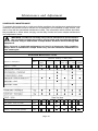
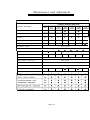
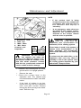
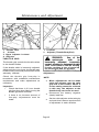
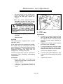
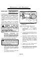
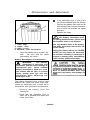
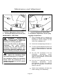
Maintenance and Adjustment
Contents
Scheduled
38
Maintenance
40
Side Panel ,
l
41
C o o l i n g S y s t e m
T h r o t t l e G r i p
44
C
h
47
C h a i n
48
.._........
51
Bearings
53
E
n
g
l
i
n
u
D r i v e
e
t
Brakes
Steering/Wheel
Front Suspension
O
c
i
46
54
Rear Suspension Adjustment
T
y
r
e
s
57
Battery................
62
Windscreen Cleaning
64
Fuses
.._....
65
Headlights - Daytona
66
58
Headlights - Speed Triple
68
R e a r
L i g h t
70
Licence Plate Light
70
Indicator Light . . . . . . . . . . . . . . . . .
70
Cleaning . . . . . . . . . . . . . . . . . . . . .
71
Page 37
Maintenance and Adjustment
SCHEDULED MAINTENANCE
To maintain the motorcycle in a safe and reliable condition, the maintenance and adjustments
outlined in this section must be carried out as specified in the schedule of daily checks, and
also in line with the scheduled maintenance chart. The information which follows describes
the procedures to follow when carrying out the daily checks and some simple maintenance
and adjustment items.
A
WARNING: In order to correctly carry out the maintenance items listed in
the scheduled maintenance chart, special tools and specialist knowledge
will be required. Only an authorised Triumph dealer will have this knowledge and
equipment.
Since incorrect or neglected maintenance can lead to a dangerous riding condition,
always have an authorised Triumph dealer carry out the scheduled maintenance of
this motorcycle.
Scheduled Maintenance Chart
Odometer Reading in Miles (Kms)
Operation Description
Every
Engine o i l - renew
500
(800)
24000
30000
12000
16000
6000
( 1 0 0 0 0 ) (20000) (30000) (40000) (50000)
l
0
0
0
0
0
Cooling system -check for leaks
Day
0
0
0
0
0
0
Fuel system -check for leaks
Day
0
0
l
0
0
0
Day
0
0
Steering - check for free operaton
0
l
Fuel Filter - renew
Page 38
0
0
0
0
Maintenance and Adjustment
I
Scheduled Maintenance Chart (Continued)
Operation Description
Headstock bearing -check/adjust
Headstock bearing - lubricate
Forks-check for leaks/smooth
operation
l
Day
l
l
Brake fluid
levels-check
l
Day
l
Brake fluid - renew
I
Brake hoses -renew
l
l
l
l
l
l
0
Every 2 years
Every 4 years
I
I
Brake light-check operation
Day
Brake pads - check wear levels
Day
1
I
l
l
I
l
l
I
l
I
l
Brake master cylinder - renew seals
Every 2 years
Brake calipers - renew seals
Every 2 years
Drive chain - lubricate
l
I
l
l
I
l
l
l
0
l
Every 200 miles (300 kms)
Drive chain -wear check
Drive chain slack - check/adjust
l
l
Fork o i l - renew
Every 500 miles (800 kms)
Day
l
Rear suspension - lubricate
l
0
l
3 years/24000 miles (40000 kms)
Page 39
Maintenance and Adjustment
A
WARNING: All maintenance
is vitally important and must
not be neglected.
Incorrect
maintenance or adjustment may
cause one or more parts of the
motorcycle to malfunction. A
motorcycle
malfunctioning
is
dangerous and may lead to an
accident.
Weather, terrain and geographical
location affects maintenance. The
maintenance schedule should be
adjusted to match the particular
environment in which the vehicle is
used and the demands of the
individual owner.
Triumph Motorcycles cannot accept
any responsibility for damage or
injury resulting from incorrect
maintenance or improper adjustment
carried out by the owner.
Since
incorrect or
neglected
maintenance can lead to a dangerous
riding condition, always have an
authorised Triumph dealer carry out
the scheduled maintenance of this
motorcycle.
SIDE PANEL
Side Panel Removal
l
l
.
l
l
Remove the seat(s).
Disconnect the battery, negative
(black) lead first.
Release the fixings as shown in the
diagram above.
Disconnect the rear light.
Lift and withdraw the side panel
assembly in a rearward direction.
Side Panel Refitting
l
l
l
Reverse the removal procedure with
the exception of the following.
Reconnect the battery positive (red)
lead first.
Tighten the panel fixings to 9 Nm.
Page 40
Maintenance and Adjustment
Oil Level Inspection
1. Sight Glass
2. Filler
3. Filler Plug
l
l
ENGINE OIL
I
In order for the engine, transmission, and
clutch to function correctly, maintain the
engine oil at the correct level, and change
the oil and oil filter in accordance with
scheduled maintenance requirements.
A
Stop engine, then wait for at least
10 minutes to allow the oil to settle.
The oil level is indicated by a sight
glass situated at the bottom of the
clutch cover on the right hand side of
the motorcycle. When the oil level is
correct, the level of oil should be
between the two lines marked on the
clutch cover to the right of the sight
glass.
NOTE:
WARNING:
Motorcycle
operation with insufficient,
deteriorated, or contaminated engine
oil will cause accelerated engine wear
and may result in engine or
transmission seizure. Seizure of the
engine or transmission may lead to
loss of control and an accident.
Page 41
The actual level is indicated when
the motorcycle is level and
upright, not on the side stand.
If the oil level is too low, remove the
plug situated in the upper rear side of
the clutch cover.
Add oil, a little at a time, until the oil
begins to show in the sight glass.
Then adjust to the correct level and
refit the plug.
Maintenance and Adjustment
With the motorcycle on level ground,
allow the oil to completely drain.
Unscrew and remove the oil filter
using the Triumph service tool
T3880310.
Discard the oil filter.
Apply a smear of clean engine oil to
the sealing ring of the new oil filter.
Fit the oil filter and tighten to 12 Nm.
1. Oil Drain Plug
2. Oil Filter
Fill the engine with new oil of the type
and grade listed in the specification
section.
Oil and Oil
Filter Change
A
After the oil has completely drained
out, fit a new sealing washer to the
engine drain plug. Fit and tighten the
plug to 25 Nm.
I
Start the engine and allow to idle.
WARNING:
Prolonged or
repeated contact with engine
oil can lead to skin dryness, irritation
and dermatitis. In addition, used
engine oil contains potentially
harmful contamination which can
cause cancer. Wear suitable clothing
and avoid skin contact.
The engine oil and filter must be replaced in
accordance with scheduled maintenance
requirements.
l
Warm up the engine thoroughly, and
then stop the engine.
Place an oil pan beneath the engine.
l
Remove the engine drain plug.
l
Page 4 2
Maintenance and Adjustment
l
Ensure that the oil pressure warning
light extinguishes shortly after
starting.
CAUTION: If the engine oil
!
pressure is too low, the low oil
A
pressure warning light will illuminate.
If this light stays on when the engine
is running,
stop the engine
immediately and investigate the
cause. Running the engine with low
oil pressure will cause engine
damage.
l
Stop the engine and check the oil
level. Adjust if necessary.
Disposal of Used Engine Oil
To protect the environment, do not pour oil
on the ground, down sewers or drains, or
into water courses. Dispose of used oil
sensibly. If in doubt contact your local
authority.
Triumph high
! CAUTION:
performance fuel injected
A
engines are designed to use semi or
fully synthetic 10W/40 motorcycle
engine oil which meets specification
API SH.
Do not add any chemical additives to
the engine oil. The engine oil also
lubricates the clutch and any
additives could cause the clutch to
slip.
Do not use mineral, vegetable,
non-detergent oil, castor based oils
or any oil not conforming to the
required specification. The use of
these oils may cause instant, severe
engine damage.
Ensure no foreign matter enters the
crankcase during an oil change or
top-up.
Page 43
Maintenance and Adjustment
COOLING
SYSTEM
To ensure efficient
engine
cooling,
check the coolant level each day before
riding the motorcycle, and top up the coolant
if the level is low.
Corrosion Inhibitors
To protect the cooling system from rust and
corrosion, the use of corrosion inhibitor
chemicals in the coolant is essential.
If coolant containing corrosion and rust
inhibitor chemicals is not used, the cooling
system will accumulate rust and scale in the
water jacket and radiator. This will block the
coolant passages, and considerably reduce
the efficiency of the cooling system.
A
WARNING:
Use coolant
mixture containing corrosion
inhibitors and anti-freeze suitable for
aluminium engines and radiators.
Always use the anti-freeze in
accordance with the instructions of
the manufacturer.
Coolant mixture which contains antifreeze and corrosion inhibitors
contains toxic chemicals which are
harmful to the human body. Never
swallow anti-freeze or any of the
motorcycle coolant.
Coolant Change
Have the coolant changed by an authorised
Triumph dealer in accordance with
scheduled maintenance requirements.
Radiator Hoses
Check the radiator hoses for cracks or
deterioration, and hose clips for tightness in
accordance with scheduled maintenance
requirements.
Have your authorised
Triumph dealer replace any defective items.
CAUTION: A permanent type
of antifreeze is installed in the
cooling system when the motorcycle
leaves the factory. It is coloured blue,
contains a 50% solution of ethylene
glycol, and has a freezing point of
-35°C (-31 *F
1
Radiator and Cooling Fan
Check the radiator fins for obstructions by
insects, leaves or mud. Clean off any
obstructions with a stream of low-pressure
water.
the fan. Contact with the rotating fan
A
CAUTION:
Using high
!
pressure water, such as from
a car wash facility, can damage the
radiator fins and impair the radiator’s
efficiency.
Do not obstruct or deflect airflow
through the radiator by installing
unauthorised accessories, either in
front of the radiator or behind the
cooling fan. Interference with the
radiator
airflow
can
cause
overheating, resulting in engine
damage.
Page 44
Maintenance and Adjustment
NOTE
l
l
1.
2.
3.
4.
Distilled water
CAUTION:
must be used with the
antifreeze (see specification for
antifreeze) in the cooling system.
A
PI
If hard water is used in the system, it
causes scale accumulation in the
water passages, and considerably
reduces the efficiency of the cooling
system.
A
WARNING: Do not remove
the radiator cap when the
engine is hot. When the engine is hot,
the coolant inside the radiator is hot
and also under pressure. Contact
with this hot, pressurised coolant will
cause scalds and skin damage.
l
l
l
l
In an emergency, water alone can
be added to the cooling system.
However, the coolant must be
returned to the correct mixture
ratio as soon as possible.
!
A
Expansion Tank
Tank Cap
‘MAX’ Mark
‘MN’ Mark
Coolant Level
Inspection
If the coolant level is being
checked because the coolant has
overheated, also check the level in
the radiator and top-up if
necessary.
If coolant must be added often, or the
expansion tank runs dry, there is
probably a leak in the system. Have
the cooling system inspected by your
authorised Triumph dealer.
Position the motorcycle on level
ground and in an upright position.
Remove the seat.
Check the coolant level in the
expansion tank. The coolant level
must be between the ‘MAX’ and ‘MIN’
marks.
If the level of coolant is too low,
remove the cap from the expansion
tank, and add coolant mixture
through the filler opening to the ‘MAX’
mark. Refit the cap.
Page 45
Maintenance and Adjustment
1. Throttle Grip
2 . 2-3mm
3. Upper Adjuster Locknut
4. Adjuster
1. Locknut
2. Adjuster (Throttle Body End)
THROTTLE GRIP
The throttle grip controls the throttle valves
in the throttle bodies.
If the throttle cable is incorrectly adjusted,
either too tight or too loose, the throttle may
be difficult to control and performance will be
adversely affected.
Check the throttle grip free-play in
accordance with scheduled maintenance
requirements and make adjustments as
necessary.
Inspection
l
l
Check that there is 2-3 mm throttle
grip free-play when lightly turning the
throttle grip back and forth.
If there is an incorrect amount of
free-play, adjustments must be
made.
cable could interfere with the throttle
function resulting in loss of control of
the motorcycle and an accident.
Adjustment
NOTE:
Minor adjustments can be made
using the adjuster near the twist
grip end of the throttle. Where a
correct setting cannot be achieved
in this way, the adjuster at the
throttle body end must be used.
Disconnect the battery negative
(black) lead first.
Set the cable adjuster at the twist grip
end such that it has an equal amount
of adjustment in each direction.
Page 46
Maintenance and Adjustment
l
l
Set the adjuster at the throttle body
end of the cable to give 2-3 mm of
play at the twist grip. Tighten the
locknut.
Make any minor adjustments as
necessary to give 2-3 mm of play
using the adjuster at the twist grip end
of the cable. Tighten the locknut.
A
WARNING: Ensure that both
the adjuster locknuts are
tightened. A loose throttle cable
adjuster could cause the throttle to
stick leading to loss of control and an
accident.
l
l
1. Lever
2. 0.4-0.8 mm
Reconnect the battery, positive (red)
lead first.
Adjustment
Refit the seat.
CLUTCH
The motorcycle is equipped with a cable
operated clutch.
If the clutch lever has excessive free-play,
the clutch may not disengage fully and
cause difficulty in changing gear and clutch
drag. Conversely, if the clutch lever has
insufficient free-play the clutch may not
engage fully, causing clutch slip.
Loosen the knurled locknut at the
lever end of the clutch cable and turn
the adjuster sleeve until the correct
amount of clutch lever free-play is
achieved.
Tighten the knurled locknut against
the clutch lever assembly.
If correct adjustment cannot be made
using the lever adjuster, use the cable
adjuster at the lower end of the cable.
Loosen the adjuster locknut.
Clutch lever free-play must be checked in
accordance with scheduled maintenance
requirements.
Turn the outer cable adjuster to give
0.4-0.8 mm of free-play at the clutch
lever.
Inspection
Tighten the locknut.
l
l
Check that there is 0.4-0.8 mm
clutch lever free-play as shown in the
diagram above.
If there is an incorrect amount 01
free-play, adjustments must be
made.
Page 47
Maintenance and Adjustment
For safety and to prevent excessive wear,
the drive chain must be checked, adjusted,
and lubricated in accordance with
scheduled maintenance requirements.
Checking, adjustment and lubrication must
be carried out more frequently for extreme
conditions such as salty or heavily gritted
roads.
If the chain is badly worn or incorrectly
adjusted (either too loose or too tight) the
chain could jump off the sprockets or break.
1. Maximum Movement Position
(35-40 mm)
Chain Free-movement Adjustment
sprockets could snag on the engine
sprocket or lock the rear wheel,
severely damaging the motorcycle
Never neglect chain maintenance.
NOTE:
l
Checking,
adjustment
and
lubrication of the drive chain must
be carried out with the motorcycle
set up on a paddock stand so that
the rear suspension hangs free.
Chain Free-movement Inspection
A
WARNING: To prevent risk of
injury from the motorcycle
falling during the inspection, ensure
that the motorcycle is stabilized and
secured on the stand.
l
l
Rotate the rear wheel to find the
position where the chain is tightest,
and measure the vertical movement
of the chain midway between the
sprockets.
chain
free-movement
If the
incorrect,
measurement
is
adjustments must be made as
follows:
Loosen the clamp bolt which secures
the rear hub/eccentric adjuster to the
swinging arm.
Using the ‘C’ spanner supplied in the
motorcycle tool kit, turn the rear
hub/eccentric adjuster (clockwise to
loosen, anti-clockwise to tighten)
until the drive chain is correctly
adjusted (35-40 mm of vertical
movement).
Tighten the rear hub/eccentric
adjuster clamp bolt to 55 Nm.
Rotate the rear wheel and repeat the
chain adjustment check. Re-adjust
if outside the 35-40 mm limit.
The vertical movement of the drive
chain must be 35-40 mm.
Puge 48
Maintenance and Adiustment
I
1. Measure Across 20 Links
2. Weight
1. Adjuster Clamp Bolt
2. ‘C’ Spanner
3. Eccentric Adjuster
l
A
WARNING: Operation of the
motorcycle with an insecure
rear hub/eccentric adjuster clamp
bolt may result in impaired stability
and handling of the motorcycle. This
impaired stability and handling may
lead to loss of control or an accident.
l
Check the rear brake effectiveness.
Chain Wear Inspection
Stretch the chain taut by hanging a
10-20 kg (20-40 lb) weight on the
chain.
.
Measure the length of 20 links on the
straight part of the chain from pin
centre of the 1 st pin to the centre of
the 21st pin. Since the chain may
wear unevenly, take measurements
at several places.
.
If the length exceeds the maximum
service limit of 319 mm, the chain
must be replaced.
A
the motorcycle is stabilized and
l
Remove the chain guards.
WARNING:
A chain that
breaks or jumps off the
sprockets could snag on the engine
sprocket or lock the rear wheel,
severely damaging the motorcycle
and causing loss of control and an
accident.
Page 49
Maintenance and Adjustment
.
If there is any irregularity, have the
drive chain and/or the sprockets
replaced by an authorised Triumph
dealer.
.
Replace the chain guard.
WORN TOOTH
WORN TOOTH
(ENGINE SPROCKET) (REAR SPROCKET)
w-w
NOTE:
l
Sprocket wear is exaggerated for
illustration.
The use of
WARNING:
non-approved chains may
result in a broken chain or may cause
the chain to jump off the sprockets.
Chain
Lubrication
,
Lubrication
necessary every 500 miles and also after
riding in wet weather, on wet roads, or any
time that the chain appears dry.
Use the special chain lubricant as
recommended in the specification section.
l
A
Use a genuine Triumph supplied
chain as specified in the Triumph
Parts Catalogue.
Never neglect chain maintenance and
always have chains installed by an
authorised Triumph dealer.
l
l
l
Apply lubricant to the sides of the
rollers. This will allow the oil to
penetrate to the chain rollers and
bushings. Also apply oil to the chain
‘0’ rings. Wipe off any excess oil.
If the chain is especially dirty, clean
first using paraffin and then apply oil
as mentioned above.
CAUTION:
Do not use a
!
power ‘jet’ wash to clean the
A
chain as this may cause damage to
the chain components.
Rotate the rear wheel and inspect the
drive chain for damaged rollers, and
loose pins and links.
Also inspect the sprockets for
unevenly or excessively worn or
damaged teeth.
Page 50
Maintenance and Adjustment
Disc Brake Fluid
Inspect the level of brake fluid in both
reservoirs and change the brake fluid in
accordance with scheduled maintenance
requirements. Use only DOT 4 fluid as
recommended in the specification section.
The brake fluid must also be changed if it
becomes, or is suspected of having become
contaminated with moisture or any other
contaminants.
A
1. Lining Thickness
2. 1.5 mm (0.06 in) Groove Thickness
BRAKES
Brake Wear Inspection
Brake pads must be inspected in
accordance with scheduled requirements
and replaced if worn to, or beyond the
minimum service thickness.
If the lining thickness of any pad (front or rear
brakes) is less than 1.5 mm (0.06 in), that is,
if the pad has worn down to the bottom of the
grooves, replace all the pads on the wheel.
Brake fluid is
WARNING:
hygroscopic which means it
will absorb moisture from the air.
Any absorbed moisture will greatly
reduce the boiling point of the brake
fluid causing a reduction in braking
efficiency.
Because of this, always replace brake
fluid in accordance with scheduled
maintenance requirements.
Always use new brake fluid from a
sealed container and never use fluid
from an unsealed container or from
one which has been previously
opened.
A
WARNING: Brake pads must
always be replaced as a wheel
set. At the front, where two calipers
are fitted on the same wheel, replace
all the brake pads in both calipers.
Replacing individual pads will reduce
braking efficiency and may cause an
accident.
Page 51
Do not mix different brands or grades
of brake fluid.
Check for fluid leakage around brake
fittings, seals and joints and also
check the brake hoses for splits,
deterioration and damage.
Always rectify any faults before
riding.
Failure to observe and act upon any of
these items may cause a dangerous
riding condition leading to loss of
control and an accident.
Maintenance and Adjustment
1. Upper Level, Front Brake
2. Lower Level, Front Brake
3. Safety Clip
1. Upper Level, Rear Brake
2. Lower Level, Rear Brake
Brake Fluid Level Inspection and
Adjustment
l
The brake fluid level in the reservoirs
must be kept between the upper and
lower level lines (reservoir held
horizontal).
l
At the rear, remove the side panel
assembly.
l
Remove the safety clip (front only).
.
Fill the reservoir to the upper level line
using new DOT 4 fluid from a sealed
container.
.
Refit the reservoir cap ensuring that
the diaphragm seal is correctly fitted.
l
Refit the safety clip.
l
At the rear, refit the side panels.
Brake Pad Wear Compensation
Disc and disc pad wear is automatically
compensated for and has no effect on the
brake lever or pedal action. There are no
parts that require adjustment on the front
and rear brakes.
A
WARNING: If there has been
an appreciable drop in the
level of the fluid in any fluid reservoir,
consult your authorised Triumph
dealer for advice before riding.
A
WARNING: If the brake lever
or pedal feels soft when it is
applied, or if the lever/pedal travel
becomes excessive, there may be air
in the brake lines or the brake may be
defective.
It is dangerous to operate the
motorcycle under such conditions
and remedial action must be taken by
your authorised Triumph dealer
before riding.
Riding with defective brakes may lead
to an accident.
Riding with defective brakes may lead
to an accident.
Page 52
Maintenance and Adjustment
Brake Light Switches
The brake light is activated independently
by either the front or rear brake. If the brake
light does not work when the front brake
lever is pulled, or the rear brake pedal
depressed, ask your authorised Triumph
dealer to investigate and rectify the fault.
A
WARNING:
Riding the
motorcycle with defective
brake lights is illegal and dangerous.
An accident causing injury to the rider
and other road users may result from
use of a motorcycle with defective
brake lights.
Inspecting the Steering for Free-Play
Inspection
STEERING/WHEEL BEARINGS
Steering Inspection
Position the motorcycle on level
ground, in an upright position.
Lubricate and inspect the condition of the
headstock (steering) bearings in
accordance with scheduled maintenance
requirements.
Remove the belly panel (where
fitted).
Raise the front wheel off the ground
and place a block beneath the engine
to support the motorcycle.
NOTE
.
Always inspect the wheel bearings
at the same time as the steering
bearings.
Hold the lower end of the front forks
and try to move them forward and
backward.
A
WARNING: To prevent risk of
injury from the motorcycle
falling during the inspection, ensure
that the motorcycle is stabilized and
secured on the support block.
Do not exert extreme force against
each wheel or rock each wheel
vigorously as this may cause the
motorcycle to become unstable or
cause injury by falling from its
support.
Ensure that the position of the
support block will not cause damage
to the oil lines beneath the sump.
Page 53
If any free-play can be detected, ask
your authorised Triumph dealer to
inspect and rectify any faults before
riding.
cause loss of motorcycle control and
l
Leaving the support in place, inspect
the wheel bearings as described
over.
Maintenance and Adjustment
Wheel Bearings inspection
FRONT SUSPENSION
If the wheel bearings in the front or rear
wheel allow play in the wheel hub, are noisy,
or if the wheel does not turn smoothly, have
your authorised Triumph dealer inspect the
wheel bearings.
All models are fitted with forks which are
adjustable for spring pre load, compression
damping and rebound damping.
The wheel bearings must be inspected at
the intervals specified in the scheduled
maintenance chart.
Front Fork Inspection
l
l
l
l
l
Gently rock the top of the front wheel
from side to side.
If any free-play can be detected, ask
your authorised Triumph dealer to
inspect and rectify any faults before
riding.
Reposition the lifting device and
repeat for the rear wheel.
A
WARNING: Operation with
worn or damaged wheel
bearings may cause impaired
handling and instability leading to an
accident.
If in doubt, have the
inspected
by
an
motorcycle
authorised Triumph dealer before
riding.
.
l
Examine each fork stanchion for any
sign of damage, scratching of the
slider surface, or for oil leaks.
If any damage or leakage is found
consult an authorised Triumph
dealer.
To check that the forks operate smoothly:
l
l
Position the motorcycle on level
ground.
While holding the handlebars and
applying the front brake, pump the
forks up and down several times.
NOTE:
l
l
The suspension movement will be
affected by adjustment settings.
If roughness or excessive
stiffness is detected, consult your
authorised Triumph dealer.
Remove the support and place the
motorcycle on the side stand.
Refit the belly panel (where fitted).
Page 54
Maintenance and Adjustment
* Number of adjuster turns out from the fully screwed in position.
NOTE:
This chart is only a guide. Setting requirements may vary for rider weight and personal
preferences. See the following pages for details of how to adjust your suspension.
Front Suspension Settings
The standard suspension settings provide a
comfortable ride and good handling
characteristics for general, solo riding. The
chart shows suggested settings for front and
rear suspension.
A
WARNING: Ensure that the
correct balance between front
and rear suspension is maintained.
could
Suspension
imbalance
handling
significantly
change
characteristics leading to loss of
control and an accident. Refer to the
chart above for further information or
consult your Triumph dealer.
setting on both forks. Settings which
affect handling resulting in loss of
NOTE:
The spring pm-load and rebound damping
adjusters are located in the top of each fork.
The compression damping adjuster is
located near the bottom of each fork,
adjacent to the wheel spindle.
Page 55
l
The setting figures above/over
are all measured as adjuster turns
out from the fully screwed in
position.
Maintenance and Adjustment
1. Spring Pre-load Adjuster
2. Rebound Damping Force Adjuster
3. Compression
Adjuster
Spring Pm-load Adjustment
NOTE:
l
The motorcycle is delivered from
the factory with the compression
damping set at position 1.
To change the spring pre-load, rotate the
adjuster clockwise (screw-in) to increase
pre-load, or anti-clockwise (screw-out) to
decrease pre-load.
Always set the
pre-load adjusters such that there are an
equal number of graduation lines visible on
both forks.
NOTE:
l
The motorcycle is delivered from
the factory with the spring
pre-load set on position 5.
Compression Damping Adjustment
To change the compression damping force
rotate the slotted adjuster clockwise
(screw-in) to increase, or anti-clockwise
(screw-out) to decrease.
Maximum damping force is obtained when
the adjuster is rotated fully clockwise
(screwed fully in).
Minimum damping force is obtained when
the adjuster is rotated fully anti-clockwise
(screwed fully out). Always count the turns
out from the screwed fully in position and set
both forks to the same setting.
Damping
Force
Rebound Damping Adjustment
To change the rebound damping force,
rotate the slotted adjuster clockwise
(screw-in) to increase, or anti-clockwise
(screw-out) to decrease. Always count the
turns out from the screwed fully in position
and set both forks to the same position.
Maximum damping force is obtained when
the adjuster is rotated fully clockwise
(screwed fully in).
Minimum damping force is obtained when
the adjuster is rotated fully anti-clockwise
(screwed fully out).
NOTE:
l
The motorcycle is delivered from
the factory with the rebound set at
position 1.
Page 56
Maintenance and Adjustment
1. Compression Damping Adjuster
1. Rebound Damping Adjuster
REAR SUSPENSION ADJUSTMENT
Compression Damping Adjustment
The rear suspension unit is adjustable for
both compression and rebound damping.
The compression damping adjuster is
situated on the rear suspension unit
reservoir.
Rebound Damping Adjustment
The rebound damping adjuster is situated at
the lower left hand end of the rear
suspension unit.
To adjust the rebound damping setting,
rotate the adjuster clockwise to increase
rebound damping and anti-clockwise to
decrease.
To adjust the compression damping setting,
rotate the slotted adjuster clockwise
(screw-in) to increase, or antiilockwise
(screw-out) to decrease.
NOTE:
l
NOTE
l
l
The settings are all measured as
the number of adjuster turns out
from the fully screwed in position.
The motorcycle is delivered from
the factory with the rebound
adjuster set to position 1.
The motorcycle is delivered from
the factory with the compression
damping set at 1.
A
WARNING: Rear suspension
unit spring pm-load is not
rider adjustable. Any attempt to
adjust the spring pre-load could
result in a dangerous riding condition
leading to loss of control and an
accident.
Page 57
Maintenance and Adjustment
Typical Tyre Marking
TYRES
This motorcycle
is equipped with
tubeless tyres, valves and wheel rims. Use
only tyres marked ‘TUBELESS’ and
tubeless valves on rims marked ‘SUITABLE
FOR TUBELESS TYRES’.
Tyre Inflation Pressures
Correct inflation pressure will provide
maximum stability, rider comfort and tyre
life. Always check tyre pressures before
riding when the tyres are cold. Check tyre
pressures daily and adjust if necessary.
See the specification section for details of
the correct inflation pressures.
Wheel Marking
A
WARNING:
Incorrect tyre
inflation will cause abnormal
tread wear and instability problems
which may lead to loss of control and
an accident.
Under-inflation may result in the tyre
slipping on, or coming off the rim.
Over-inflation will cause instability
and accelerated tread wear.
Both conditions are dangerous as
they may cause loss of control
leading to an accident.
Page 58
Maintenance and Adjustment
Tyre Wear
As the tyre tread k!!??@!
wears down, the
tyre becomes more susceptible to
punctures and failure. It is estimated that
90% of all tyre failures occur during the last
10% of tread life (90% worn). It is, therefore,
false economy and unsafe to use tyres until
they are worn to their minimum.
l
In accordance with the periodic
maintenance chart, measure the
depth of the tread with a depth gauge,
and replace any tyre that has worn to
the minimum allowable tread depth.
Minimum Recommended Tread Depth
A
A
WARNING: Operation with
excessively worn tyres is
hazardous and will adversely affect
traction, stability and handling which
may lead to loss of control and an
accident.
When tubeless tyres become
punctured, leakage is often very slow.
Always inspect tyres very closely for
punctures. Check the tyres for cuts,
imbedded nails or other sharp
objects. Operation with punctured or
damaged tyres will adversely affect
stability and handling which may lead
to loss of control or an accident.
Check the rims for dents or
deformation.
Operation
with
damaged or defective wheels or tyres
is dangerous and loss of control or an
accident could result.
WARNING: This motorcycle
must not be operated above
the legal road speed limit except in
authorised closed course conditions.
Always consult your authorised
Triumph dealer for tyre replacement,
or for a safety inspection of the tyres.
Page 59
Maintenance and Adjustment
Tyre Replacement
All Triumph motorcycles are carefully and
extensively tested in a range of riding
conditions to ensure that the most effective
tyre combinations are approved for use on
each model. It is essential that approved
tyres, fitted in approved combinations, are
used when purchasing replacement tyres.
The use of non approved tyres, or approved
tyres in non approved combinations, may
lead to motorcycle instability and an
accident. See the specification section for
details of approved tyre combinations.
Always have tyres fitted and balanced by
your authorised Triumph dealer who has the
necessary training and skills to ensure safe,
effective fitment.
repaired tyre can lead to instability,
A
WARNING: Do not install
tube-type tyres on tubeless
rims. The bead will not seat and the
tyres could slip on the rims, causing
rapid tyre deflation that may result in
a loss of vehicle control and an
accident. Never install an inner tube
inside a tubeless tyre. This will cause
friction inside the tyre and the
resulting head build-up may cause
the tube to burst resulting in rapid
tyre deflation, loss of vehicle control
and an accident.
A
WARNING: If tyre damage is
suspected, such as after
striking the kerb, ask your authorised
Triumph dealer to inspect the tyre
both internally and externally.
Remember, tyre damage may not
always be visible from the outside.
Operation of the motorcycle with
damaged tyres could lead to loss of
control and an accident.
A
WARNING:
When
replacement
tyres
are
required, consult your authorised
Triumph dealer who will arrange for
the tyres to be selected, in a correct
combination, from the approved list
and fined according to the tyre
manufacturer’s instructions.
When tyres are replaced, allow time
for the tyres to seat to the rim
(approximately 24 hours). During this
seating period, ride cautiously as an
incorrectly seated tyre could cause
loss of control or an accident.
Initially, the new tyres will not
produce
the
same
handling
characteristics as the worn tyres and
the rider must allow adequate riding
distance (approximately 100 miles) to
become accustomed to the new
handling characteristics.
Page 60
Maintenance and Adjustment
A
A
WARNING (continued from
previous page): 24 hours
after fitting, the tyre pressures must
be checked and adjusted, and the
tyres examined for correct seating.
Rectification must be carried out as
necessary.
WARNING: Accurate wheel
balance is necessary for safe,
stable handling of the motorcycle. Do
not remove or change any wheel
balance weights., Incorrect wheel
balance may cause instability leading
to loss of control and an accident.
The same checks and adjustments
must also be carried out when 100
miles have been travelled after fitting.
When wheel balancing is required,
such as after tyre replacement, see
your authorised Triumph dealer.
Use of a motorcycle with incorrectly
seated tyres, incorrectly adjusted tyre
pressures, or when not accustomed
to its handling characteristics may
lead to loss of control and an
accident.
Only use self-adhesive weights. Clip
on weights may damage the wheel
and tyre resulting in tyre deflation,
loss of control and an accident.
A
WARNING: Tyres that have
been used on a rolling road
dynamometer may become damaged.
In some cases, the damage may not
be visible on the external surface of
the tyre.
Tyres must be replaced after such use
as continued use of a damaged tyre
may lead to instability, loss of control
and an accident.
Page 61
Maintenance and Adjustment
BATTERY
IAIQ
4
A
WARNING: The battery gives
off explosive gases; keep
sparks, flames and cigarettes away.
Provide adequate ventilation when
charging or using the battery in an
enclosed space.
The battery contains sulphuric acid
(electrolyte). Contact with skin or
eyes may cause severe burns. Wear
protective clothing and a face shield.
- If electrolyte gets on your skin,
flush with water immediately.
- If electrolyte gets in your eyes,
flush with water for at least 15
minutes and SEEK MEDICAL
ATTENTION IMMEDIATELY.
- If electrolyte is swallowed, drink
large quantities of water and
SEEK MEDICAL ATTENTION
IMMEDIATELY.
KEEP ELECTROLYTE OUT OF THE
REACH OF CHILDREN.
A
WARNING:
The battery
contains harmful materials.
Always keep children away from the
battery whether or not it is fitted in the
motorcycle.
Do not jump start the battery, touch
the battery cables together or reverse
the polarity of the cables as any of
these actions may cause a spark
which would ignite battery gases
causing a risk of personal injury.
1. Battery
2. Negative Terminal
3. Positive Terminal
Battery Disposal
Should the battery ever require
replacement,
the
battery must be handed to a
recycling agent who will ensure
that the dangerous substances from which
the battery is manufactured to not pollute the
environment.
Battery Removal
.
Remove the front seat
l
l
l
Remove the battery strap and
disconnect the breather tube.
Disconnect the battery leads,
negative (black) lead first.
Take the battery out of the case.
the motorcycle frame as this may
would ignite battery gases causing a
Page 62
Maintenance and Adjustment
.
l
.2
-3
.
If the electrolyte level is low in any
cell, fill with distilled water as follows:
Remove the battery filler caps and fill
with distilled water until the electrolyte
level in each cell reaches the upper
level line.
Replace the caps.
CAUTION: When checking
the battery electrolyte level,
or adding distilled water, ensure that
the breather tube is not blocked.
Use only distilled water in the battery.
Tap water will shorten the service life
of the battery.
1. Filler Caps
2. Upper Level
3. Lower Level
4. Breather Tube Connection
l
Clean the battery using a clean, dry,
Be sure that the cable
cloth.
connections are clean.
Battery Electrolyte Level Inspection
Filling the battery above the UPPER
LEVEL line may cause the electrolyte
to overflow, resulting in corrosion to
engine or nearby parts. Immediately
wash off any spilled electrolyte.
A
WARNING:
The battery
electrolyte is corrosive and
poisonous and will cause damage to
unprotected skin. Never swallow
battery electrolyte or allow it to come
into contact with the skin. To prevent
injury, always wear eye and skin
protection when adjusting the
electrolyte level.
to prevent restrictions in the tube. Do
The battery electrolyte level must be kept
between the upper and lower level lines.
Check the electrolyte level in each cell in
accordance with scheduled requirements.
l
l
Remove the battery from the
motorcycle.
Check that the electrolyte level in
each cell is between the upper and
lower level lines.
Page 63
bent or kinked breather tube may
pressurise the battery and damage its
Maintenance and Adjustment
Battery installation
A
WARNING: Ensure that the
battery terminals do not touch
the motorcycle frame as this may
cause a short circuit or spark which
would ignite battery gases causing a
risk of personal injury.
Place the battery in the battery case,
and connect the battery breather
tube.
Reconnect the battery, positive (red)
lead first.
Apply a light coat of grease to the
terminals to prevent corrosion.
Cover the positive terminal with the
protective cap.
Refit the battery strap.
WINDSCREEN
CLEANING
Always
clean
windscreen with clean
water and a soft cloth. Dry after cleaning
with a soft, lint free cloth. Minor scratches
can be removed using a commercial
polishing compound suitable for plastic.
The windscreen must be replaced if
scratches cannot be completely removed.
A
WARNING: Never attempt to
clean the windscreen while
the motorcycle is in motion as
releasing the handlebars may cause
loss of vehicle control and an
accident.
Operation of the motorcycle with a
damage or scratched windscreen will
reduce the rider’s forward vision. Any
such reduction in forward vision is
dangerous and may lead to an
accident causing injury or death.
windscreen. Never allow corrosive
chemicals to contact the windscreen.
Page 64
Maintenance and Adjustment
Fuse Identification
A blown fuse is indicated when all of the
systems protected by that fuse become
inoperative. When checking for a blown
fuse, use the table below to establish which
fuse has blown.
Fuse
No
Circuits
Protected
Fuse
Rating
1
Ignition Control
10A
2
Dip and Main Beam
Right Hand
15A
1. Fuse Box
2. Spare Fuses
3
Side and Rear Light
5A
FUSES
4
Indicators/Stop Light
10A
Fuses are arranged in the fuse box located
under the front seat.
5
Fan
10A
6
Dip and Main Beam
Left Hand
15A
7
Main Fuse
40A
a
Fuel Pump ECU
15A
9
All circuits from
ignition switch
30A
10
Spare
-
If a fuse fails during operation, inspect the
electrical system to determine the cause,
and then replace it with a new fuse of correct
current rating.
A
WARNING: Always replace
blown fuses with new ones of
the correct current rating (as
specified on the fuse box cover) and
never use a fuse of higher rating.
Although no spare 5 Amp. fuse is
supplied in the fuse box, it is strongly
recommended that a spare 5 Amp.
fuse be carried.
NOTE:
Page 65
l
The fuse identification numbers
listed above correspond with
those printed on the fuse box
cover.
Maintenance and Adjustment
1. Vertical Adjustment Screw (LH)
2. Horizontal Adjustment Screw (LH)
1. Vertical Adjustment Screw (RH)
2. Horizontal Adjustment Screw (RH)
HEADLIGHTS - DAYTONA
Headlight Adjustment
A
Each headlight can be adjusted by
means of vertical and horizontal
adjustment screws located on the
rear of the headlight unit.
Ensure that the beam is adjusted to
illuminate
the
road
surface
sufficiently far ahead without
dazzling oncoming traffic. An
incorrectly adjusted headlight may
impair visibility causing an accident.
Switch the headlight dipped beam on.
WARNING:
Adjust road
speed to suit the visibility and
weather conditions in which the
motorcycle is being operated.
A
WARNING: Never attempt to
adjust the headlamp beam
when the motorcycle is in motion.
Any attempt to adjust the headlamp
beam when the motorcycle is in
motion may result in loss of control
and an accident.
Turn the vertical adjustment screw on
each headlight clockwise to lower the
beam or anti-clockwise to raise the
beam.
On the RH headlight turn the
horizontal
adjustment
screw
clockwise to move the beam to the
right or anti-clockwise to move the
beam to the left.
On the LH headlight turn the
horizontal
adjustment
screw
anti-clockwise to move the beam to
the right or clockwise to move the
beam to the left.
Switch the headlights off when the
beam settings are satisfactory.
Page 66
Maintenance and Adjustment
1. Headlight Unit
2. Side Fixing (RH)
3. Centre Fixing
1. Bulb Retainer
Headlight Bulb Replacement
The complete headlight unit must be
removed to gain access for bulb
replacement.
process has been completed.
Premature battery reconnection
Remove the seat(s).
Disconnect the battery, negative
(black) lead first.
Remove the cockpit.
Unscrew the nuts securing the
headlight unit to the support bracket
and release the unit.
Disconnect the multi-pin electrical
connector from the bulb to be
replaced and remove the rubber
cover.
Detach the wire bulb retainer from the
clip. It is not necessary to undo the
screw.
Remove the bulb from the headlight
unit.
Installation is the reverse of the
removal procedure.
becomes hot during use.
Always allow sufficient time for the
bulb to cool before handling.
Avoid touching the glass part of the
bulb. If the glass is touched or gets
dirty, clean with alcohol before
re-use.
Position Lamp Bulb Replacement
The position lamp is fitted to the cockpit
above the headlight aperture. Remove the
cockpit panel to gain access for bulb
replacement.
Page 67
Maintenance and Adjustment
1. Vertical Adjustment Clamp
HEADLIGHTS - SPEED TRIPLE
A
WARNING:
Adjust road
speed to suit the visibility and
weather conditions in which the
motorcycle is being operated.
Ensure that the beam is adjusted to
illuminate
the
road
surface
sufficiently f a r a h e a d w i t h o u t
dazzling oncoming traffic. An
incorrectly adjusted headlight may
impair visibility causing an accident.
The horizontal beam of each headlight can
be adjusted individually. The vertical beams
are adjusted as a pair.
2. Horizontal Adjustment Clamp
Headlight Adjustment
Switch the headlight dipped beam on.
Partially release the central clamp
fixing on the headlight mounting
bracket and pivot both headlights
upward or downward as necessary.
Tighten the central clamp fixing while
holding the headlights in the desired
position.
Release the clamp fixing to the rear of
the headlight bowl and pivot the
headlamp to the left or right as
necessary.
Tighten the clamp fixing while holding
the headlight in the desired position.
Repeat for the other headlight.
Switch the headlights off when the
beam settings are satisfactory.
Page 68
Maintenance and Adjustment
A
WARNING: Do not reconnect
the battery until the assembly
process has been completed.
Premature battery reconnection
could result in ignition of the battery
gases causing risk of injury.
A
WARNING:
The
bulb
becomes hot during use.
Always allow sufficient time for the
bulb to cool before handling.
Avoid touching the glass part of the
bulb. If the glass is touched or gets
dirty, clean with alcohol before
re-use.
1. Bulb Retainer
2. Position Lamp
Headlight Bulb Replacement
Each halogen headlight bulb can be
replaced as follows:
Disconnect the battery, negative
(black) lead first.
Release the headlight bezel clamp
screw.
Position Lamp Bulb Replacement
Position lamps are fitted to both headlight
units. To replace a position light bulb,
remove the headlight unit from the headlight
bowl to gain access for position light bulb
replacement.
Support the headlight unit and
remove the bezel. Ease the headlight
from the headlight bowl.
Disconnect the multi-pin electrical
connector from the headlight bulb
and remove the rubber cover.
Unhook the wire retaining clip from
behind the bulb.
Remove the bulb from the headlight
unit.
Installation is the reverse of the
removal procedure.
1 A gXr!iing t h e bz 1
connect the positive (red) lead first.
Page 69
Maintenance and Adjustment
1. Rear Light Bulb Retainer
1. Indicator Lens
2. Securing Screw
REAR LIGHT
Bulb Replacement-All Models
.
Remove the rear seat/cover to gain
access to the tail light unit.
.
l
l
Rotate the bulb holder anti-clockwise
to release.
Replace the bulb. Fit the bulb holder
to the tail light unit.
INDICATOR LIGHT
Bulb Replacement-All Models
The lens on each indicator light is held in
place by a securing screw located in the
body of the light.
.
Release the screw and remove the
amber lens to gain access to the bulb
for replacement.
Refit the seat/cover
LICENCE PLATE LIGHT
Bulb Replacement-All Models
l
l
Remove the side panels to gain
access to the licence plate light unit.
Carefully remove the rubber bulb
holder from the back of the light unit.
To avoid cable
! CAUTION:
damage, do not pull the bulb
A
holder using the cables.
l
l
Replace the bulb. Fit the bulb holder
to the light unit.
Refit the seat/cover.
Page 70
Maintenance and Adjustment
CLEANING
Where to be Careful
Frequent, regular cleaning is an essential
part of the maintenance of your motorcycle.
If regularly cleaned, the appearance will be
preserved for many years. Cleaning with
warm water containing an automotive
cleaner is essential at all times but
particularly so after exposure to sea
breezes, sea water, dusty or muddy roads
and in winter when roads are treated for ice
and snow.
Avoid spraying water with any great force
near the following places:
l
l
Under the fuel tank.
l
Drive chain and headstock bearings.
l
Before washing, precautions must be taken
to keep water off the following places.
l
Brake cylinders and brake calipers.
Coin operated, high pressure
washers
are
not
spray
recommended. The water may be
forced into bearings and other
components causing eventual
failure from rust and corrosion.
Some of the soaps which are
highly alkaline leave a residue or
cause spotting.
After Washing
Preparation for Washing
l
Instruments.
l
NOTE:
Although, u n d e r t h e t e r m s o f y o u r
motorcycle warranty, cover is provided
against the corrosion of certain items, the
owner is expected to observe this
reasonable advice which will safeguard
against corrosion and enhance the
appearance of the motorcycle. Do not use
household detergent as the use of such
products will lead to premature corrosion.
l
.
Remove the plastic bags and tape,
and clear the air intakes.
Lubricate the pivots, bolts and nuts.
Rear opening of the muffler: Cover
with a plastic bag secured with rubber
bands.
Test the brakes before motorcycle
operation.
Clutch and brake levers, switch
housings on the handlebar: Cover
with plastic bags.
Start the engine and run it for
5 minutes.
Ensure adequate
ventilation for the exhaust fumes.
Ignition switch: Cover the keyhole
with tape.
Use a dry cloth to absorb water
residue. Do not allow water to stand
on the machine as this will lead to
corrosion.
Air cleaner intakes: Close up the
intakes with tape.
Page 71
Maintenance and Adjustment
A
WARNING:
Never wax or
lubricate the brake discs.
Loss of braking power and an
accident could result. Clean the disc
with a proprietary brand of oil free
brake disc cleaner.
Unpainted Aluminium Items
l
.
l
l
Items such as brake and clutch levers
must be correctly cleaned to
preserve their appearance.
l
l
Clean aluminium items regularly, in
particular after use in inclement
weather, where the components
must be hand washed and dried each
time the machine is used.
Warranty claims due to inadequate
maintenance will not be allowed.
NOTE:
Wash the exhaust system with a soft
Do not use an abrasive
cloth.
scouring pad or steel wool. They will
damage the finish.
Rinse
the
thoroughly.
system
Ensure no soap or water enters the
mufflers.
l
Dry the exhaust system completely
with a soft cloth. Do not run the
engine to dry the system or spotting
will occur.
Protecting
l
When the exhaust system is dry, rub
‘Motorex 645 Clean And Protect’ into
the surface.
The use of silicone
! CAUTION:
products such as WD40 will
A
cause discolouration of the chrome
and must not be used. Similarly, the
use of abrasive cleaners such as
Solvol Autosol will damage the
system and must not be used.
l
It is recommended that regular
protection be applied to the system as
this will both protect and enhance the
system’s appearance.
The exhaust system must be cool
before washing to prevent water
spotting.
Washing
l
exhaust
Drying
Use a proprietary brand of aluminium
cleaner which does not contain
abrasive or caustic elements.
Cleaning of the Exhaust System:
All parts of the exhaust system of your
motorcycle must be cleaned regularly to
avoid a deterioration of its appearance.
These instructions can be applied to black
chrome, brushed stainless steel and carbon
fibre components alike.
l
l
Prepare a mixture of water and mild
soap. Do not use a high alkaline
content soap as commonly found at
commercial car washes because it
leaves a residue.
Page 72
Storage
Preparation for Storage:
l
l
cold weather so that the electrolyte
does not freeze and crack the battery.
The more discharged the battery
becomes, the more easily it freezes.
Clean the entire vehicle thoroughly.
Empty the fuel from the fuel tank into
a secure container.
l
A
I
Petrol
WARNING:
is
extremely flammable and can
be
certain
explosive
under
conditions. Turn the ignition switch
OFF. Do not smoke. Make sure the
area is well ventilated and free from
any source of flame or sparks; this
includes any appliance with a pilot
light.
l
l
l
l
l
l
l
Tie plastic bags over the exhaust pipe
to prevent moisture from entering.
Put a cover over the motorcycle to
keep dust and dirt from collecting on
it.
Preparation after Storage:
Remove the spark plugs and put
several drops (5 ml) of engine oil into
each cylinder. Push the starter button
for a few seconds to coat the cylinder
walls with oil, and install the spark
plugs.
Reduce tyre pressure by about 20%.
Set the motorcycle on a box or stand
so that both wheels are raised off the
ground. (If this cannot be done, put
boards under the front and rear
wheels to keep dampness away from
the tyre rubber).
Spray oil on all unpainted metal
surfaces to prevent rusting. Prevent
oil from getting on rubber parts, brake
discs or in the brake calipers.
Lubricate the drive chain and all the
control cables.
Remove the battery, and store it
where it will not be exposed to direct
sunlight, moisture, or freezing
temperatures.
During storage it
should be given a slow charge (one
ampere or less) about once a month.
Keep the battery well charged during
Page 73
Check the electrolyte level in the
battery, c h a r g e t h e b a t t e r y i f
necessary, and install it in the
motorcycle.
Be careful that the
battery vent hose is not pinched and
that it is routed as shown on the label.
Fill the fuel tank with fuel.
Change the engine oil and filter.
Check all the points listed in the Daily
Safety Checks section.
Before starting the engine, remove
spark plugs.
Put side stand down. This will isolate
the ignition and prevent stray sparks
and damage to the ignition system.
Crank the engine on the starter motor
several times until the oil pressure
light goes out.
Replace spark plugs and start
engine.
Check brakes and operation.
Specifications
DAYTONA
SPEED TRIPLE
PERFORMANCE
Maximum Power . . . . . . . . . . . . . . . . . . .
130 PS
@ 10200rpm (r/min)
Maximum Torque . . . . . . . . . . . . . . . . . . .
100.0 Nm
@ 8500rpm (r/min)
DIMENSIONS
108 PS
@ 9100rpm (r/min)
85.0 N m
@ 7500rpm (r/min)
Overall Length . . . . . . . . . . . . . . . . . . . . .
2115mm
Overall Width (to mirrors) . . . . . . . . . . . .
800mm
860mm
Overall Height . . . . . . . . . . . . . . . . . . . . .
Wheelbase . . . . . . . . . . . . . . . . . . . . . . . .
1170mm
1440mm
1230mm
1440mm
Seat Height . . . . . . . . . . . . . . . . . . . . . . . .
800mm
800mm
........................
198kg
185kg
196kg
Type . . . . . . . . . . . . . . . . . . . . . . . . . . . . . .
in-line 3 cyl.
in-line 3 cyl.
Displacement . . . . . . . . . . . . . . . . . . . . . .
955cc
885cc
Bore x Stroke . . . . . . . . . . . . . . . . . . . . . .
76x65mm
Compression Ratio . . . . . . . . . . . . . . . . .
79x65mm
11.2:1
Cylinder Numbering . . . . . . . . . . . . . . . . .
Left to Right
Left to Right
Sequence . . . . . . . . . . . . . . . . . . . . . . . . .
l-2-3
l-2-3
Firing Order . . . . . . . . . . . . . . . . . . . . . . .
1-2-3
l-2-3
Starting System . . . . . . . . . . . . . . . . . . . .
Electric Starter
Electric Starter
Dry Weight
Maximum Payload . . . . . . . . . . . . . . . . . .
(rider & passenger & accessories)
2115mm
185kg
ENGINE
11.0:1
LUBRICATION
Lubrication System . . . . . . . . . . . . . . . . .
Forced
Lubrication
(wetsump)
Engine Oil . . . . . . . . . . . . . . . . . . . . . . . . . Semi or fully synthetic
1OW/40
motorcycle engine oil
which meets
API SH specification
Engine Oil Capacity . . . . . . . . . . . . . . . . .
4.00 litres
(including filter, wet fill)
Page 74
Forced
Lubrication
(wetsump)
Semi or fully synthetic
1OWl40
motorcycle engine oil
which meets
API SH specification
4.00 litres
Specifications
DAYTONA
SPEED TRIPLE
Mobil
Antifreeze
Mobil
Antifreeze
M i x t u r e R a t i o
Coolant Capacity
50/50
2.0 litre
50/50
2.0 litre
Thermostat Opens (nominal)
85°C
85°C
Electronic
Fuel Injection
Electronic
Fuel Injection
COOLING
C o o l a n t
T y p e
FUEL SYSTEM
T
I
F
y
n
u
j
p
e
e
F u e l
c
t
e
o
r
s
m
p
Twin Pencil
Solenoid Operated
Plate Valve
Twin Pencil
Solenoid Operated
Plate Valve
Submerged
Electric
Submerged
Electric
3 Bar
3 Bar
..__._.._
Unleaded
(95 RON)
Unleaded
(95 RON)
C a p a c i t y
18 Litres
18 Litres
Digital
Inductive
Digital
Inductive
l
P
u
P r e s s u r e
FUEL
Type
T a n k
IGNITION
I g n i t i o n
S y s t e m
Electronic Rev Limiter
10,800rpm (r/min)
9,700rpm (r/min)
S p a r k
NGK DPR 8EA-9
NGK DPR 8EA-9
0.8-0.9mm
0.8-0.9mm
P l u g
Gap .._.._...,..,,,,.,.,.
Page75
Specifications
DAYTONA
SPEED TRIPLE
Transmission Type
6 Speed,
Constant Mesh
6 Speed,
Constant Mesh
C l u t c h
P r i m a r y
Wet, Multi-Plate
Wet, Multi-Plate
Gear
TRANSMISSION
F i n a l
T y p e
D r i v e
Gear
Chain
Regina 136 ORP
108 Link Endless
D r i v e
1.75 (105/60)
Primary Drive Ratio
Final Drive Ratio
3
r
1.75 (105/60)
2.388 (43/l 8)
2.733 (41/l 5)
2.388 (43/18)
2.733 (41/15)
Gear Ratio: 1st
2
n
d
Chain
Regina 136 ORP
108 Link Endless
1.947 (37/19)
1.947 (37/l 9)
d
1.545 (34/22)
1.545 (34/22)
4
t
h
1.291 (31/24)
1.291 (31/24)
5
t
h
1.154 (30/26)
6
t
h
1.154 (30/26)
1.074 (29/27)
2.5kg/cm2
(36lb/in^2)
2.5kg/cm2
(36lb/in^2)
2.9kg/cm2
2.9kg/cm2
1.074 (29/27)
TYRES
Tyre Pressures (Cold)
F
r
R
e
o
n
a
t
r
(42lb/in^2)
Option 1
F
r
R
Option 2
o
e
n
a
(42lb/in^2)
t
Bridgestone BT56
120/70/17
r
Bridgestone BT56
190/50/l7
Front
Michelin
Rear
Michelin
Hi-Sport
TX1
5
120/70/l 7
Hi-Sport
TX25
190/50/l 7
A
Bridgestone BT56
120/70/17
Bridgestone BT56
190/50/l 7
Michelin
Hi-Sport
TX15
120/70/17
Michelin
Hi-Sport
TX25
190/50/l 7
WARNING: Use recommended tyre options ONLY in the combinations
given. Do not mix tyres from different manufacturers or mix different
specification tyres from the same manufacturers.
Page76
Specifications
BOTH MODELS
ELECTRICAL EQUIPMENT
.
Battery . . . . . . . . . . . . . . . . . . .
Alternator . . . . . . . . . . . . . . . .
Headlight . . . . . . . . . . . . . . . . .
Tail/Brake
12V 14AH
12V 40A
2xl2V 6O/55W
Halogen H4
Light
2xl2V 5/21W
12v 10W
Directional Indicator Lights .
FRAME
C a s t o r
T r a i l
24*
86mm
Tightening Torques
Oil Filter
8-12Nm
S u m p
D r a i n
P l u g
Spark
Plug
18Nm
Rear Wheel Eccentric Clamp Bolt
50Nm
24Nm
FLUIDS AND LUBRICANTS
Engine Oil:
Fully synthetic motorcycle engine oil which meets
specification
API
SH,
such
as
Mobil
Brake
and
Clutch
Fluid
Mobil
Universal
Coolant
Racing
&
4T
Clutch
Chain
o
b
i
l
G
10W40
Fluid
Mobil
Bearings and Pivots M
Drive
1
Brake
DOT4
Antifreeze
r
Mobil
e
a
s
e
Chain
H
P
2
2
2
Spray
or . . . . . . . . . . . . . . . . . . . . . . . . . . . . . . . . . . . . . . . . . . . . . . . . . . . . . . . . . . . . MobilubeHD80
NOTE:
Mixing different specification oils or mixing oils of the same specification but of a
different brand is not recommended except in emergency.
If in emergency, oils of different brands or specifications do become mixed, change
the engine oil and filter at the earliest opportunity. Engine oils are of a fully synthetic
type and must never be mixed with any other types of oil.
Page77