1
PSZ 19:16 (Pind. 1/07)
UNIVERSITI TEKNOLOGI MALAYSIA
DECLARATION OF THESIS / UNDERGRADUATE PROJECT REPORT AND COPYRIGHT
Author’s full name : MOHAMMED AMEEN ABDULLAH AL-MEKHLAFI
Date of Birth
: 10 February 1990
Title
: Navigation of Mobile Robot Using Global Positioning System
Academic Session : 2013/2014
I declare that this thesis is classified as:
CONFIDENTIAL
(Contains confidential information under the Official Secret Act
1972)*
RESTRICTED
(Contains restricted information as
organization where research was done)*
OPEN ACCESS
I agree that my thesis to be published as online open access
(full text)
specified
by
the
I acknowledged that Universiti Teknologi Malaysia reserves the right as follows:
1. The thesis is the property of Universiti Teknologi Malaysia
2. The Library of Universiti Teknologi Malaysia has the right to make copies for the
purpose of research only.
3. The Library has the right to make copies of the thesis for academic exchange.
Certified by:
SIGNATURE
201006M10038
(NEW IC NO/PASSPORT)
Date:
NOTES:
*
22 JUNE 2014
SIGNATURE OF SUPERVISOR
Dr. Sophan Wahyudi bin Nawawi
NAME OF SUPERVISOR
Date:
22 JUNE 2014
If the thesis is CONFIDENTAL or RESTRICTED, please attach with the letter from
the organization with period and reasons for confidentiality or restriction.
ii
“I hereby declare that I have read this thesis and in my/our*
opinion this thesis is sufficient in terms of scope and quality for the
award of the degree of Bachelor of Engineering (Electrical - Mechatronics)”
Signature
: ………………………….........
Name of Supervisor
: Dr. Sophan Wahyudi bin Nawawi
Date
: ………………………………..
iii
NAVIGATION OF MOBILE ROBOT USING GLOBAL POSITIONING SYSTEM
MOHAMMED AMEEN ABDULLAH AL-MEKHLAFI
A thesis submitted in fulfilment of the
requirements for the award of the degree of
Bachelor of Engineering (Electrical - Mechatronics)
Faculty of Electrical Engineering
Universiti Teknologi Malaysia
JUNE 2014
ii
I declare that this thesis entitled "Navigation of Mobile Robot Using Global
Positioning System" is the result of my own research except as cited in the
references. The thesis has not been accepted for any degree and is not concurrently
submitted in candidature of any other degree.
Signature
:
....................................................
Name
:
MOHAMMED AMEEN ABDULLAH
AL-MEKHLAFI
Date
:
22 June 2014
iii
Specially dedicated to my parents and my family.
iv
ACKNOWLEDGEMENT
In the name of Allah, the Beneficent, the Merciful. First, I would like to take
this opportunity to thanks Allah, the Almighty, on whom we depend for guidance
and help.
Then, I would like to express my deepest gratitude to my advisor, Dr. Sophan
Wahyudi bin Nawawi for his support, help and patience. His suggestions and
contribution helped me all the way until the project was finished.
I am forever indebted to my family who always supports me morally and
financially. Whatever happens to me, I am sure they will be there for me to support
and guide me.
Last but not least, I would like to express my appreciation to all my friends
for their help, encouragement and Dua'a.
v
ABSTRACT
GPS has been widely used in recent technology to determine any location on
earth. However, it is not only used to determine location, it can be used for different
things such as creating maps or as a navigation system. Navigation is known as the
way to find a path through an environment. For outdoors navigation, Global
Positioning System (GPS) is considered as the best and the most suitable navigation
system which can be used on earth, irrespective of time and weather conditions. In
this project, a GPS mobile is integrated into an autonomous mobile robot in order to
make it able to navigate its way from a predefined point to a desired location through
certain waypoints. The GPS receiver will receive information from satellite (about
the curernt location and time) and send them into the microcontroller which is
Arduino UNO. The microcontroller will act as the brain of the project and determine
the direction of the mobile robot and also will stop the mobile robot when reaching
the desired location.
vi
ABSTRAK
GPS telah digunakan secara meluas dalam teknologi kebelakangan ini bagi
menentukan sebarang lokasi di dunia. Walau bagaimanapun, ia bukan sahaja
digunakan untuk menentukan lokasi, malah boleh digunakan untuk perkara-perkara
yang berbeza seperti pemetaan atau sebagai sistem navigasi. Navigasi dikenali
sebagai cara untuk mencari jalan yang melalui persekitaran. Untuk aktiviti navigasi
luaran, Sistem Kedudukan Global (GPS) adalah dianggap sebagai yang terbaik dan
sistem navigasi yang paling sesuai yang boleh digunakan di dunia, tanpa mengira
masa dan keadaan cuaca. Dalam projek ini, GPS mudah alih disepadukan ke dalam
robot bergerak sendiri untuk menjadikan ia dapat mengemudi jalan dari sudut yang
telah ditetapkan untuk lokasi yang dikehendaki melalui titik laluan tertentu.
Penerima GPS akan menerima maklumat dari satelit tentang masa dan lokasi masa
sebenar serta
vii
TABLE OF CONTENTS
CHAPTER
1
TITLE
PAGE
DECLARATION
ii
DEDICATION
iii
ACKNOWLEDGEMENT
iv
ABSTRACT
v
ABSTRAK
vi
TABLE OF CONTENTS
vii
LIST OF TABLES
xi
LIST OF FIGURES
xii
LIST OF ABBREVIATION
xv
LIST OF APPENDICES
xvii
INTRODUCTION
1-5
1.1
Introduction
1
1.2
Background
1
1.3
Objective
3
1.4
Scope
3
1.5
Problem statement
4
1.6
Organization of Thesis
4
viii
2
LITERATURE REVIEW
6-20
2.1
Introduction
6
2.2
Global Positioning System (GPS)
6
2.3
NMEA Protocol
12
2.4
Waypoints
13
2.5
Previous Projects
13
2.5.1
A Mobile Hexapedal Robot
14
2.5.2
Autonomous Mobile Robot Using GPS
16
2.5.3
Avoiding Obstacles Using Commanded Loop
17
Daisy Chaining Method
2.5.4
Pioneer 3DX Mobile Platform Using
18
GPS/GPRS Communication
2.6
3
Summary of the Chapter
METHODOLOGY
20
21-44
3.1
Introduction
21
3.2
Project Overview
22
3.2.1
The Main Steps
22
3.2.2
Project Problem Solution
24
ix
3.3
3.4
4
Mechanical Design
25
3.3.1
Body Structure
25
3.3.2
DC Motors
27
3.3.3
Tamiya Twin-Motor Gearbox
29
Electronics and Circuit Design
30
3.4.1
Arduino UNO
31
3.4.2
GPS Module
35
3.4.3
Motor Driver Module
38
3.5
Software Design (Programming)
41
3.6
Summary of the Chapter
44
RESULTS AND DISCUSSION
45-51
4.1
Introduction
45
4.2
Final Design
45
4.3
Robot Movement
47
4.4
Reading GPS Data
48
4.5
Final Result
49
4.6
Discussion
50
x
5
6
CONCLUSION AND RECOMMENDATIONS
52-54
5.1
Conclusion
52
5.2
Recommendations
53
5.2.1
Rechargeable Batteries
53
5.2.2
Avoidance System
53
5.2.3
Compass
54
PROJECT MANAGEMENT
55-60
6.1
Introduction
55
6.2
Project Schedule
56
6.3
Cost Estimation
57
REFERENCES
61-62
Appendices A - D
63-80
xi
LIST OF TABLES
TABLE NO.
TITLE
PAGE
3.1
Arduino Uno R3 Board
33
3.2
RMC Sentence
3.3
Types of Fix Quality
37
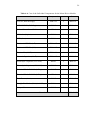
6.1
Project Gantt Chart (Semester One)
56
6.2
Project Gantt Chart (Semester Two)
57
6.3
Cost Estimation for the Mechanical Parts
58
6.4
Cost of the Individual Components for the Motor Driver
59
36-37
Module
6.5
Cost Estimation for the Electronics Components
60
6.6
Total Cost for the Whole Project
60
xii
LIST OF FIGURES
FIGURE NO.
TITLE
PAGE
2.1
GPS Segments
7
2.2
Space Segment
8
2.3
Intersection of Three Satellites
9
2.4
Multipath and Atmospheric Interference
10
2.5
List of Types of GPS Sentences
12
2.6
Route
13
2.7
Mobile Hexapedal Robot
14
2.8
The Path for the Hexapedal Robot on Google Earth
15
2.9
Hwan-Seok's Autonomous Mobile Robot Using GPS
16
2.10
Hamid's Mobile Robot Structure
17
2.11
Flowchart for Hamid's Mobile Robot
18
2.12
The Structure of Pioneer 3DX Mobile Robot
19
3.1
The Sections of the Chapter 3
21
3.2
The Flowchart for the Whole Project
23
3.3
The Control Block Diagram
24
xiii
3.4
Isometric View of the Robot
26
3.5
Side View of the Robot
26
3.6
Top View of the Robot
27
3.7
Front View of the Robot
27
3.8
Tamiya 9801112M Mabuchi FA-130
28
3.9
Dimensions of Tamiya 9801112M Mabuchi FA-130
29
3.10
Tamiya 70097 Twin-Motor Gearbox Kit
30
3.11
The Main Electronics Components
31
3.12
Arduino Uno R3 Board
32
3.13
Arduino UNO Pinout Reference
33
3.14
Arduino Software Interface
34
3.15
Adafruit Ultimate GPS Logger Shield
35
3.16
GPS Shield Placed on Arduino UNO
35
3.17
Raw NMEA Sentences
36
3.18
L293D Motor Driver IC
39
3.19
L293D Connection Diagram
39
3.20
74HC595 Shift Register
40
3.21
Motor Driver Shield
40
3.22
Flowchart
42
xiv
4.1
Top View of the Actual Autonomous Mobile Robot
46
4.2
Side View of the Actual Autonomous Mobile Robot
46
4.3
Movement of the Mobile Robot
47
4.4
Open Basketball Court
47
4.5
Reading from GPS in the Serial Monitor
48
4.6
Path of the Mobile Robot
49
4.7
Mobile Robot in Action at Stating Point
49
4.8
Mobile Robot in Action at First Point
50
4.9
Mobile Robot in Action at Target
50
xv
LIST OF ABBREVIATION
GPS
-
Global Positioning System
IR
-
Infrared Sensor
RFID
-
Radio Frequency Identification
DC
-
Direct Current
PPS
-
Precise Positioning Service
SPS
-
Standard Positioning Service
SA
-
Selective Availability
DGPS
-
Real-Time Differential GPS
NMEA
-
National Marine Electronics Association
INS
-
Inertial Navigation System
GPRS
-
General Packet Radio Service
PC
-
Personal Computer
USB
-
Universal Serial Bus
AC
-
Alternating Current
LIPO
-
Lithium Polymer
GMT
-
Greenwich Mean Time
GPRMC
-
Global Positioning Recommended Minimum Coordinates
ASCII
-
American Standard Code for Information Interchange
xvi
mAH
-
milli Ampere-Hour
Tt
-
Travel Time,
Trt
-
Signal Reception Time
Ttt
-
Signal Transmission Time
D
-
Distance
c
Speed of Light
PCB
-
Printed Circuit Board
FTDI
-
Future Technology Devices International
I/O
-
Input/Output
SRAM
-
Static Random Access Memory
EEPROM
-
Electrically Erasable Programmable Read Only Memory
LDR
-
Light-Dependent Resistor
RTK
-
Real-Time Kinematic
LED
-
Light-Emitting Diode
xc
-
Longitude of the Current Location
xn
-
Longitude of the Next Location
yc
-
Latitude of the Current Location
yn
-
Latitude of the Next Location
KTC
-
Kolej Tuanku Canselor in UTM
Li-Ion
-
Lithium Ion Battery
xvii
LIST OF APPENDICES
APPENDIX
TITLE
PAGE
A
Motor Driver Shield Schematics
63
B
The Code to Read the Data from GPS
64
C
The Code to Finding the Distance and Angle
68
D
The Code of the Whole Project
71
1
CHAPTER 1
INTRODUCTION
1.1
Introduction
This chapter discusses about the project background, the objective, the scope,
the problem statement and the organization of thesis. The background provides the
important information for the project. The objective shows the expected result while
the scope of the project mentions the limitations, boundaries and specifications of the
project. The problem statement of the project describes the issue of the conducting
the project. Finally the organization of thesis gives the basic ides of every chapter in
this thesis.
1.2
Background of the Project
The need of using robots in industries and companies has increased recently.
A robot is an intelligent agent that performs tasks with or without help. Robots
appear in different types in daily life depending on their tasks and they are used for
2
many purposes starting from simple purpose such as household purpose to military
and space purposes. However, the more advance the robot becomes, the less needs
for human control on robots [1].
Autonomous mobile robot is an automatic machine that can move around in
its environment and it is not fixed to one position. This is the reason why mobile
robots have been widely used for agricultural, industrial and military purposes. They
can be used in different locations such as schools, hospitals, homes, military camps
and others. The feature of autonomous makes the robot independent. Therefore, they
do not need the human’s help to move from one place to another. One of the top
advantages of autonomous mobile robots is that they can save time and lives and
lower the possibility of injuries among humans [2].
Navigation mobile robot is a mobile robot which can find its way from its
current (or pre-defined) location into a desired (pre-programmed) location by
monitoring and controlling its movements without the need of the user's help.
Therefore, the main two tasks given to the mobile robot are to move around in its
environment and to determine whether or not the final destination has been reached.
In order to do that, the mobile robot should know its physical position and
environment using its knowledge and the sensors information from its environment
[3]. These sensors give the robot the ability to know its path and gather information
[1]. Different sensors have different ranges and different functions. There are short
range sensors such as IR sensors and there are long range ones such as global
positioning system (GPS) [2]. Furthermore, several methods are used for path
planning such as GPS, radar, Radio Frequency Identification (RFID), line following
navigation and etc. For outdoors navigation, GPS is considered as the most ideal
navigation system regardless of weather conditions and day time [4].
After the military coding has been removed, the need of using GPS has
increased as it can be used for several applications such as communication,
construction, intelligent vehicles and airplanes. Using GPS in outdoor localization in
large environment became a popular solution since GPS has an amazing property in
collecting information without adding special device such as sensors and reflectors
3
[5]. In addition, robots can locate positions in 2D coordinate system (latitude and
longitude) or 3D coordinate system (latitude, longitude and altitude). This ability is
very useful in avoiding complicated control of coordinate systems. In outdoor
navigation, the position of the robot is determined by a combination of GPS and
odometry which use the data from the motions to compute the distance. This is done
by collecting information of the movement from the robot’s wheels and counting the
rotation [3]. This way is the same as how blindfolded people approximate their
position by counting their steps. By integrating a GPS into a robot, the robot will be
able to determine its own position and move in a path toward its goal. However, GPS
is not suitable for indoor navigation because the walls will block the satellite signals.
1.3
Objectives
The objectives of this project are:
i)
To get the current location coordinates of the mobile robot from the
satellites.
ii)
To design an autonomous mobile robot that can navigate itself from
its own position to a specific position using GPS.
1.4
Project Scope
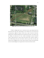
Full strength of the satellites signals is needed for the GPS to provide an
accurate coordinates. Due to the fact that satellites signals cannot penetrate walls,
buildings and trees, the mobile robot should move in an open area such as an open
basketball court. Another advantage of this place is that it is a plane surface and does
not have many obstacles.
4
The robot used in this project will be a four-wheeled mobile robot with the
following limitations and specifications:
i) It is an outdoor autonomous mobile robot, so it cannot move inside
buildings since the satellites signals cannot penetrate the walls.
ii) Mobile robot should always head west when starting.
iii) The robot is not programmed to avoid obstacles
1.5
Problem Statement
Many researches gave ideas and methods for navigating a mobile robot from
one position to another. They used different types of control and systems. As the
complexity the robot increases, the cost will increase, as well. The mobile robot will
be focusing on outdoors navigation. Therefore, some navigation methods are not
suitable for outdoors navigation. Radar and Radio Frequency Identification (RFID)
can be used but they have some problems since radar requires a large size processor
and will be expensive while RFID does not seem practical because it only covers
short distance. In outdoor navigation, a long range method is a need to cover the
whole area. One of these methods is global positioning system (GPS) which is
suitable due to it long range, simplicity and cheap price.
1.6
Organization of Thesis
This report basically consists of 6 chapters. Chapter 1 gives a general idea of
the project proposed. It is divided into 4 parts; background of the project, objectives,
scope and problem statement. Chapter 2 presents more information on GPS and
literature review of some previous similar projects, and. It explains more details on
5
GPS, NMEA Protocol and waypoint. Chapter 3 is about the methodology of in the
project. The system overall, mechanical structure, the components, the techniques
and the process done in this project are all mentioned in details. Chapter 4 shows the
results and outcomes of this project followed by the discussion based on the results
of the project. Chapter 5 covers the conclusion for the project in general and some
recommendations are provided for future development. Chapter 6 is about the project
management which contains the project schedule, the estimated cost of the individual
components and total cost of the whole project.
6
CHAPTER 2
LITERATURE REVIEW
2.1
Introduction
A literature review of previous similar projects was conducted prior to the
start of this project. This chapter provides a plenty of information about GPS and
gives some ideas on previous projects and attempts done by researches toward using
GPS as a navigation method
2.2
Global Positioning System (GPS)
The NAVSTAR global positioning system (GPS) is a satellite radio
navigation system that is used to determine any position and provide time
information, irrespective of the weather, anywhere on earth. There are two services
provided by GPS: Precise Positioning Service (PPS) and Standard Positioning
Service (SPS). The PPS is very accurate in determining the position and time but
only available for authorized users such as military. On the other hand, SPS is
7
available for all users but less accurate. Selective availability (SA) is a feature used
in SPS to reduce the accuracy of the GPS [6].
Originally, GPS was invented for military purposes by the by the Defense
Department of US, but, during the 1980s, the US government made this technology
open for all civilian purpose but with a limitation in position accuracy. Until May
2000, the Defense Department of US has removed the degradation integrated on
civilian GPS. So, the selective availability (SA) is not used recently, however, it can
be reactivated without
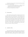
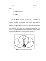
witho noticing the users [7]. GPS consists of three important
importa
segments [8] as shown in figure 2.1 and these are as followed:
Figure 2.1: GPS Segments
i.
Space (satellite) segment
As shown in figure 2.2,
2.2, the space segment consists of 24 satellites
which orbit around the earth twice a day (one complete cycle every 12
hours). There are 6 different orbital planes with 4 satellites on each orbital
and each satellite has a number of atomic clocks to maintain the time
accuracy.
8
Figure 2.2: Space Segment
ii.
Control segment
It consists of the control and monitor stations. There are five control stations
around the world: four unmanned monitoring stations and one master
control station. They monitor the satellites by tracking them and the master
one corrects the time and orbital information if any error occurred such as
satellites and atomic errors and orbit errors.
iii.
User segment
It consist of the user whether they were civilian or militant and their
GPS receiver. The number of GPS holders can be limitless.
In order to determine any position in 3D, at least four satellites are needed to
be seen be the GPS receiver. Three satellites are used to locate the position and one
to correct the time on the receiver. This is done by sending a signal to the first
satellite that contains the satellite's location and the signal's time of departure. The
receiver, then, multiplies the signal's travel time by the speed of light to calculate the
distance between the satellite and the receiver [9]. These are the equations that are
used in the process:
9
Tt =Trt - Ttt
(Eq. 2.1)
D = tt x c
(Eq. 2.2)
Where:
Tt is Travel time,
time
Trt is signal reception time
Ttt is signal transmission time
D is Distance
c is the speed of light
With one satellite, the receiver will know that it is located at the
circumference of a sphere where the satellite is its center and with a radius equals to
the distance. Same thing happens with the second and third satellite. With two
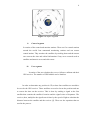
satellites, the area will be narrowed to a circumference of a circle. But with three
satellites, the area will be reduced to just one point [9] which is the similar to what is
shown in figure 2.3.
2.3 However, the more satellite the receiver sees, the better
accuracy it provides. GPS is not just used to determine any position on earth, it can
be used to do a plenty of application such as navigating from one location to another,
creating maps, and determining the distance between two locations [7].
Figure 2.3: Intersection of Three Satellites
10
However, GPS is not a perfect system. It has some errors and limitation that
may cause wrong reading. These errors are caused by the user or the surrounding
environment such as [7]:
i.
Multipath inference:
This error occurs due to the reflection of the signal from other
objects in the environment such as trees, buildings, vehicles, and other
ot
objects as shown in figure 2.4. These signals are hard to avoid, so the
receiver receive them. However, this error can be solve be using Real-Time
Real
Differential GPS (DGPS) which will be discussed lately.
Figure 2.4: Multipath and Atmospheric Interference
ii.
Atmospheric interference
This interference usually affects the signal by causing it to become
slower or faster. This error can also be solved by using an advanced RealReal
Time Differential GPS (DGPS).
iii.
Receiver clock error
Since the receiver cannot have an atomic clock which is very
accurate and integrated in the satellites. Therefore, a slight positioning error
11
can occur in the receiver. However, as mentioned early, this error is
corrected by the monitor and control stations.
iv.
Orbital error
Sometimes the satellite deviates from its normal path which will
cause a small error in the received position. However, this error is also
corrected by the monitor and control stations.
v.
User mistakes
There are different types of user mistakes such as entering incorrect
information or blocking the signal since the human's body can block signals.
These errors cannot be solved especially entering incorrect information.
Therefore, the user should be careful when using GPS receiver.
Real-Time Differential GPS (DGPS) is designed to reduce GPS errors. It
employs another stationary GPS receiver to minimize the errors caused by the
multipath inference, orbital errors and other errors. This is done by placing a GPS
receiver known as a reference station at a known location. By comparing between
the received signal and the actual signal from the reference station, the difference
between them is known as the differential correction. By applying this differential
correction into the receiver, the errors will be removed and the accuracy will be
improved [8]. The best thing about GPS is that it can function under any weather for
24 hours a day with no fees and charges as long as it is placed in an open place.
12
2.3
NMEA Protocol
Protocol is set to allow the GPS receiver to connect and transmit data with
the satellite. One of these protocols is National Marine Electronics Association
(NMEA) which is the most common protocol.
protocol. NMEA defines the interface between
the different pieces of marine tools including GPS receiver. It is an ASCII-based
ASCII
protocol to transmit data and the transmitted line of data is called sentence which is
independent from other sentences. Each sentence
sentence start with a dollar sign ($),
followed by two letter known as the talker ID which is the prefix for GPS (GP) [10].
Then, it is followed by a three letter known as the message ID which is the type
(content) of the sentence such as GGA, GSA, VTG, DTM and other
ther shown in figure
2.5.. After this, the sentence continues with the body which contain of various data.
The data contains of information about the date, time, position (latitude, longitude
and attitude), speed and other information [11].
Figure 2.5: List of Types of GPS Sentences
13
2.4
Waypoints
A waypoint, sometime called landmark, is a location based on the geographic
coordinate (latitude/longitude) stored in the memory of the receiver. Once it is saved
in the memory, it only can be edited or deleted by the user.. It is created by either
saving the location or manually entering the coordinates in the receiver [7]. A
sequence of waypoint is known as a route as shown in figure 2.6.. During navigation,
the robot or GPS receiver will move through the path which is a sequence of
waypoint. When reaching a waypoint, the GPS receiver will automatically navigate
to the next waypoint in the list. The process is doing in every waypoint until the
robot reaches the desired location.
Figure 2.6: Route
2.5
Pervious projects
This section discusses
discuss some of the related works and projects done by other
researcher toward GPS as navigation method.
14
2.5.1
A Mobile Hexapedal Robot
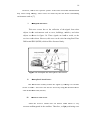
Dupree [1] from University of Pennsylvania made an autonomization of a
RHex mobile robot using a GPS in the GRASP lab of the university
niversity where figure 2.7
shows a picture of the robot. RHex is a six-legged
six legged highly mobile robot which is more
stable than three or four legged robots and has a great flexibility in its movement. By
integrating
ating a GPS module into the robot, the robot was given the ability to know its
location and navigate itself to any pre-programmed
pre programmed point by following a breadcrumb
path of way-points.
points. A Python code, which is a general-purpose
purpose and high-level
programming language
age,, is used to control the robot .It was assumed that no obstacles
will appear in the robot's path.
pat The path is shown in figure 2.8.
Figure 2.7: Mobile Hexapedal Robot
15
Figure 2.8: The Path for the Hexapedal Robot on Google Earth
Finally, by using Python code to control the robot,
robot a great improvement was
showed but there were some disadvantages of this method. First, the robot turn left
or right quickly, whether the angle is small or big. A gain is needed to control the
turning speed
ed so that the turning speed will depend on the angle. If the angle is big,
the turning will be fast, and vice versa. Another disadvantage is that the controller
could be improved to get a better result and would be more efficient. Despite of
these disadvantages,
ntages, the project succeeded to match its goal which was using GPS
module, basic trigonometry and a linear control system to navigate a hexapodal robot
from its location through some waypoint until it reaches the desired location.
16
2.5.2
Autonomous Mobile
M
Robot Using GPS
In 2005, Hwan-Seok
Hwan
et al. [4] designed a robot, as shown in figure 2.9. This
robot is comprised of a GPS receiver, RF communication device and a photo-sensor.
photo
The GPS receiver was used to determine the location and moves the robot toward the
correct position. The movement was monitored by a wireless RF communication
module, while the photo
oto sensor is used to avoid obstacles.
Figure 2.9: Hwan-Seok’s
Seok’s Autonomous Mobile Robot Using GPS
The robot was consisted of 4 parts. First part contains the GPS module which
receives the satellites signal and determines the position. They used a GPcorel200
GP
12
channel modules. The output signal from the receiver is RS-232
RS 232 signal which, by the
help of converting circuit, can be converted to TTL signal. Second part is the Central
Processing Unit (CPU) which compares between the locations
locations to determine the
shortest distance. Third part contains a RF communication device which is
comprised of a transmitter and receiver. It is used is to monitor the actual mobile
traces. Last part is the photo-sensor
photo sensor which senses the obstacles in front of the robot.
17
The advantage
antage of this robot is that it is a low-cost
low cost robot with a stable
navigation device. However, there are some parts that need improvement to get
better results such as using different avoidance system because photo-sensors
photo
cannot
avoid small obstacles or those
those in black color. Another way to improve the project is
to use a hybrid system such as GPS/INS system to minimize the GPS error.
2.5.3
Avoiding Obstacles Using Commanded Loop Daisy Chaining
Chain
Method
Hamid et al. (2009) [2] did a research on combining GPS with sonar sensors
for a mobile
le robot, shown is figure 2.10.
2.10 The GPS determines the location,
location while the
LV-MAX
MAX sonar sensor is the system used to avoid obstacles during the navigation
process. The sensors cause some crosstalk between them and this crosstalk will
create invalid data. To overcome this, the triggering the sensor one at time by using
commanded loop daisy chaining application method. The robot will navigate itself
and avoid obstacles
acles at the same time. Figure 2.11 show the flowchart for the system.
The main problem in this project was the avoidance sensor, so it was advised to a
better obstacle avoidance system with a higher accuracy.
Figure 2.10: Hamid’s Mobile Robot Structure
18
Figure 2.10: Hamid’s Mobile Robot Structure
Figure 2.11: Flowchart for Hamid’s Mobile Robot
2.5.4
Pioneer 3DX Mobile Platform Using
U
GPS/GPRS Commu
ommunication
In 2011, Velagic et al. [12] made a paper about a navigation system using a
combination of GPS and GPRS communication where the GPS connected the robot
with the satellites and the GPRS connected the robot with a server. The server was a
Personal Computer (PC) connected to the
the internet as shown in figure 2.12. To avoid
19
obstacles, a multiple algorithms, including Fuzzy control, were proposed to ensure
the safety of the path.
Figure 2.12: The Structure of Pioneer 3DX Mobile Robot
Pioneer 3DX mobile platform was used connected with the PC by a RS232
communication standard and the GPS/GPRS module was built using Cinterion XT65
platform. The connection between the PC and the robot is bi-directional
bi directional connection.
The robot sends the information it got by the GPS communication to the PC and the
PC analysis the data and gives command to the robot, whether to start moving, to
stop moving or to turn. The portable PC is also used in avoiding obstacles. There are
ar
three ways to avoid obstacles. The first one is manual
al control from the PC keyboard.
The second way is avoiding
avoid
front algorithm for simple obstacles, and the last way is
using fuzzy control based algorithm for difficult obstacles. In this project, they used
MATLAB to program and communicate with the robot.
20
2.6
Summary of the Chapter
The chapter gave more knowledge about GPS, NMEA protocol and
waypoints. It also discussed about methods and projects that has been done
previously on the same topic. From the literature review, it can be noted that some
features and methods can be used in this project. The ability to follow a path of
several waypoints and using Arduino Uno R3 will be used to control the robot in this
project.
21
CHAPTER 3
METHODOLOGY
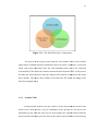
3.1
Introduction
This chapter discusses the methods, tools and components used to design an
autonomous mobile
bile robot. As shown in figure 3.1, this chapter consists of 4 sections:
the project overview, mechanical design,
design electronic circuit design and programming.
The project overview gives a short description of the process that has been used in
this project. Itt is divided into two parts: flowchart and project problem solution.
After that, a detailed explanation is given in the mechanical design. The mechanical
design is also divided into two parts: rigid body and the gearbox. On the other hand,
the electronic circuit
ircuit design provides information about the components used in
fulfill the project. Finally, a suitable programming language is used to control the
microcontroller (Arduino) which is considered to be the brain of the robot.
Project
Overview
Mechanical
Design
Electronic
Circuitry
Design
Programming
Figure 3.1: The Sections of the Chapter 3
22
3.2
Project Overview
This section is a short description of the main ideas needed to complete the
project. This section divided into two parts where the first part is about the steps
needed to be done and the second one is the idea of the problem solution used in the
project to achieve the objectives.
3.2.1
The Main Steps
This project is divided into two parts: hardware and software design. The
flowchart in figure 3.2 shows the process for the whole project. The process started
by searching and finding a solution for the problem statement. That was done by
reading and being well acquainted with previous projects and studies related to the
same problem statement. This has been explained briefly in chapter 2. Using the
information and knowledge gained from the literature review, the mechanical
structure is determined as well as the electronic circuit design. This includes the
components used and the connections between the input which is GPS signal
obtained from the GPS module and the output which is the movement of the mobile
robot. Finally, the last stage was the programming and testing which is the most
important part. This part required a lot of testing and calibration until the robot was
able to function as desired.
23
Figure 3.2: The Flowchart for the Whole Project
24
3.2.2
Project Problem Solution
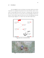
First, the entire path is divided into several waypoints with a different
distance between them.
them Figure 2.6 showed a simple illustration on the idea of the
solution. These waypoints are assigned before the mobile robot starts moving and
saved in the memory of the Arduino. After thee GPS receives the current location
from the satellite, the received location is compared with the location of the first
waypoint. If they are the same, the Arduino skips to the next waypoint in the list
automatically.. If not, the Arduino collects the distance between the locations and the
angle. Based on the distance and the angle, it gives command to the robot to move
toward the waypoint. When reaching the waypoint, the Arduino refresh its location
and compare the new current location with the next
next waypoint. This process will be
repeated until the robot reaches the final desired location. Figure 3.3 shows the
simple block diagram where the controller is Arduino Uno and the mobile robot is
the plant while GPS module provides feedbacks to correct the
the position of the robot.
Figure 3.3: The Control Block Diagram
25
3.3
Mechanical Design
For the mechanical design, the work done to build the mobile robot passed
through 3 stages: manual sketching, sketching using SolidWorks 2013 and the
hardware design of the mobile robot. The component used in the project should be
considered during the mechanical design in order to avoid any problem that may
appear later such as slow movement due to the weight of the robot.
3.3.1
Body Structure
The robot is a two-layer robot. Each layer is made from an acrylic sheet with
the dimension of 170mm x 70mm x 5mm. Acrylic sheet was used because it is easy
to cut and drill it. The mechanical design was done using the SolidWorks 2013
software as shown in figures 3.4 until figure 3.7. Below the base layer, two
gearboxes were placed at the front and back of the robot. Each gearbox has two DC
motor which are controlled separately. In the middle layer, two different types of
batteries were placed; 7.4V 900mAH LIPO battery placed at the front of the
structure and 6x AA Energizer battery place at the back. On the top of the second
layer, the electronic circuitry (including the microcontroller and GPS module) was
placed.
Overall, the robot structure consists of the following:
i) Two layer of robot.
ii) Two Tamiya gear boxes, each gearbox has 2 x Tamiya motor.
iii) 4 x Tamiya tires.
iv) PCB Stands
26
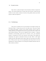
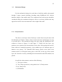
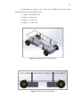
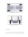
As mentioned, the figures below show the SolidWorks drawing of the
mechanical design in four different views:
i) Figure 3.4: Isometric view
ii) Figure 3.5: Side view
iii) Figure 3.6: Top view
iv) Figure 3.7: Front view
Figure 3.4: Isometric View of the Robot
Figure 3.5: Side View of the Robot
27
Figure 3.6: Top View of the Robot
Figure 3.7: Front View of the Robot
3.3.2
DC Motors
There are different types of DC motors such as Brushed DC motors,
Brushless DC motors, servo motors, ball bearing motors, permanent magnet stators
28
and others. DC motor converts the direct voltage or current into a movement usually
a rotational movement. DC can be connected directly to a power source such as
battery and any other power supply. It needs only two wires to control the direction
of its movement.
DC motors are bi-directional motor; they can move either forward or
backward. This is done by reversing the polarity of the supply or source. Usually,
DC motor required a voltage between 6V and 12V and a current rating between
1Amp and 3Amp [13]. The speed of the motor is controlled by varying the voltage,
more voltage will produce more speed.
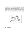
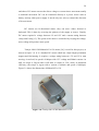
Tamiya 9801112M Mabuchi FA-130 motor [14] is used for this project, as
shown in figure 3.8. It is a brushed DC motor which has a high output permanent
magnet and flat housing. It requires a voltage rating between 1.5V and 3V to start
moving. At no load, its speed is 9100rpm with 1.5V voltage and 200mA current. At
stall, its torque is 26g.cm and it will draw a current of 2.2A, while, at maximum
efficiency, the torque is 6g.cm with a current of 660mA and speed of 6990rpm.
Figure 3.9 shows the dimensions of Mabuchi FA-130.
Figure 3.8: Tamiya 9801112M Mabuchi FA-130
29
Figure 3.9: Dimensions of Tamiya 9801112M Mabuchi FA-130
FA
3.3.3
Tamiya Twin
win-Motor Gearbox
DC motors cannot be connected directly to the wheels because of the
difference in motors shaft and the holes of the wheel. Therefore, a special design is
needed to connect between the wheel and the DC motor’s shaft. The Tamiya 70097
twin motor gearbox kit
k was used for moving the motor. It is consists of two Tamiya
9801112M Mabuchi FA-130
FA
motors and a gearing system.
The plastic gearbox also provides a casing for the DC motors as shown in
figure 3.10. The gearbox has 3 types of configuration; type A, B, and C. The
configuration of the gears determines its speed and torque. Different types of
configuration lead to different speed and torque. Type A and B have a low torque but
high speed with a gear ratio
ratio of 58:1. On the other hand, Type C has higher torque but
less speed with a gear ratio of 203:1 [15]. Type C is selected in this project since it
provides more torque and allows the two wheels to move separately.
30
Figure 3.10: Tamiya 70097 Twin-Motor Gearbox Kit
3.4
Electronic Circuit Design
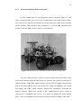
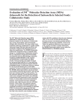
In this section, the electronic components of the mobile robot are described.
It is about how the different components used in the project were connected to be
able to achieve the objectives. The main components used are GPS module, Arduino
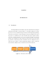
UNO and motor driver module as shown in figure 3.11. The fact that the components
cannot perform the task individually, so these components require a good
understanding on their specifications and the capability of the Arduino UNO
(microcontroller) must be considered at every step to achieve the objectives.
31
Figure 3.11:
3.1 The Main Electronics Components
The process of the project starts when the GPS module receives the satellite
signal which contains different information such as location coordinates, Greenwich
Mean Time (GMT) and other data. The GPS transmitter and receiver are connected
with Arduino UNO. After the Arduino obtains the data from the GPS, it will process
the data and, based on these data, the Arduino will send the command to the motor
drive module. The motor drive module will control
control the DC motor according to the
direction assigned into
to it.
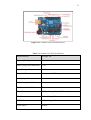
3.4.1
Arduino UNO
In this project, Arduino Uno R3 is used to be the microcontroller which is the
brain for the whole project. It gives commands to the operator. It will receive the
information
on given from the GPS receiver and compare the current location with the
desired location and then gives the order to the mobile robot whether to start moving,
32
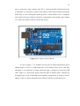
stop or turn left or right. Arduino Uno R3 is a microcontroller board based on the
ATmega328. It is the latest version of the Arduino UNO board. Instead of using the
FTDI chip, it uses ATmega8U2 which provides a faster transfer rate. It integrates
and connects between different electronic components in the mobile robot. Figure
3.12 shows the Arduino Uno R3 used in this project.
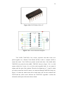
Figure 3.12: Arduino Uno R3 Board
As seen in figure 3.12, Arduino Uno R3 has 14 digital input/output and 6
analog inputs as well as a USB connection, a reset button, and a power jack. One
advantage is its simplicity of being connected with a computer by using its USB
cable. Figure 3.13 show better picture about the pins in Arduino UNO. Arduino can
be supplied by 3 ways; connecting to the computer, using battery or using AC-to-DC
adapter. Table 3.1 shows summary about Arduino UNO R3 specifications [16].
33
Figure 3.13: Arduino UNO Pinout Reference
Table 3.1: Arduino Uno R3 Specifications
Microcontroller
ATmega 328
Operating Voltage
5V
Input Voltage (Recommended)
7-12V
Input Voltage (Limits)
6-20V
Digital I/O Pins
14 (6 provides PWM output)
Analog Input Pins
6
DC Current per I/O Pins
40mA
DC Current for 3.3V Pin
50mA
Flash Memory
32KB (ATmega 328) ; O.5KB used by bootloader
SRAM
2KB (ATmega 328)
EEPROM
1KB (ATmega 328)
Clock Speed
16MHz
34
Arduino, in general, is widely used as a microcontroller because it is an open
source and can be programmed easily. Besides that, it includes the needed device to
support the microcontroller. It also contains many and different types of open source
libraries in the internet which could be used to help
help the researcher and Arduino
users. The Arduino Uno is programmed by using specific software called Arduino
software,
e, shown in figure 3.14.
3.1 Programming can be done easily using this software
because it is using a standard programming language and there are many sample
programs in its library since it is an open source.
Figure 3.14:
3.1 Arduino Software Interface
35
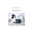
3.4.2
GPS Module
Adafruit ultimate
ltimate GPS logger shield,, shown in figure 3.15,
3.1 was used as the
GPS module for this project. It has a good accuracy with a position accuracy of 1.8m
and a high sensitivity receiver (-165 dB tracking). It also has a built-in
built antenna and
can track up to 22 satellites on 66 channels. Its power usage is incredibly low since it
can be powered it with
wit 3.3-5VDC and it only needs 20mA
mA during navigation. This
GPS shield functions greatly fit with Arduino UNO and is designed to able to save
data into an SD card, if needed [17]. Figure 3.16 show the how the shield can fit on
Arduino UNO. However, the GPS module should be placed on the top to avoid
blocking the satellites signal.
s
Figure 3.15:
3.1 Adafruit Ultimate GPS Logger Shield
Figure 3.16:
3.1 GPS Shield Placed on Arduino UNO
36
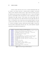
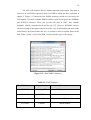
The GPS will transmit data to Arduino through serial output. This data is
shown in an ASCII-based protocol known as NMEA, which has been explained in
chapter 2. Figure 3.17 shows the raw NMEA sentences which are received by the
GPS module. The most common NMEA sentences used in navigation are $GPRMC
and $GPGGA sentences. These two provides the time in GMT, date, latitude,
longitude, altitude, estimated speed and fix type [17]. However, $GPRMC sentence
can be used only in navigation since it provides a lot of information and most of the
useful data in provided within this line. A comma is used to separate between the
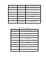
data. Table 3.2 and 3.3 shows the RMC sentence and the types of fix quality.
Figure 3.17: Raw NMEA Sentences
Table 3.2: RMC Sentence
The RMC Sentence
Type of data
Description
$GPRMC
Message ID
RMC protocol header
172914.000
GMT
hhmmss.sss
A
Status Code
A for active and V for void (invalid)
0133.2402
Latitude
ddmm.mmmm
37
The RMC Sentence
Type of data
Description
N
N/S Indicator
N for North and S for South
10338.9001
Longitude
dddmm.mmmm
E
E/W Indicator
E for east and W for West
0.09
Ground Speed
knots
0.00
Tracking Angle
Degree
140414
Date
ddmmyy
*61
Checksum data
XX data starts with *
Table 3.3: Types of Fix Quality
Value
Types
0
Invalid
1
GPS Fix (SPS)
2
DGPS Fix
3
PPS Fix
4
Real Time Kinematic
5
Float RTK
6
estimated dead reckoning
7
Manual input mode
8
Simulation mode
38
Three types of data are used in this project; status code, latitude and
longitude. Status code will indicate if the data receive is valid or not; ‘A’ represent
for active while ‘V’ represents for void. When the ‘V’ appears a LED light will keep
blinking until the data in valid and the status is active. Latitude and longitude or the
necessary coordinates needed to determine positions on earth surface. Latitude
ranges from 0 to 90 degrees while longitude ranges from 0 to 180 degrees.
3.4.3
Motor Driver Module
DC motor cannot be directly connected to Arduino because they draw a high
current. One DC motor needs around 660mA while Arduino only provides 40mA for
each I/O pin. Therefore, Arduino board will face huge damage and will break down
if a direct connection is made. Usually, a motor driver is used to connect Arduino or
any microcontrollers with DC motors. Motor drive receives the signal and orders
from the Arduino and controls the motor based on those orders. It has an external
power supply which should be suitable and enough to drive the motors.
There are different medium that can be used as interface between motor and
microcontrollers, in general, such as relays, power MOSFET, transistors and HBridge drivers, L293D and others. L293D, shown in figure 3.18, was chosen because
it easy to use, easy to be programmed and each chip can control two motors. L293D
is a quadruple half-H bridge driver which has 16 pins and provides bi-directional
directional for both motor [13]. The suffix “D” means that flyback diodes are built in
to minimize inductive. The chip has two inputs and two output to control one motor.
The inputs are connected to the Arduino while the outputs are connected to DC
motor. However, two L293Ds were used since the mobile robot is a four wheeled
robot. Figure 3.19 shows the connection between L293D and motors.
39
Figure 3.18: L293D Motor Driver IC
Figure 3.19: L293D Connection Diagram
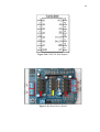
Two L293D, 74HC595N, Led, resistor, capacitors and other items were
placed together on a Printed Circuit Board (PCB) to make a complete shield to
control the motor. Two L293D were placed on the both sides of the shield while
74HC595N was placed in the middle. 74HC595, shown in figure 3.20, is a shift
register which has 16 pins. It is an 8-bit serial-to-parallel latch. It can control 8
outputs with few pins of the Arduino. Therefore, the digital pin 4, 7, 8 and 12 which
are used to control the four DC motors, are connected through 74HC595N chip [18].
Figure 3.21 show the whole motor driver shield where the red arrow indicates the
L293D and the yellow arrow indicates the 74HC595N. Appendix A shows the
schematics and layout of the motor driver shield.
40
Figure 3.20: 74HC595 Shift Register
Figure 3.21: Motor Driver Shield
41
3.5
Software Design
Software design is the most important and critical part of the project. In this
section, the components are programmed and tested until they function as desired.
Arduino will be programmed using its own program interface to read the data from
GPS and send order (movement) to the motor driver. Before proceeding with the
code, the flowchart should be designed first. This helps in having a better and clear
view of the flow of the programming and also keeps tracking the robot’s behavior.
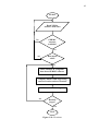
Figure 3.22 illustrates the flowchart of the mobile robot.
In figure 3.22, the programming starts by reading from the GPS. If the data is
available, it will get the coordinates of the current location. Comparison between the
current location and next location is done by computing the distance and angle. By
knowing these two variables, the robot will move to the next location. Then, the
same concept is repeated until it reaches the end.
Appendix B shows the sample code used to get the data – the needed data
including the coordinates of the location- from the GPRMC sentence. However, the
latitude and longitude should be converted from ACSII form to another form known
as decimal form. This is done by extracting the degree value and dividing the rest by
60. After that the degree value is summed with the result of the division to get the
decimal form.
42
START
Read NEMA
sentence from GPS
GPRMC
sentence
available?
No
Yes
No
Data status
valid?
Yes
Read Latitude & Longitude
data from GPRMC sentence
Compute distance and angle using
current location and next location
Move toward the target
No
Reached
target?
Yes
End
Figure 3.22: Flowchart
43
Appendix C shows the sample code used for finding the distance and angle
between two locations. The Haversine formula was used to find the distance or
shortest path between two points [19]. To find the angle, a different method is used
where the heading is found and then the previous heading (in decimal) is subtracted
from the current heading (in decimal) to form the angle. At the starting point, the
previous heading is set to be 270 since the mobile robot should head to the west
when starting. Firstly, the difference between the latitude and longitude is calculated
in term of radians:
dx = radians [xn – xc]
(Eq. 3.1)
dy = radians [yn – yc]
(Eq. 3.2)
Where:
xc is longitude of the current location and xn is longitude of the next location
yc is latitude of the current location and yn is latitude of the next location
After that, the latitude and longitude of the two locations are converted into
radians and the following formulas - known as Haversine formula in [19] – are used:
Distance = sin2(dy/2) + cos (yc) * cos(yn) * sin2(dx/2)
(Eq. 3.3)
Heading = atan 2*[sin dx *cos yn, cos yc *sin yn – sin yn *cos yc *cos dx],
2*PI
(Eq. 3.4)
By knowing the distance and angle, the robot will be able to move in the next
location. This is done by controlling the DC motors and some sample code were
found in the internet [20]. Appendix D shows the whole code for the mobile robot.
44
3.6
Summary of the Chapter
This chapter discusses briefly the mobile robot in terms of its hardware
components and electronic design. It is a two-layer mobile robot which uses four DC
motor for movement. It consists of three modules. Arduino UNO is used as
microcontrollers and connects the whole system together. GPS module will get the
coordinates from the satellites and send it to the microcontroller. Motor driver
module connects between the microcontroller and DC motors. It receives orders
from the microcontroller and control the motor based on the orders. In order to make
the robot moves as desired, all the hardware and software must be carefully selected,
designed, integrated and tested.
45
CHAPTER 4
RESULTS AND DISCUSSION
4.1
Introduction
In this chapter, the results and outcomes of the project are discussed. The
results include the final design, robot movement, reading data from the GPS, final
result and the effectiveness of the robot.
4.2
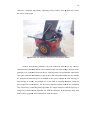
Final Design
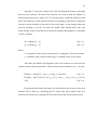
After connect the electronic components together and also integrating the
whole body with Tamiya DC motor, the autonomous mobile robot was built, as
shown in figure 4.1 and figure 4.2. Figure 4.1 shows the top view where the red
arrow indicates the GPS module placed on a PCB and the yellow arrow indicates the
motor driver module. The GPS module is placed on the top, so the satellite signals
will not be block by any equipment. The Arduino UNO is placed directly under the
motor driver module. Two LEDs that are placed on the PSC board will blink when
46
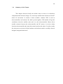
receiving the latitude and longitude. While figure
igure 4.2 shows the side view of the
mobile robot.
Figure 4.1: Top View of the Actual Autonomous Mobile Robot
Figure 4.2: Side View of the Actual Autonomous Mobile Robot
47
4.3
Robot Movement
The autonomous mobile robot has been design to move forward, move
backward and turn right and left with two different speeds.. Figure 4.3 illustrates the
movement of the mobile robot. The two gearbox should make the same move
together so the robot will move, otherwise, the robot will be shaking and may cause
the gear to break because it receive power and orders from the motor drive
d
and
cannot translate it into
to motion. Figure 4.4 shows a sample open basketball court that
is similar to the field used for the project.
Move Forward
Turn Right with
Low Speed
Turn Left with
Low Speed
Move Backward
Turn Right with
High Speed
Turn Left with
High Speed
Figure 4.3: Movement of the Mobile Robot
Figure 4.4: Open Basketball Court
48
4.4
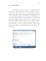
Reading GPS Data
As mentioned earlier, Arduino Uno is able to extract different information
from the GPS. After the GPS module is connected to Arduino, where pin 9 is
connected RX of the GPS module and pin 10 is connected to TX, the code in
appendix B is uploaded to get the needed data provided by GPRMC
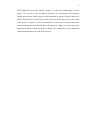
MC sentence. Figure
4.5 shows the output of reading from the GPS module in the Serial Monitor.
Monitor It can
be seen that the time date is the same as shown in the Windows – on the most lowerleft corner.. The latitude and longitude are also shown in two forms. The
Th first form is
the ACSII form which is provided directly from the GPS. The other form is the
decimal form which is converted from ACSII form by equations shown in chapter 3.
3
The location shown is the output is located near KTC-S47
KTC
– outside my room.
Therefore,
fore, the first objective is done completely, where the robot was able to get its
current location.
Figure 4.5: Reading from GPS in the Serial Monitor
49
4.5
Final Result
After calibrating the project and doing several testing, the final code shown
in appendix D was designed and uploaded into the microcontroller (Arduino UNO).
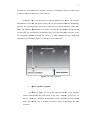
Figure 4.4 showed the field used for the project. A starting point, a final point and
three other points are chosen to be the point for the path planning of mobile robot.
Figure 4.6 shows the basic path of the robot when it moved from starting point to the
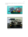
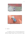
final point (target). Figures 4.7, 4.8 and 4.9 shows the mobile robot in action
Figure 4.6: Path of the Mobile Robot
Figure 4.7: Mobile Robot in Action at Stating Point
50
Figure 4.8: Mobile Robot in Action at First Point
Figure 4.9: Mobile Robot in Action at Target
4.6
Discussion
At the beginning, the location of the final destination and middle points
should be saved before the mobile robot moves. Two LEDs (red LED and green one)
blinks when receiving the coordinates. After that, the robot is put in a random
51
location. By comparing the current location with the next location, the robot will
know the distance and angle. By knowing the distance and angle, the mobile robot is
able to navigate itself from the starting point through the path, crossing the middle
points toward the target location. First, the robot will turn left or right with a degree
according to angle. Then, it will move forward according to the distance. However,
due to the lack of accuracy in the Standard Positioning Service (SPS), the robot may
not be able to cross or reach the exact location. The margin of error is about ± 1.5
meter.
52
CHAPTER 5
CONCLUSION AND RECOMMENDATIONS
5.1
Conclusion
The objectives in this project were successfully fulfilled. First objective is
achieved by using code in appendix B. The robot is able to obtain the coordinates of
its current location from the satellite signals. The second objective is barely achieved
since it required a lot of testing and calibration. However, the position faced an
accuracy error of ±1.5 meter because of the limitation put on the GPS for civilian
users. However, the robot is able to move mostly as desired. Three module were
combined together to build the basic parts of the mobile robot. Though the objectives
were achieved, many challenges were faced during the process. Most of the
challenges were about the batteries and the code. The batteries were changed several
times. The program also was changed several time, as well as the flowchart, but at
the end, the autonomous mobile robot is able to navigate itself from any location to a
desired location. As conclusion, GPS is an advanced sensor that can be used for
several things and it is becoming more and more popular recently.
53
5.2
Recommendations
For future development, many improvements can be done to improve the
functionality and efficiency of the mobile robot. More complex algorithm and
feature can be added and designed such as:
5.2.1
Rechargeable Batteries
Two batteries were used in the project. One of them was a rechargeable LIPO
battery that was used to power the motor driver module, while the other type used to
power the Arduino was a 6x AA Energizer battery which are not rechargeable. This
issue caused many problem and wrong movement. However, it is better to change
the second type into 2x 3.7V 1100mAh Li-Ion Battery which are rechargeable.
5.2.2
Avoidance System
Since the project was not designed to avoid obstacles, no avoidance system
was integrated in the robot. However, in industrial or daily life, different obstacles
will be found on the path. Therefore, a suitable avoidance system must be designed
to be able to know anywhere with any fear that the robot may break or get damaged
due to crashing with the surrounding obstacles. Some of the recommended systems
are using IR sensors or LDR light sensors.
54
5.2.3
Compass
One of the problems was that the robot will not turn exactly according to the
angle. For example, the angle between the two locations is 45 degree, but the robot
will turn with a 40 degree. Therefore, a compass can be used to achieve more
accurate orientation.
55
CHAPTER 6
PROJECT MANAGEMENT
6.1
Introduction
In order to achieve the project objectives within a specified period, an
effective project plan needs to be done. This plan should be organized carefully.
There are many things that restricted the project such as research scope, time, budget
and the availability of the resources. Gantt chart is done to give a clear guideline in
time management and to keep track of the flow of the process.
Cost estimation is performed to make sure that the objectives are fulfilled
with the minimum cost. In this process, market survey was done by searching in the
websites of the electronic supplier to find the suitable components. The components
prices are listed together in few tables to compute the final cost.
56
6.2
Project Schedule
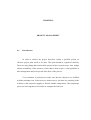
Gantt chart for the first semester is shown in table 6.1. As seen in the table, a
late beginning occurred before deciding a project due to the faculty’s late assign of
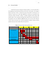
project supervisors. Table 6.2 shows the project Gantt chart for semester two. In
contrast to semester one, some delay happened in semester two especially in the
electronics design and thesis writing. A problem happened when buying GPS
module online, so the component came quite late which caused the whole process to
be postponed. Also, the exhibition (MIRCED 2014) was one week earlier. Because
of these issues, the project was a little bit behind the schedule. Despite all these
problem, the project successfully achieved its objectives.
Table 6.1: Project Gantt Chart (Semester One)
Month
Week
FYP Briefings
Assigned to Supervisor
Deciding a project
Analyzing the topic
Literature Review
Methodology
Seminar Presentation
FYP - report
Sep
Oct
Nov
Dec
1 2 3 4 5 6 7 8 9 10 11 12 13 14 15 16
57
Table 6.2: Project Gantt Chart (Semester Two)
Month
Week
Feb
Mar
Apr
May
June
1 2 3 4 5 6 7 8 9 10 11 12 13 14 15 16 17 18
Literature Review
Hardware Design &
Construction
Assembly Hardware
Electronics Design
Implementation
Programming Design
Test & Troubleshooting
Presentation / Exhibition
Thesis Writing
Thesis Compilation
6.3
Cost Estimation
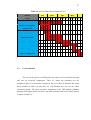
The cost of the project is dividing into two parts; cost for mechanical design
and cost for electrical components. Table 6.3 shows the estimated cost for
mechanical parts. For electronics component, the cost will be in detail for the motor
driver module in table 6.4 and table 6.5 will illustrate the cost for the whole
electronics design. The most expensive component is the GPS module (Adafruit
ultimate GPS logger shield). However, the total estimated cost for the whole project
is shown in table 6.6.
58
Table 6.3: Cost Estimation for the Mechanical Parts
Item
Cost per unit
unit
Price
Acrylic Sheet A4 (5mm)
RM 15
1
RM 15
Tamiya Twin-Motor Gearbox
RM 44
2
RM 88
Tamiya Truck Tire Set
RM 22
2
RM 44
LIPO Battery 7.4V 900mAH
RM 29
1
RM 29
Energizer battery AA size
RM 3
6
RM 18
6xAA Battery Holder (Compact)
RM 3.5
1
RM 3.5
PCB Stand 30mm (screw & screw)
RM 1.4
4
RM 5.6
Screw and nuts (width 3mm)
RM 0.2
10
RM 2
Subtotal
RM 205.1
As seen in table 6.3, the most expensive part in the mechanical design was
the Tamiya gearbox and its pair of tires. They cost a total of RM 132 which is near to
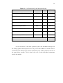
two-thirds of the subtotal cost used for mechanical parts. Table 6.4 shows the cost of
the motor driver module. This is done by the cost of each individual components
used in the module.
59
Table 6.4: Cost of the Individual Components for the Motor Driver Module
Item
Cost per unit
unit
Price
L293D ( Dual H-bridge)
RM 10.8
2
RM 21.6
IC 74HC595N (Shift Register)
RM 1.2
1
RM 1.2
RM 8
1
RM 8
IC Socket (16 pins)
RM 0.4
2
RM 0.8
LED (3mm)
RM 0.1
2
RM 0.2
Resistor 0.35W 5% (1.5k)
RM 0.05
1
RM 0.05
Resistor 0.35W 5% (10k)
RM 0.05
1
RM 0.05
Resistor Bar (100K)
RM 1.00
1
RM 1
Ceramic Capacitor (0.1uF)
RM 0.15
3
RM 0.45
Electrolytic Capacitor (25V/47uF)
RM 0.3
2
RM 0.6
Electrolytic Capacitor (6V/100uF)
RM 0.2
3
RM 0.6
Terminal Block KAR301 (2 Way)
RM 0.7
3
RM 2.1
Terminal Block KAR301 (3 Way)
RM 1
2
RM 2.
Push Button (6mm)
RM 0.5
1
RM 0.5
Straight Pin Header (Male) 1x40 Ways
RM 0.6
1
RM 0.6
Jumper/Shunt
RM 0.3
1
RM 0.3
Printed Circuit Board Fabricated
Subtotal
RM 40.05
60
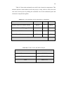
Table 6.5 shows that estimated cost used for the electronics components. This
includes the three main modules used in the project. Lastly, table 6.6 shows the total
cost used for the project by adding the estimated cost of the mechanical parts and
electronics components together.
Table 6.5: Cost Estimation for the Electronics Components
Item
Cost per unit
unit
Price
Arduino Starter Kit Student Edition
RM 80
1
RM 80
Adafruit Ultimate GPS Logger Shield
RM 190
1
RM 190
Motor Driver Module
RM 40.05
1
RM 40.05
Printed Circuit Board
RM 4
1
RM 4
Subtotal
RM 314.05
Table 6.6: Total Cost for the Whole Project
Subtotal
Mechanical Part
RM 205.1
Electronics Components
RM 314.05
Total
RM 519.15
61
REFERENCES
[1]
Dupree, P. (2009). Autonomization of a mobile hexapedal robot using a
GPS.
[2]
Hamid, M. H. A., Adom, A. H., Rahim, N. A., & Rahiman, M. H. F.
(2009). Navigation of mobile robot using Global Positioning System (GPS)
and obstacle avoidance system with commanded loop daisy chaining
application method. Signal Processing & Its Applications, 2009. CSPA
2009. 5th International Colloquium on. 6-8 March 2009, 176-181.
[3]
NurulAzrin, A. (2012). Autonomous Mobile Robot Navigation. UTM,
Bachelor of Engineering, Universiti Teknologi Malaysia, Skudai.
[4]
Hwan-Seok, C., Ok-Deuk, P., & Han-Sil, K. (2005). Autonomous mobile
robot using GPS. Control and Automation, 2005. ICCA '05. International
Conference on. 26-29 June 2005, 858-862 Vol. 852.
[5]
Panzieri, S., Pascucci, F., & Ulivi, G. (2002). An outdoor navigation
system using GPS and inertial platform. Mechatronics, IEEE/ASME
Transactions on. 7(2), 134-142.
[6]
US-Government. (SEPTEMBER 1996). Navstar GPS User Equipment
Introduction. (1), 1-9.
[7]
NWCG. (2007). Basic Land Navigation. Global Positioning System (5.15.13)
[8]
GARMIN. (2000). GPS Guide for Beginners.
[9]
Bill Hammack, From Page " Engineer Guy", Edited by: 2012, Retrieved
on: 3/12/2013, Title: How an Atomic Clock Works, Link:
http://www.engineerguy.com/elements/videos/video-atomic-clock.htm
62
[10]
Lim Sy Ai (2013). People tracking system using global positioning system
and global system for mobile communication. Bachelor of Engineering.
UTM, Universiti Teknologi Malaysia, Skudai.
[11]
Chiculita, C., & Frangu, L. Using the GPS for the Command of the Mobile
Robots.
[12]
Velagic, J., Osmic, N., Hodzic, F., & Siljak, H. (2011). Outdoor navigation
of a mobile robot using GPS and GPRS communication system. ELMAR,
2011 Proceedings. 14-16 Sept. 2011, 173-177.
[13]
Mohd. Solehin Shamsudin (2007). Multi directional mecanum robot. UTM,
Bachelor of Engineering, Universiti Teknologi Malaysia, Skudai.
[14]
Mabuchi Motors. Metal-brush motors: FA-130RA datasheet. Mabuchi
Motor Co., LTD. User Manual.
[15]
Cytron Technologies (2009). Tamiya Twin-Motor Gearbox. Cytron
Technologies Sdn. Bhd.: User Manual.
[16]
From Page " arduino.cc", Edited by: 2013, Retrieved on: 17/12/2013,
Title: How an Atomic Clock Works, Link:
http://arduino.cc/en/Main/arduinoBoardUno
[17]
Ladyada (2014). Adafruit Ultimate GPS Logger Shield. Adafruit Industries,
Retrieved on: 6/3/2014, Link:
http://learn.adafruit.com/adafruit-ultimate-gps-logger-shield
[18]
Ladyada (2014). Adafruit Motor Shield. Adafruit Industries, Retrieved on:
28/3/2014, Link:
http://learn.adafruit.com/adafruit-motor-shield
[19]
Chris Veness, From Page " Movable Type Scripts ", Edited by: 2002 ,
Retrieved on: 20/3/2014, Title: Calculate Distance, Bearing and More
Between Latitude/Longitude Points, Link:
http://www.movable-type.co.uk/scripts/latlong.html
[20]
Patrick, From Page " Let's Make Robots ", Edited by: 2010, Retrieved on:
20/4/2014, Title: Fundamentals of a GPS guided vehicle, Link:
http://letsmakerobots.com/node/19554
63
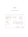
APPENDIX A
Motor Driver Shield Schematics
64
APPENDIX B
The Code to Read the Data from GPS
#include <Adafruit_GPS.h>
#include <SoftwareSerial.h>
SoftwareSerial mySerial(10, 9);
Adafruit_GPS GPS(&mySerial);
#define GPSECHO true
boolean usingInterrupt = false;
void useInterrupt(boolean);
void setup()
{
Serial.begin(115200);
GPS.begin(9600);
GPS.sendCommand(PMTK_SET_NMEA_OUTPUT_RMCONLY);
GPS.sendCommand(PMTK_SET_NMEA_UPDATE_1HZ);
GPS.sendCommand(PGCMD_ANTENNA);
useInterrupt(true);
delay(1000);
}
65
// Interrupt
SIGNAL(TIMER0_COMPA_vect) {
char c = GPS.read();
#ifdef UDR0
if (GPSECHO)
if (c) UDR0 = c;
#endif
}
void useInterrupt(boolean v) {
if (v) {
OCR0A = 0xAF;
TIMSK0 |= _BV(OCIE0A);
usingInterrupt = true;
}
else {
TIMSK0 &= ~_BV(OCIE0A);
usingInterrupt = false;
}
}
uint32_t timer = millis();
int i;
double f;
double f_2;
void loop()
{
if (! usingInterrupt) {
char c = GPS.read();
if (GPSECHO)
if (c) Serial.print(c);
}
if (GPS.newNMEAreceived()) {
if (!GPS.parse(GPS.lastNMEA()))
return;
}
66
if (timer > millis()) timer = millis();
if (millis() - timer > 2000) {
timer = millis(); // reset the timer
// ----------------------------------------------double x= GPS.latitude;
double y= GPS.longitude;
i = x/100;
f= (x-i*100)/100;
f_2 =f*100/60;
x = i + f_2;
i = y/100;
f= (y-i*100)/100;
f_2 =f*100/60;
y = i + f_2;
//-----------------------------------------------Serial.println("*************************************");
Serial.print("\nTime: ");
Serial.print(GPS.hour, DEC); Serial.print(':');
Serial.print(GPS.minute, DEC); Serial.print(':');
Serial.print(GPS.seconds, DEC); Serial.print('.');
Serial.println(GPS.milliseconds);
Serial.print("Date: ");
Serial.print(GPS.day, DEC); Serial.print('/');
Serial.print(GPS.month, DEC); Serial.print("/20");
Serial.println(GPS.year, DEC);
Serial.print("Fix: "); Serial.println((int)GPS.fix);
if (GPS.fix) {
Serial.print("Angle: "); Serial.println(GPS.angle);
Serial.println("");
Serial.println("Location: ");
Serial.print(GPS.latitude, 4); Serial.print(GPS.lat);
Serial.print(", ");
Serial.print(GPS.longitude, 4); Serial.println(GPS.lon);
67
Serial.println("Location in decimal: ");
Serial.print(x, 4); Serial.print(GPS.lat);
Serial.print(", ");
Serial.print(y, 4); Serial.println(GPS.lon);
}
Serial.println("*************************************");
Serial.println("");
Serial.println("");
}
}
68
APPENDIX C
The Code to Finding the Distance and Angle
void setup()
{
Serial.begin(9600);
}
int n=1;
int x,y;
float hea =270;
void loop(){
float distance1=0;
float distance0=0;
float dy=0;
float dx=0;
float way_y []= {1.553802, 1.553740, 1.553740,1.553705,1.553642 }
;
float way_x []= {103.644500, 103.644561, 103.644630, 103.644577, 103.644615} ;
float pyth;
float heading=0;
float angle;
dy=radians(way_y[n]-way_y[n-1]);
way_y[n-1]=radians(way_y[n-1]);
way_y[n]=radians(way_y[n]);
dx=radians((way_x[n])-(way_x[n-1]));
69
distance1 = (sin(dy/2.0)*sin(dy/2.0));
distance0= cos(way_y[n-1]);
distance0*=cos(way_y[n]);
distance0*=sin(dx/2.0);
distance0*=sin(dx/2.0);
distance1 +=distance0;
distance1=(2*atan2(sqrt(distance1),sqrt(1.0-distance1)));
distance1*=6371000.0; //Converting to meters
Serial.print("distance between point "); Serial.print(n-1);
Serial.print(" and point "); Serial.print(n);Serial.println(" is");
Serial.println(distance1);
//print the distance in meters
Serial.println("");
way_x[n-1] = radians(way_x[n-1]);
way_x[n] = radians(way_x[n]);
heading
=
atan2(sin(way_x[n]-way_x[n-1])*cos(way_y[n]),cos(way_y[n-1])*sin(way_y[n])-
sin(way_y[n-1])*cos(way_y[n])*cos(way_x[n]-way_x[n-1])),2*3.1415926535;
heading = heading*180/3.1415926535;
int head =heading;
// convert from radians to degrees
//make it a integer now
if(head<0){
heading+=360;
//if the heading is negative then add 360 to make it positive
}
Serial.println("");
Serial.print("heading from point "); Serial.print(n);
Serial.print(" and point "); Serial.print(n-1);Serial.println(" is");
Serial.println(heading); // print the heading.
Serial.println("");
angle = heading-hea;
hea= heading;
Serial.println("");
Serial.print("angle between point "); Serial.print(n);
Serial.print(" and point "); Serial.print(n-1);Serial.println(" is");
Serial.println(angle); // print the heading.
Serial.println("");
70
Serial.println("**********************************");
n++;
if (n>4) /* *to stop after it finds the distance and angle
*bew=tween last waypoint and target
*/
{
for (int j=3;j>0;j++){}
}
}
71
APPENDIX D
The Code of the Whole Project
#include <Adafruit_GPS.h>
#include <SoftwareSerial.h>
#include <AFMotor.h>
SoftwareSerial mySerial(10, 9);
Adafruit_GPS GPS(&mySerial);
#define GPSECHO true
boolean usingInterrupt = false;
void useInterrupt(boolean);
AF_DCMotor motor_fright(1, MOTOR12_1KHZ);
AF_DCMotor motor_fleft(2, MOTOR12_1KHZ);
AF_DCMotor motor_bright(4, MOTOR12_1KHZ);
AF_DCMotor motor_bleft(3, MOTOR12_1KHZ);
int led_r = 13;
int led_g = 2;
int i = 0;
int n =0;
int x;
int y;
float head_p = 270;
72
void setup()
{
Serial.begin(115200);
GPS.begin(9600);
GPS.sendCommand(PMTK_SET_NMEA_OUTPUT_RMCONLY);
GPS.sendCommand(PMTK_SET_NMEA_UPDATE_1HZ); // 1 Hz update rate
GPS.sendCommand(PGCMD_ANTENNA);
useInterrupt(true);
motor_fright.setSpeed(200);
motor_fleft.setSpeed(200);
motor_bright.setSpeed(200);
motor_bleft.setSpeed(200);
delay(1000);
pinMode(led_r, OUTPUT);
pinMode(led_g, OUTPUT);
}
// Interrupt
SIGNAL(TIMER0_COMPA_vect) {
char c = GPS.read();
#ifdef UDR0
if (GPSECHO)
if (c) UDR0 = c;
#endif
}
void useInterrupt(boolean v) {
if (v) {
OCR0A = 0xAF;
TIMSK0 |= _BV(OCIE0A);
usingInterrupt = true;
}
else {
TIMSK0 &= ~_BV(OCIE0A);
usingInterrupt = false;
}
}
uint32_t timer = millis();
73
void loop()
{
int b;
float f, f_2;
float way_x[6];
float way_y[6];
float distance0=0;
float distance1;
float lon_current, lat_current;
float dy=0;
float dx=0;
float s_tol=0.00001;
float pyth, heading, head;
if(! usingInterrupt)
{
char c = GPS.read();
if (GPSECHO)
if (c) Serial.print(c);
}
if (GPS.newNMEAreceived())
{
if (!GPS.parse(GPS.lastNMEA()))
return;
}
if (timer > millis()) timer = millis();
if (millis() - timer > 2000) {
timer = millis();
if (GPS.fix)
{
/* ------------------------------------------------------For Waypoints
*/
74
if (i<4) {
for(int e=0; e<4;e++){
digitalWrite(led_r, HIGH);
digitalWrite(led_g, LOW);
delay(200);
}
digitalWrite(led_g, LOW);
digitalWrite(led_r, LOW);
delay(200);
way_x [i] = GPS.longitude;
way_y [i] = GPS.latitude;
// Convert GPS coordinates decimal degrees
b = way_x [i]/100;
f= (way_x [i]-b*100)/100;
f_2 =f*100/60;
way_x [i] = b + f_2;
b = way_y [i]/100;
f= (way_y [i]-b*100)/100;
f_2 =f*100/60;
way_y [i] = b + f_2;
delay (1000);
if ( i == 0){
digitalWrite(led_r, HIGH);
delay(500);
digitalWrite(led_r, LOW);
delay(500);
digitalWrite(led_r, HIGH);
delay(500);
digitalWrite(led_r, LOW);
delay(500);
}
75
else if ( i == 1)
{
digitalWrite(led_r, HIGH);
digitalWrite(led_g, HIGH);
delay(500);
digitalWrite(led_r, LOW);
digitalWrite(led_g, LOW);
delay(500);
digitalWrite(led_r, HIGH);
digitalWrite(led_g, HIGH);
delay(500);
digitalWrite(led_r, LOW);
digitalWrite(led_g, LOW);
delay(500);
}
else if ( i == 2)
{
digitalWrite(led_g, HIGH);
delay(500);
digitalWrite(led_g, LOW);
delay(500);
digitalWrite(led_g, HIGH);
delay(500);
digitalWrite(led_g, LOW);
delay(500);
}
else if ( i == 3){
digitalWrite(led_r, HIGH);
digitalWrite(led_g, LOW);
delay(500);
digitalWrite(led_r, LOW);
digitalWrite(led_g, HIGH);
delay(500);
digitalWrite(led_r, HIGH);
digitalWrite(led_g, LOW);
delay(500);
digitalWrite(led_r, LOW);
76
digitalWrite(led_g, HIGH);
delay(500);
digitalWrite(led_r, LOW);
digitalWrite(led_g, LOW);
delay(500);
}
delay (5000);
i++;
}
if (i == 4) {
delay(6000);
for (int h=0; h<5;h++) {
Serial.println();
Serial.println(h+1);
Serial.println("th Waypoint Location is ");
Serial.print("Longitude: "); Serial.println(way_x[h] , 6);
Serial.print("latitude: "); Serial.println(way_y[h] , 6);Serial.println();
digitalWrite(led_r, HIGH);
digitalWrite(led_g, HIGH);
delay(500);
digitalWrite(led_r, LOW);
digitalWrite(led_g, LOW);
delay(500);
}
i++;
}
if (i > 4)
{
lon_current = GPS.longitude;
lat_current = GPS.latitude;
77
b = lon_current/100;
f= (lon_current-b*100)/100;
f_2 =f*100/60;
lon_current = b + f_2;
b = lat_current/100;
f= (lat_current-b*100)/100;
f_2 =f*100/60;
lat_current = b + f_2;
dy=radians(way_y [n]-lat_current);
lat_current=radians(lat_current);
way_y [n]=radians(way_y [n]);
dx=radians((way_x [n])-(lon_current));
s_tol= radians(s_tol);
distance1 = (sin(dy/2.0)*sin(dy/2.0));
distance0= cos(lat_current);
distance0*=cos(way_y [0]);
distance0*=sin(dx/2.0);
distance0*=sin(dx/2.0);
distance1 +=distance0;
distance1=(2*atan2(sqrt(distance1),sqrt(1.0-distance1)));
distance1*=6371000.0;
//Converting to meters
Serial.println("");Serial.println("");
Serial.println("-----------------------------------");
Serial.print("distance ");
Serial.println(n);
Serial.println(distance1);
//print the distance in meters
Serial.println("-----------------------------------");
lon_current = radians(lon_current);
way_x[n] = radians(way_x[n]); //radians duh.
heading = atan2(sin(way_x[n]-lon_current)*cos(way_y[n]),cos(lat_current) *sin(way_y[n])
-sin(lat_current)*cos(way_y[n])*cos(way_x[n]-lon_current)) ,2*3.1415926535;
78
heading = heading*180/3.1415926535; // convert from radians to degrees
int header =heading; //make it a integer now
if(header<0){
heading+=360; //if the heading is negative then add 360 to make it positive
}
Serial.println("");
Serial.println("heading:");
Serial.println(heading); // print the heading.
Serial.println("");
Serial.println("");
Serial.println("");
Serial.println("");
head = heading - head_p;
head_p = heading;
if (head >0)
{
//turn right
motor_fright.run(RELEASE);
motor_fleft.run(FORWARD);
motor_bright.run(RELEASE);
motor_bleft.run(FORWARD);
x= head*50;
delay (x);
// Move Forward
motor_fright.run(FORWARD);
motor_fleft.run(FORWARD);
motor_bright.run(FORWARD);
motor_bleft.run(FORWARD);
y=distance1*4000;
delay (y);
}
79
else if (head <0)
{ //turn left
motor_fright.run(FORWARD);
motor_fleft.run(RELEASE);
motor_bright.run(FORWARD);
motor_bleft.run(RELEASE);
head = 0-head;
x= head*50;
delay (x);
// Move Forward
motor_fright.run(FORWARD);
motor_fleft.run(FORWARD);
motor_bright.run(FORWARD);
motor_bleft.run(FORWARD);
y=distance1*4000;
delay (y);
}
else if (head == 0)
{
// Move Forward
motor_fright.run(FORWARD);
motor_fleft.run(FORWARD);
motor_bright.run(FORWARD);
motor_bleft.run(FORWARD);
y=distance1*4000;
delay (y);
}
for(int e=0; e<4;e++){
digitalWrite(led_g, HIGH);
delay(100);
digitalWrite(led_g, LOW);
delay(100);
}
n++;
80
if (n>3){
motor_fright.run(RELEASE);
motor_fleft.run(RELEASE);
motor_bright.run(RELEASE);
motor_bleft.run(RELEASE);
for(int e=0; e<4;e++){
digitalWrite(led_r, HIGH);
digitalWrite(led_g, LOW);
delay(100);
digitalWrite(led_r, LOW);
digitalWrite(led_g, HIGH);
delay(100);
}
digitalWrite(led_r, LOW);
digitalWrite(led_g, LOW);
delay(100);
}
}
}
}
}
for (int h=1 ; h>0;h++){}