1
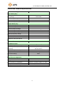
ALTENERGY POWER SYSTEM, INC. APS M1P Single-phase Micro-inverter Installation and User Manual Version: 1.0 ALTENERGY POWER SYSTEM, INC. All rights reserved 1 ALTENERGY POWER SYSTEM, INC. Contact Information ALTENERGY POWER SYSTEM Inc. 1 Yatai Road, Jiaxing, PR China 314050 Phone: +86-21-68889199 Fax: +86-21-33928752 www.altenergy-power.com [email protected] 2 ALTENERGY POWER SYSTEM, INC. Table of Contents 1. Important Safety Information ........................................................................ Error! Bookmark not defined. Safety Instructions ............................................................................................. Error! Bookmark not defined. 2. APS Micro-inverter System Introduction ...................................................... Error! Bookmark not defined. 3. APS Single-phase Micro-inverter M1P series Introduction .................. Error! Bookmark not defined. 4. APS Micro-inverter System Installation ........................................................ Error! Bookmark not defined. Installation Kits from APS .................................................................................................................................. 9 Required Parts and Tools .................................................................................................................................... 9 Installation Procedures ....................................................................................... Error! Bookmark not defined. Step 1 –Installing the AC Branch Circuit Junction Box .................................................................................11 Step 2 –Attaching the APS Micro-inverters to the Racking or the PV Module FrameError! Bookmark not defined. Step 3 - Connecting the APS Micro-inverter AC Cables .............................................................................. 13 Step 4 - Connecting APS Micro-inverters to the PV Module ....................................................................... 12 Step 5 - Completing the APS Installation Map .............................................. Error! Bookmark not defined. 5. APS micro-inverter system operating instructions ........................................ Error! Bookmark not defined. 6. Troubleshooting ............................................................................................. Error! Bookmark not defined. Startup LED .................................................................................................................................................. 14 Operation LED ............................................................................................................................................. 14 Other Faults ................................................................................................... Error! Bookmark not defined. Troubleshooting a Non-operating APS Micro-inverter ...................................... Error! Bookmark not defined. 7. Replacing a Micro-inverter ........................................................................................................................... 15 8. Technical Data ............................................................................................... Error! Bookmark not defined. YC250-SAA Technical Specifications .......................................................................................................... 14 YC500-SAA Technical Specifications .......................................................................................................... 19 9. Appendix ...................................................................................................................................................... 20 9.1 Sample Wiring Diagram – Single Phase .............................................................................................. 20 9.2 Sample Wiring Diagram – Three Phase ................................................ Error! Bookmark not defined. 9.3 Installation Map Template .................................................................... Error! Bookmark not defined. 3 ALTENERGY POWER SYSTEM, INC. 1. Important Safety Information This manual contains important instructions to follow during installation and maintenance of the APS Photovoltaic Grid-connection Micro-inverter. To reduce the risk of electrical shock and ensure the safe installation and operation of the APS Micro-inverter, the following symbols appear throughout this document to indicate dangerous conditions and important safety instructions. WARNING: This indicates a situation where failure to follow instructions may cause a serious hardware failure or personnel danger if not applied appropriately. Use extreme caution when performing this task. NOTE: This indicates information that is important for optimized Micro-inverter operation. Follow these instructions closely. Safety Instructions Only qualified professionals should install and/or replace APS Micro-inverters. Perform all electrical installations in accordance with local electrical codes. Before installing or using the APS Micro-inverter, please read all instructions and cautionary markings in the technical documents and on the APS Micro-inverter system and the PV-array. Be aware that the body of the APS Micro-inverter is the heat sink and can reach a temperature of 80°C. To reduce risk of burns, do not touch the body of the Micro-inverter. Do NOT disconnect the PV module from the APS Micro-inverter without first disconnecting the AC power. Do NOT attempt to repair the APS Micro-inverter. If it fails, contact APS Customer Support to obtain an RMA number and start the replacement process. Damaging or opening the APS Micro-inverter will void the warranty. 4 ALTENERGY POWER SYSTEM, INC. 2. APS Micro-inverter System Introduction The APS Micro-inverter is an inverter system for use in utility-interactive applications, comprised of three key elements: Altenergy Power Systems Micro-inverter Altenergy Power Systems Energy Communication Unit (ECU) Altenergy Power Systems Energy Monitor and Analysis (EMA) web-based monitoring and analysis system Meter Distribution Box PV Module Micro-inverter ECU Neutral Ground Outlet Internet EMA This integrated system improves safety; maximizes solar energy harvest; increases system reliability; simplifies photovoltaic (PV) system design, installation, maintenance, and management. The APS Micro-inverters maximize energy production from photovoltaic (PV) arrays. Each PV module has individual Maximum Peak Power Tracking (MPPT) controls, which ensures that the maximum power is exported to the utility grid regardless of the performance of the other PV modules in the array. When PV modules in the array are affected by shading, soiling, orientation, or mismatch, the APS Micro-inverter ensures top 5 ALTENERGY POWER SYSTEM, INC. performance from the array by maximizing the performance of each module within the array. The APS Micro-inverter system is more reliable than centralized or string inverters. The distributed Micro-inverter system ensures that no single point of system failure exists across the PV system. APS Micro-inverters are designed to operate at full power at ambient temperatures of up to 65°C. The inverter housing is designed for outdoor installation and complies with the IP65 environmental enclosure rating. PV systems using APS Micro-inverters are very simple to install. You can install individual PV modules in any combination of module quantity, orientation, type, and power rate. The Ground wire (PE) of the AC cable is connected to the chassis inside of the Micro-inverter, eliminating the installation of grounding wire. The APS Micro-inverter system provides smart system performance monitoring and analysis. The APS Energy Communication Unit (ECU) is installed by simply plugging it into any wall outlet and providing an Ethernet or Wi-Fi connection to a broadband router or modem. After installing the ECU, the full network of APS Micro-inverters automatically reports to the APS Energy Monitor and Analysis (EMA) web server. The EMA software displays performance trends, informs you of abnormal events, and controls system shutdown when it is needed. 6 ALTENERGY POWER SYSTEM, INC. 3. APS Single-phase Micro-inverter M1P series Introduction The APS M1P series Micro-inverters connect with the single-phase grid, and operate with most 60 and 72 cell PV modules. For more information, please see the section 8 Technical Date of this manual. Model Max. # AC grid PV Module YC250-SAA 50Hz/230V 60,72 Cell 22 MC-4 Type or Customize YC500-SAA 50Hz/230V 60,72 Cell 11 MC-4 Type or Customize Number Per branch 7 Module Connector ALTENERGY POWER SYSTEM, INC. The following figure shows the APS YC250 micro-inverter schematic: APS YC500 has two independent DC inputs, with independent MPPT control and date monitoring. The following figure shows the APS YC500 micro-inverter schematic: 8 ALTENERGY POWER SYSTEM, INC. 4. APS Micro-inverter System Installation A PV system using APS Micro-inverters is simple to install. Each Micro-inverter easily mounts on the PV racking, directly beneath each PV module. Low voltage DC wires connect from the PV module directly to the Micro-inverter, eliminating the risk of high DC voltage. Installation shall comply with local regulations and technical rules. Installation shall comply with the relevant instructions of AS 4777.1 & AS 3000. WARNING: Perform all electrical installations in accordance with local electrical codes. WARNING: Be aware that only qualified professionals should install and/or replace APS Micro-inverters. WARNING: Before installing or using an APS Micro-inverter, please read all instructions and warnings in the technical documents and on the APS Micro-inverter system itself as well as on the PV array. WARNING: Be aware that installation of this equipment includes the risk of electric shock. WARNING: Do not touch any live parts in the system, including the PV array, when the system has been connected to the electrical grid. Installation Kits from APS APS micro-inverter installation kit includes following items: An AC interconnect cable Protective end caps Required Parts and Tools from you In addition to your PV array and its associated hardware, you need to provide the following: An AC connection junction box Mounting hardware suitable for module racking Sockets and wrenches for mounting hardware Continuous grounding conductor and grounding washers A Phillips screwdriver A torque wrench 9 ALTENERGY POWER SYSTEM, INC. Installation Procedures Installing the APS Micro-inverter System involves 5 key steps: 1. Attaching the APS Micro-inverters to the racking or the PV module frame. 2. Connecting the APS Micro-inverter AC cables. 3. Connect the Micro-inverters to the PV modules. 4. Installing the AC branch circuit junction box. 5. Completing the APS installation map. WARNING: Do NOT connect APS Micro-inverters to the utility grid or energize the AC circuit until you have completed all of the installation procedures as described in the following sections. For bracket installation, after the completion of system installation rendering as follows: Joint distribution box 10 ALTENERGY POWER SYSTEM, INC. Step 1 - Installing the AC Branch Circuit Junction Box a. Install an appropriate junction box at a suitable location on the PV racking system (typically at the end of a branch of modules). b. Connect the open wire end of the AC interconnect cables into the junction box using an appropriate gland or strain relief fitting. c. Wire the conductors: L- RED; N - BLACK; PE – YELLOW GREEN. d. Connect the AC branch circuit junction box to the point of utility interconnection. NOTE: Be sure to size the AC wire to account for voltage drop between the AC branch circuit junction box and the point of utility interconnection. Maximum external wiring distance (meter) 2 Wire (mm ) 2.5 4 6 10 16 10 23 37 59 94 149 Module number in branch 11 12 13 17 14 11 26 22 18 42 35 29 67 55 45 106 88 72 14 9 14 23 37 58 15 7 11 18 28 45 Step 2 – Attaching the APS Micro-inverters to the Racking or the PV Module Frame 11 ALTENERGY POWER SYSTEM, INC. a. Mark the location of the Micro-inverter on the rack, with respect to the PV module junction box or any other obstructions. b. Mount one Micro-inverter at each of these locations using hardware recommended by your module racking vendor. WARNING: Prior to installing any of the micro-inverters, verify that the utility voltage at the point of common connection matches the voltage rating on micro-inverter label. WARNING: Do not mount the Micro-inverter in a location that allows exposure to direct sunlight. Allow a minimum of 1.5 centimeters between the top of the roof and the bottom of the Micro-inverter. Step 3 - Connecting the APS Micro-inverter AC Cables a. Check the Micro-inverter rating label for the maximum allowable number of Micro-inverters on one AC branch circuit. b. Plug the AC female connector of the first Micro-inverter into the male connector of the next Micro-inverter, and so on, to form a continuous AC branch circuit. c. Install a protective end cap on the open AC connector of the last Micro-inverter in the AC branch circuit. WARNING: Do NOT exceed the maximum number of Micro-inverters in an AC branch circuit, as displayed on the unit label. 12 ALTENERGY POWER SYSTEM, INC. Step 4 –Connecting APS Micro-inverters to the PV Module Photovoltaic panels and micro-inverter DC input cable connection according to demand. - + +WARNING: Ensure that all AC and DC wiring is correct. Ensure that none of the AC and DC wires are pinched or damaged. Ensure that all junction boxes are properly closed. NOTE: Step 1~4 can change sequence for convenience of installation. Step 5 - Completing the APS Installation Map The APS Installation Map is a diagram of the physical location of each Micro-inverter in your PV installation. You can use the blank map in the Appendix to record Micro-inverter placement for your system. When your map is complete, send it to APS as described below. APS uses this information to provide you with detailed information about the performance of your PV system and to allow you to see a graphic representation of your PV system on APS’s EMA web-based monitoring and analysis system. Feel free to provide your own layout if a larger or more intricate installation map is required. a. Each APS Micro-inverter has a removable serial number label located. Peel the label off, and affix it to the respective location on the APS installation map, which is available in the Appendix section of this manual or on the APS website at www.altenergy-power.com/quickstart. b. Send the installation map to APS after completion. c. After APS creates a graphical view of your PV system on the EMA website, use the EMA website to view detailed performance information for your PV system. Please go to www.altenergy-power.com for more information on APS’s EMA web-based monitoring and analysis system. 13 ALTENERGY POWER SYSTEM, INC. 5. APS micro-inverter system operating instructions To operate the APS micro-inverter PV system: 1. Turn ON the AC circuit breaker on each micro-inverter AC branch circuit. 2. Turn ON the main utility-grid AC circuit breaker. Your system will start producing power after a two-minute wait time. Note: once DC power is applied, the Status LED of each micro-inverter will blink green three times to indicate normal start-up operation. 3. The APS micro-inverters will start to send performance data over power line to the ECU. The time required for all the micro-inverters in the system to report to the ECU will vary with the number of micro-inverters in the system. You can verify proper operation of the APS micro-inverters via the ECU. See the ECU Installation and Operation Manual for more information. 6. Troubleshooting Qualified personnel can use the following troubleshooting steps if the PV system does not operate correctly. Status Indications and Error Reporting Startup LED When DC power is first applied to the micro-inverter: Three short green blinks when DC power is first applied to the micro-inverter indicate a successful micro-inverter startup Operation LED Flashing Slow Green (10s gap) - Producing power and communicating with ECU Flashing Fast Green (2s gap) – Producing power and not communicating with ECU Flashing Red – Not producing power Other Faults All other faults are reported to the ECU. Refer to the ECU Installation and Operation Manual for a list of additional faults and troubleshooting procedures. WARNING: Be aware that only qualified personnel should troubleshoot the APS micro-inverter. 14 ALTENERGY POWER SYSTEM, INC. WARNING: Never disconnect the DC wire connectors under load. Ensure that no current is flowing in the DC wires prior to disconnecting. An opaque covering may be used to cover the module prior to disconnecting the module. WARNING: Always disconnect AC power before disconnecting the PV module wires from the APS micro-inverter. The AC connector of the first micro-inverter in a branch circuit is suitable as a disconnecting means once the AC branch circuit breaker in the load center has been opened. WARNING: The APS micro-inverter is powered by PV module DC power. Make sure you disconnect and reconnect the DC connections to watch for the three short LED flashes. Troubleshooting a non-operating APS micro-inverter To troubleshoot a non-operating APS micro-inverter, follow the steps below in order: 1. Verify the utility voltage and frequency are within ranges shown in the in section 8 Technical Data of this manual. 2. Check the connection to the utility grid. Verify utility power is present at the inverter in question by removing AC, then DC power. Never disconnect the DC wires while the micro-inverter is producing power. Re-connect the DC module connectors and watch for three short LED flashes. 3. Check the AC branch circuit interconnection between all the micro-inverters. Verify each inverter is energized by the utility grid as described in the previous step. 4. Make sure that any AC breaker are functioning properly and are closed. 5. Check the DC connections between the micro-inverter and the PV module. 6. Verify the PV module DC voltage is within the allowable range shown in the Section 8 Technical Data of this manual. 7. If the problem persists, please call APS Energy customer support. WARNING: Do not attempt to repair the APS micro-inverter. If troubleshooting methods fail, please return the micro-inverter to your distributor for replacement. 15 ALTENERGY POWER SYSTEM, INC. 7. Replace a micro-inverter Follow the procedure to replace a failed APS micro-inverter. 1. Disconnecting the APS micro-inverter from the PV Module, in the order shown below: 1) Disconnect the AC by opening the branch circuit breaker. 2) Cover the module with an opaque cover. 3) Disconnect the first AC connector in the branch circuit. 4) Disconnect the PV module DC wire connectors from the micro-inverter. 5) Remove the micro-inverter from the PV array racking. 2. Install a replacement micro-inverter to the rack. 3. Connect the AC cable of the replacement micro-inverter and the neighboring micro-inverters to complete the branch circuit connections. 4. Close the branch circuit breaker, and verify operation of the replacement micro-inverter. 16 ALTENERGY POWER SYSTEM, INC. 8. Technical Data WARNING: Be sure to verify the voltage and current specifications of your PV module match with those of the micro-inverter. Refer to the APS website http://www.altenergy-power.com for a list of approved PV modules. WARNING: You must match the DC operating voltage range of the PV module with the allowable input voltage range of the APS micro-inverter. WARNING: The maximum open circuit voltage of the PV module must not exceed the specified maximum input voltage of the APS micro-inverter. 17 ALTENERGY POWER SYSTEM, INC. YC250-SAA Technical Specifications Type YC250-SAA Input Data (DC) Recommended PV Module Power (STC)Range 180W-280W MPPT Voltage Range 22V-45V Maximum Input Voltage 55V Maximum Input Current 12A Output Data (AC) Maximum Output Power 250W Maximum Output Current 1.09A Nominal Output Voltage 230V Output Voltage Range 187V-242V Nominal Output Frequency 1 50Hz 1 Output Frequency Range 49.5Hz-50.2Hz Power Factor >0.99 Total Harmonic Distortion <3% Maximum units per branch 22 Efficiency Peak inverter efficiency 95.0% Mechanical Data Storage temperature range Operating temperature o o o range (Ambient) Dimensions (W x H x D) o -40 C to +85 C -40 C to +65 C 160mmX 150mmX 29mm Weight 1.5kg Enclosure Rating IP65 Cooling Natural Convection Features & Compliance Communication Powerline Design lifetime 25yrs Grid connection compliance AS4777.2:2005; AS4777.3:2005 Safety class compliance 1 AS/NZS 3100:2009 Programmable through ECU to meet customer need. 18 ALTENERGY POWER SYSTEM, INC. YC500- SAA Technical Specifications Type YC500-SAA(for 2 panels) Input Data (DC) Recommended PV module power (STC) range 180W-280W MPPT voltage range 22V-45V Maximum input voltage 55V Maximum input current 12 Ax 2 Output Data (AC) Rated output power 500W Max. Output current 2.17A Nominal output voltage 220V output voltage range 187V-242V Nominal output frequency 1 50Hz 1 Output frequency range 49.5Hz-50.2Hz Power factor >0.99 Total Harmonic Distortion <3% Maximum units per branch 11 Efficiency Peak inverter efficiency 95.5% Mechanical Data Storage temperature range Operating temperature -40ºC to +85ºC range o (Ambient) Dimensions (W x H x D) o -40 C to +65 C 220mm X 160mm X 29mm Weight 2.5kg Enclosure Rating IP65 Cooling Natural Convection Features & Compliance Communication Powerline Design lifetime 25yrs Grid connection compliance AS4777.2:2005; AS4777.3:2005 Safety class compliance 1 AS/NZS 3100:2009 Programmable through ECU to meet customer need. 19 ALTENERGY POWER SYSTEM, INC. 9. Appendix 9.1 Sample Wiring Diagram – Single Phase YC250 Up to 22 units YC500 to 11 units Up Up to 15 units PV Module Micro-inverter Meter Distribution Box ECU Neutral Ground Outlet Internet EMA 20 ALTENERGY POWER SYSTEM, INC. 9.2 Sample Wiring Diagram – Three Phase Three phase breaker A Three phase distribution box B C N Micro-inverters phase A Micro-inverters phase B Micro-inverters phase C ECU Neutral Ground EMA Internet Note: The ECU will also function properly when connected to phase B or phase C. 21 ALTENERGY POWER SYSTEM, INC. 9.3 Installation Map Template 1 2 3 A B C D E F G H I J K L M N O 22 4