1
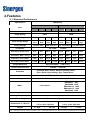
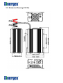
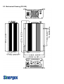
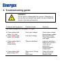
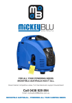
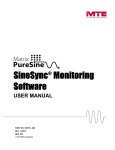
PureSine 150/300
Pure Sine Wave Inverter
User’s Manual
1. Important Safety Instructions
WARNING!
Before you install and use your Inverter, please read and
follow these safety instructions.
1-1. General Safety Precautions
1-1-1. Do not expose the Inverter to rain, snow, spray, bilge or dust.
To reduce risk of hazard, do not obstruct the ventilation
openings. Do not install the Inverter in a zero-clearance
compartment as overheating may result.
1-1-2. To avoid the risk of fire and electric shock ensure all wiring and
and cables are in good electrical conditions and of sufficient size.
Do not operate the Inverter with damaged or substandard wiring.
1-1-3. The PS-150/300 contains components which can produce arcs or
sparks.
To prevent fire or explosion, do not install or use in
compartments containing batteries, flammable materials or in locations
that require ignition protected equipment.
This includes any space
containing gasoline-powered machinery, fuel tanks, joints, fittings,
or other connections or components of any fuel system.
1-2. Precautions When Working with Batteries
1-2-1. If battery acid contacts skin or clothing, wash immediately with soap
and water. If acid enters eyes, immediately flood eyes with running
cold water for at least 20 minutes and get immediate medical attention.
1-2-2. Never smoke or allow a spark or flame in the vicinity of the battery or
engine.
1-2-3. Do not drop any metal tools or equipment on the battery. Doing so may
result in sparking or the short circuit of the battery or possible explosion.
1-2-4. Remove personal metal items such as rings, bracelets, necklaces,
and watches when working with a lead-acid battery.
A lead-acid battery can produces a short-circuit current high enough
to weld a ring or the like to metal, causing severe burns.
2.Features
2-1. Electrical Performance
Model No.
Specification
Item
S150 - XXX
112
124
S300 - XXX
212
224
112
124
212
Continuous Output Power
150W
300W
Surge Rating
300W
500W
224
Input voltage
12V
24V
12V
24V
12V
24V
12V
24V
Input Voltage Range
10.5 –
15.0
21.0 –
30.0
10.5 –
15.0
21.0 –
30.0
10.5 –
15.0
21.0 –
30.0
10.5 –
15.0
21.0 –
30.0
Output Voltage
110 VAC ±5%
230 VAC ±5%
Frequency
50 / 60Hz
110 V VAC ±5%
230 VAC ±5%
± 0.05%
Efficiency (Peak Load)
91%
92%
90%
93%
92%
93%
91%
94%
Efficiency (Max. / Avg.)
86%
87%
85%
88%
87%
88%
86%
89%
Efficiency (Full Load)
72%
79%
72%
80%
72%
78%
72%
80%
No Load Current Draw
0.18A
0.15A
0.22A
0.16A
0.26A
0.23A
0.23A
0.15A
Output Waveform
Pure Sine Wave ( THD < 4% )
Power Factor Allowed
cosθ-90° ~ cosθ+90°
Protection
Overload, Short Circuit, Reverse Polarity (Fuse),
Over / Under Input Voltage, Over Temperature.
Remote Control
Yes, On/Off controlled by external switch
Safety*
UL458
EMC**
FCC Class B
EN60950
EN50081-1 1992
EN50082-1 1992
EN55022B 1994
EN61000-4-2 1995
EN61000-4-3 1996
ENV50204 1995
Operating Temperature
0* – 40* C
Storage Temperature
-30* to 70* C
Fan Cooling
Thermostatically controlled
Dimensions (L x W x H)
Weight
200 x 132 x 72 mm
237 x 155 x 72 mm
7.87 x 5.20 x 2.83 inch
9.33 x 6.10 x 2.83 inch
2.7 Kgs.
/
5.4 Lbs.
3.5 Kgs.
/
7.7 Lbs.
*110V mode design meets UL 458 & FCC Class B. **230V model design meets CE & “e “ Mark. (Currently, all applied projects are pending)
2-2. Mechanical Drawing (PS-150)
Sinergex
2-3. Mechanical Drawing (PS-300)
Sinergex
3. Introduction
The Sinergex PureSine series are of the most, reliable, and high performing true
sine wave inverters available. The PureSine inverters can be used in wide range of
applications including portable office equipment, home entertainment products,
computers and most AC powered products within each models size capabilities.
To ensure maximum performance from your Sinergex PureSine inverter it must
be installed and used correctly Please carefully read and follow the instructions
in this manual before installation and operation of your inverter.
3-1. Front Panel Operations
3-1-1. ON / OFF/ REMOTE switch
Leave the Power ON / OFF / REMOTE switch in the OFF position during
installation.
3-1-2 LED display indicates Power Status
LED
Conditions
Solid Green
Blinked Red fast
Blinked Red slowly
Blinked Red
intermittently
Solid Red
Status
AC Power OK
OVP
UVP
OTP
OLP
3-1-3. Remote Port: Placing 0.75mm2 and Screw type wiring connecting the
remote Port and remote panel.
3-2. Rear Panel Operations
3-2-1. Ventilation window: Do not obstruct. Allow at least 3 inches of
clearance for airflow.
3-2-2. Input terminals: Connect 12V / 24V batteries or other 12V / 24V power
sources. Red is positive, Black is negative. Reverse polarity
connection will blow internal fuse and may damage inverter
permanently and void warranty.
3-2-3. Using # 8 AWG wire connects Chassis ground and Vehicle Chassis.
4
WARNING!
Do not connect the 12V model to a 24V battery;
the unit will be destroyed immediately.
Operation of the inverter without a proper ground
connection may result an electrical safety hazard.
Damage caused by reversed polarity is not covered by
warranty. Make sure the power switch is in the
OFF position before connecting to the battery.
3-3. AC Safety Grounding:
During the AC wiring installation, AC input and output ground wires are
connected to the inverter. The AC input ground wire must connect to the
incoming ground of your AC utility source.
The AC output ground wire should go to the grounding point for your loads
( for example, a distribution panel ground bus ).
3-3-1. Neutral Grounding (GFCI’S):
110V models: The neutral conductor of the AC output circuit of the Inverter is
automatically connected to the safety ground during inverter operation.
This conforms to National Electrical Code requirements that separately derived
AC sources (such as inverter and generators) have their neutral conductors
tied to ground in the same way that the neutral conductor from the utility is tied
to ground at the AC breaker panel. For models configured with a transfer
relay, while AC utility power is presenting and the inverter is in bypass mode,
this connection (neutral of the Inverter’s AC output to input safety ground) is
not present so that the utility neutral is only connected to ground at your
breaker panel, as required. Sinergex has tested the following GFCI –
protected 20A receptacles and found that they functioned properly when
connected to the output of the Inverter
WARNING!
Never connect the inverter’s output to the AC distribution
grid, such as your household AC wall outlet.
Doing so will damage the Inverter and void warranty.
3-4. Installation
Before connecting your applications to the inverter, always check the power
draw of your appliances. The inverter will supply a greater surge power for a
short time to start electrical equipment such as electric motors, pumps etc., that
require more power while starting up.
When all the above requirements are satisfied and all connections are made,
it’s the time to turn on your inverter by pushing the power switch to the ‘ I ’
position. The sine wave output AC voltage gently rises from AC outlet.
When the inverter is not supplying power to an application for a prolonged
period of time, it’s recommended to turn off the inverter to save your batteries,
since the inverter still draws a very small amount of current when there is no
load connected.
DC input voltage status as follows:
DC Input over
Voltage
Model
DC Input under
Voltage
Shut-down
Restart
Shut-down
Restart
12V models
15.3
14.8
10.5
12.5
24V models
30.6
29.6
21.0
25.0
4. Troubleshooting guide:
WARNING!
Do not open or disassemble the inverter. Attempting to
service the unit yourself may result in a risk of electrical
shock or fire and void warranty.
Problems and Symptoms
Possible Cause
No output voltage, the LED glows RED light.
Solutions
a. Power status light
blinks RED fast.
b. Power status light
blinks RED slowly.
Over input voltage.
Check input voltage.
Reduce input voltage.
Recharge battery.
Check connections
and cable.
c. Power status light is
blinks RED
intermittently.
Thermal shutdown
Improve ventilation.
Make sure inverter’s
vents are not
obstructed.
Reduce ambient
temperature.
d. Power status light
glow steady RED.
Short circuit, Wiring
error.
Over Load
Check AC wiring
for short circuit.
Remove load.
Low input voltage.