1
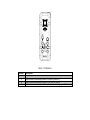
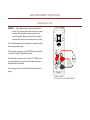
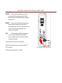
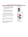
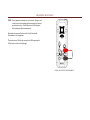
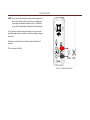
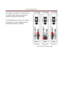
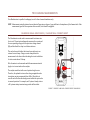
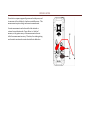
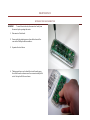
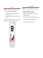
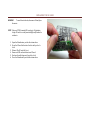
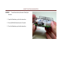
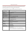
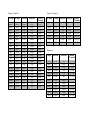
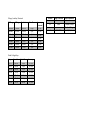
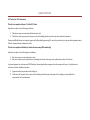
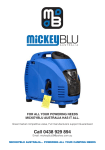
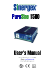
MOOSHIMETER USER’S MANUAL Mooshim Engineering, LLC 2565 3rd St, Suite 315 San Francisco, CA, 94107 August 2014, Rev 1 © 2014 Mooshim Engineering, All Rights Reserved INTRODUCTION The Mooshim Mooshimeter BLE-DMM-2X-01A (hereafter “The Meter”) is a battery powered multimeter capable of handheld and remote usage via Bluetooth Low Energy. This manual details how to safely use your Mooshimeter. The Meter meets CAT III IEC 61010-1 3rd edition and 61010-2-030 standards. Overvoltage category III (CAT III) defines a level of safety appropriate for the transient overvoltages present in fixed equipment installations at the distribution level. This includes the mains installation of a building, distribution boards, busbars, and permanently connected equipment. Do not use this multimeter for CAT IV circuits, which includes any mains circuits not protected by a building’s breakers. PACKAGE CONTENTS Mooshimeter (1) o 1.5V AA Alkaline Batteries installed (2) o 12A HRC fuse installed (1) Test Leads (3) Alligator Clip Attachment (3) Carrying case (1) SAFETY INFORMATION WARNING Denotes a potentially hazardous situation that may result in injury or death CAUTION Denotes a potentially hazardous situation that may result in damage to the meter NOTE Denotes a situation that may result in degraded or incorrect measurement Use caution in the operation of this device. Improper use may result in injury or death. Read this user manual before operating the meter. Always remove leads before opening the case. Do not operate the meter unless it is fully assembled with both case screws tight. Only use appropriately rated fuses. Always check for damage before use. Pay special attention to the test leads for signs of damaged insulation or exposed conductors. Immediately replace damaged leads. Only use test leads that are rated to at least CAT III 600V. Keep fingers behind the guards on the leads. Use caution working with voltages above 30VAC rms, 42VAC peak, or 60VDC. Voltages this high pose risk of shock. Never apply more than 600V between any terminal and earth ground. Do not apply more than 2.0V to the auxiliary terminal with respect to Common. Doing so may draw unexpected current and trigger protection circuits. In this event, basic functionality will automatically return within one minute. Accuracy may be adversely affected for up to five minutes. Error messages may appear on the user interface. Read these messages for further information. TABLE 1 SYMBOLS Caution: Risk of Electric Shock. Refer to operating instructions. Important Information: Refer to operating instructions. CAT III This instrument is rated for installation category III per IEC 61010. Double Insulation Terminal protected by fuse. Current limit of 10A RMS. Conforms to European Union Directives Do not exceed 600V with respect to ground. TABLE 2 TERMINALS Terminal C V A Ω Description Common terminal for all measurements Input terminal for measuring currents to 10A RMS (AC and DC) Input terminal for measuring voltages to 600V RMS (AC and DC) Input terminal for measuring resistance, diode drop, and voltages up to 1.2V BASIC MEASUREMENT INSTRUCTIONS MEASURING VOLTAGE WARNING Risk of Electrocution. For determining whether a circuit is “live” exercise caution if the meter does not report a voltage. This may indicate a poor connection to the circuit being tested. Make sure the probe tips are fully in contact with the circuit before assuming the circuit is safe. Two of the Mooshimeter’s input terminals are capable of making basic voltage measurements: The V terminal can measure up to 600V RMS and is intended for traditional AC and DC voltage measurements. The Ω terminal can measure up to 1V peak (~0.7V RMS for puresine AC) and allows for several new measurement techniques described later in this manual. See the ratings section for further details on the measurement ranges. FIGURE 1 BASIC VOLTAGE MEASUREMENT MEASURING CURRENT WITH INTERNAL CURRENT SHUNT WARNING Exercise care when connecting in series with a circuit, especially those containing motor(s). Sudden disconnects may create higher than expected voltages due to inductive kick. WARNING Perform a Fuse Check before measuring currents with the internal current shunt. Exercise caution in determining whether a circuit is “live” if the meter does not report a current. This may indicate either a poor connection or a blown fuse. NOTE AC current range is limited by the instantaneous current. Peaks above the listed limits will result in incorrect readings. Derate AC current limits with high crest factors accordingly. Disconnect power from the circuit to be measured. Break the circuit and wire the meter in series through the “A” and “C” terminals. Positive DC current flows into the “A” terminal. FIGURE 2 BASIC CURRENT MEASUREMENT MEASURING CURRENT WITH AN EXTERNAL CURRENT SHUNT WARNING This measurement mode is capable of measuring currents many orders of magnitude larger than is typically possible with a handheld meter. Exercise caution while interfacing to high ampacity circuits. NOTE The accuracy of this measurement mode depends on the accuracy of the external current shunt used. Account for this accuracy dependency in your measurements. The Ω terminal can measure small voltages, with a resolution of as fine as 25nV per count and a noise floor as low as 1µV. This can be used to with external current shunts to measure currents over a very wide dynamic range. See the ratings section to guide shunt size selection. It is possible to use the existing wiring for the current shunt, and in doing so take rough current measurements without breaking the circuit. With very low voltages it is recommended to minimize the loop area of the measurement probes by either twisting them together or using a BNC adaptor. FIGURE 3 EXTERNAL CURRENT SHUNT MEASURING RESISTANCE NOTE Do not measure resistance on a live circuit. Doing so will result in incorrect readings and may engage the internal protection circuitry. Should this occur, wait 5 minutes before taking further measurements. Resistance is measured between the Ω and C terminals. Polarization is not important. The meter uses a 100nA test current in its MΩ ranges and a 100uA test current in its kΩ ranges. FIGURE 4 RESISTANCE MEASUREMENT DIODE TESTING NOTE Do not use the diode test functionality while connected to a live circuit. Doing so will result in incorrect readings and may engage the internal protection circuitry. Should this occur, wait 5 minutes before taking further measurements. To test diodes or other silicon junction devices, a test current is pushed through the device under test and the resulting voltage is measured. Positive test current flows out of the Ω terminal and into the C terminal. The test current is 100µA. FIGURE 5 DIODE MEASUREMENT USING A BNC ADAPTER The 4 terminals are arranged with 0.75” spacing to allow for use of a standard BNC adapter. Measurements using the A or Ω terminals can be used with the C terminal as usual. To use a BNC adapter with the “V” input, use the “A” terminal as the common input. The “A” and “C” terminals are internally connected with a low impedance (<=20mOhms). FIGURE 6 BNC ADAPTORS FOR Ω, V, A INPUTS TWO CHANNEL MEASUREMENTS Your Mooshimeter is capable of reading any two of its three channels simultaneously. NOTE Measurements using the internal current shunt will experience a degree of cross-talk due to the impedence of the Common lead. Other measurement types will also experience this cross-talk, but it should be negligible. MEASURING SMALL RESISTANCES / CALIBRATING A CURRENT SHUNT The Mooshimeter can be used to measure small resistances in a live circuit. The meter simultaneously measures the current and the corresponding voltage with the precision voltage channel (Ω), and then finds the slope to calculate resistance. This can be done with either the internal current shunt or an external current clamp. Using a current clamp allows the measurement to be done without breaking the circuit and allows for test currents above 10 Amps. Wire the meter in as shown and enable the measurement mode. Apply a test current and run the analysis. The analysis works best with several points along the curve. Therefore, the optimal test current has a large magnitude and a strong time-varying component below 1kHz. Often this test current can be the current already present within the system due to normal operation. For example, an AC system’s steady state or a DC systems startup transient may provide sufficient data. FIGURE 7 CURRENT CLAMP AND CURRENT SHUNT COMPARISON POWER FACTOR Power factor compares apparently power and actual power, and is a measure of how effectively a load uses available power. This measurement requires voltage and current measurements. Current measurement can be done with either internal or external current shunt mode. Power Factor is a “unitless” measure, so the gain accuracy of the measurements does not affect the measurement accuracy. Therefore, the existing wiring can be used as an external current shunt without calibration. MAINTANENCE OPENING THE MOOSHIMETER WARNING To avoid electric shock, disconnect test leads from the meter before opening the meter. 1. Disconnect all test leads. 2. Unscrew both retaining screws from the bottom of the case with a Phillips head screwdriver. 3. Separate the two halves. 4. Taking special care not to bend the circuit board, grasp the circuit board as shown near the connectors and pull it out of the top half of the enclosure. 5. Your Mooshimeter is now fully disassembled. The batteries, fuse and reset button are now accessible. CLOSING THE MOOSHIMETER WARNING Risk of electrical shock. Do not operate the meter while partially disassembled. 1. Place the PCB in the bottom enclosure half. Use the “J” shaped fin for alignment with the corresponding cut-out in the PCB. 2. Close the two halves together. 3. Replace both screws. Tighten firmly. BATTERY REPLACEMENT 1. Open the Mooshimeter per directions above. 2. Remove old batteries. 3. Observe the battery polarity indication on the circuit board. Insert 2 new AA 1.5V batteries as shown on the circuit board. 4. If you have inserted the batteries with the correct polarity, the Mooshimeter's LED will blink slowly several times before turning off. If the light does not blink, check the battery polarity. 5. Close the Mooshimeter per directions above. CLEANING Gently wipe the assembled meter with a damp cloth. Do not touch or apply cleaning agents to the circuit board. Do not use any solvents or other cleaning agents while cleaning your Mooshimeter. The outer housing is a polycarbonate based material, and may be damaged by incompatible cleaners. FUSE REPLACEMENT FUSE TEST WARNING Always perform a Fuse Test before using the internal current shunt measurement mode. 1. Perform a resistance measurement with the C and Ω terminals connected 2. If the resistance measured is greater than 0.5Ω, replace the fuse* * The resistance mode on the Mooshimeter is not accurate below 1Ω. The actual resistance of the fuse should be 20mΩ. FIGURE 8 FUSE TEST WARNING 1. 2. 3. 4. Only use appropriately rated replacement fuse. Open the Mooshimeter per directions above. Gently remove existing fuse from holder. Replace fuse only with appropriately rated replacement. Recommended model: Reomax 632.300.12, available from Mooshim Engineering Size 3AG 12A hold 600V 10kA minimum interrupt 5. Close the Mooshimeter per directions above. REPLACING THE SD CARD WARNING To avoid electric shock, disconnect all leads from the meter. NOTE Only use FAT32 formatted SD cards up to 32 gigabytes. Larger SD cards or cards formatted differently cannot be written to. 1. Open the Mooshimeter per the directions above. 2. Press the SD card further into the slot until you feel a click. 3. Release: The SD card will eject. 4. Remove old SD card and insert new SD card. 5. Push card in with finger until you feel a click. 6. Close the Mooshimeter per the directions above. RESETTING THE MOOSHIMETER WARNING To avoid electric shock, disconnect all leads from the meter. 1. Open the Mooshimeter per the directions above. 2. Press and Hold the button shown for 5 seconds 3. Close the Mooshimeter per the directions above GENERAL SPECIFICATIONS Accuracy is specified for 1 year after calibration within 18 to 28C. Accuracies listed are for single-channel measurements only. Multichannel measurements may degrade accuracy. For extended specifications visit moosh.im/eter/specs All AC ranges are RMS assuming a pure sinusoid (crest factor √ ). Derate ranges linearly with increasing crest factor. Maximum Voltage between any terminal and earth ground Surge Protection Fuse for A input Temperature Coefficient Operating Altitude Maximum Temperature Range Nominal Temperature Range Input Power Battery Battery Life Size Weight Safety Compliance Pollution Degree RF Communications RF Communication Range Electromagnetic compatibility 600V 6kV peak per IEC 61010-1 600V CATIII 12A Reomax 632.300.12 ??????? Up to 2000m 5C to 40C 18C to 28C. Derate accuracy outside of this range 3V 100mA from installed batteries 2x AA Alkaline, NEDA 15A IEC LR6 1 year typical standby 50 hours typical continuous active use ? cm x ?? cm x ??? cm ??? g EN61010-1:2010 Measurement Category III 600V EN61010-2-030 2 2.4 GHz ISM Band Bluetooth Low Energy Free Space: Up to 50m FCC Part 15.247 Subpart C ETSI EN 300-328 V1.7.1 EN 61326-1:2013 per EN 55011:2009 + A1: 2010 / Class A Radiated Emissions EN 61326-1:2013 / ETSI EN 301-489-1 V1.9.2 / EN 301-489-17 V2.2.1/ Immunity Testing Voltage, Terminal V: Current, Terminal A: DC Range AC Range Resolution Noise Floor 600 V 600 V 455 V 365 V 260 V 200 V 135 V 60 V 40 V 30 V 25 V 18 V 14 V 9V 1000 mV 670 mV 500 mV 400 mV 280 mV 220 mV 150 mV 600 V 430 V 320 V 255 V 185 V 140 V 95 V 45 V 30 V 22 V 18 V 12 V 10 V 6V 700 mV 475 mV 350 mV 275 mV 200 mV 150 mV 100 mV 275 µV 140 µV 95 µV 70 µV 50 µV 35 µV 25 µV 20 µV 10 µV 6.4 µV 4.8 µV 3.2 µV 2.4 µV 1.6 µV 300 nV 150 nV 100 nV 75 nV 50 nV 40 nV 25 nV 9 mV 5 mV 3 mV 3 mV 2 mV 1090 µV 730 µV 610 µV 305 µV 205 µV 155 µV 105 µV 80 µV 55 µV 10 µV 5 µV 4 µV 3 µV 2 µV 2 µV 1 µV Accuracy (%+counts) 0.5 + 20 0.5 + 20 0.5 + 20 0.5 + 20 0.5 + 20 0.5 + 20 0.5 + 20 0.5 + 20 0.5 + 20 0.5 + 20 0.5 + 20 0.5 + 20 0.5 + 20 0.5 + 20 0.5 + 20 0.5 + 20 0.5 + 20 0.5 + 20 0.5 + 20 0.5 + 20 0.5 + 20 DC Range AC Range Resolution Noise Floor 10 A 8.5 A 6A 5A 3.5 A 2.75 A 1.75 A 9A 6A 4.5 A 3.5 A 2.5 A 2A 1.25 A 3.8 µA 1.9 µA 1.3 µA 1 µA 0.7 µA 0.5 µA 0.4 µA 120 µA 60 µA 40 µA 30 µA 20 µA 15 µA 10 µA Accuracy (%+counts) 0.5 + 50 0.5 + 50 0.5 + 50 0.5 + 50 0.5 + 50 0.5 + 50 0.5 + 50 Resistance Range Resolution Noise Floor 9 MΩ 8 MΩ 6 MΩ 4 MΩ 3 MΩ 2 MΩ 9.6 kΩ 8.2 kΩ 6.1 kΩ 4.1 kΩ 3 kΩ 2 kΩ 1.5 Ω 1Ω 750 mΩ 500 mΩ 375 mΩ 250 mΩ 1.5 mΩ 1 mΩ 750 µΩ 500 µΩ 375 µΩ 250 µΩ 50 Ω 35 Ω 25 Ω 20 Ω 12 Ω 8Ω 48 mΩ 32 mΩ 24 mΩ 16 mΩ 12 mΩ 8 mΩ Accuracy (%+counts) 1.0 + 50 1.0 + 50 1.0 + 50 1.0 + 50 1.0 + 50 1.0 + 50 1.0 + 50 1.0 + 50 1.0 + 50 1.0 + 50 1.0 + 50 1.0 + 50 Voltage, Auxiliary Terminal: DC Range AC Range Resolution Noise Floor 1000 mV 680 mV 510 mV 400 mV 290 mV 220 mV 150 mV 700 mV 475 mV 350 mV 275 mV 200 mV 150 mV 100 mV 300 nV 150 nV 100 nV 75 nV 50 nV 40 nV 25 nV 10 µV 5 µV 4 µV 3 µV 2 µV 2 µV 1 µV Diode Voltage Drop Range Resolution Noise Floor Accuracy 2.2 V 1.2 V 825 mV 625 mV 400 mV 300 mV 200 mV 300 nV 150 nV 100 nV 75 nV 50 nV 40 nV 25 nV 10 µV 5 µV 3.5 µV 2.5 µV 1.75 µV 1.25 µV 800 nV 1.0 + 50 1.0 + 50 1.0 + 50 1.0 + 50 1.0 + 50 1.0 + 50 1.0 + 50 Accuracy (%+count) 0.5 + 20 0.5 + 20 0.5 + 20 0.5 + 20 0.5 + 20 0.5 + 20 0.5 + 20 Terminal Surge Protection Input Impedance V Ω 6kV 800V A 10kA 600V >10MΩ <200pF >100MΩ <200pF Burden Voltage <20µV/mA RADIO NOTICES FCC Notice (for U.S. Customers): This device complies with part 15 of the FCC Rules: Operation is subject to the following conditions: 1. This device many not cause harmful interference, and 2. This device must accept any interference received, Including interference that may cause undesired operation Changes and Modifications not expressly approved by Mooshim Engineering LLC can void your authority to operate this equipment under Federal Communications Commissions rules. This device complies with Industry Canada license-exempt RSS standard(s) Operation is subject to the following two conditions: 1. this device may not cause interference, and 2. this device must accept any interference, including interference that may cause undesired operation of the device. Le présent appareil est conforme aux CNR d'Industrie Canada applicables aux appareils radio exempts de licence. L'exploitation est autorisée aux deux conditions suivantes: 1. l'appareil ne doit pas produire de brouillage, et 2. l'utilisateur de l'appareil doit accepter tout brouillage radioélectrique subi, même si le brouillage est susceptible d'en compromettre le fonctionnement.