1
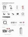
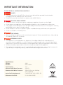
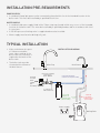
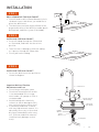
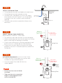
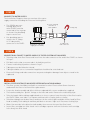
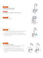
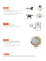
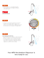
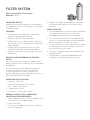
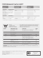
Water Filters Aust
Owners Manual
INSTANT HOT + AMBIENT
FILTERED DISPENSING UNIT
MODEL: K-WFADUOGN
WFA recommends that a qualified tradesperson installs your WFA DUO system.
COMPONENT CHECKLIST
MAIN COMPONENTS
Boiling Tank
Dual Faucet
(with safety lock)
Push Lock Fitting
Locking Clips x 2
DISPENSER FITTING KIT
Rubber Washer
Metal Washer
Locking Nut
Boiler Hose Clamp
Chrome Base Plate
with O-Ring
Threaded Locking Bolt
INSTALLATION KIT
¼" food grade nylon tubing
Pressure Limiting Dual
Check Valve 350kPa
Push Lock fitting ¼" mbsp x ¼"
tube connect & locking clip
FILTER KIT
Filter Head Assembly with mounting
bracket & 2 locking clips
Filter Cartridge
IMPORTANT INFORMATION
Adesso, Futura
PLEASE
READ ALL INSTRUCTIONS CAREFULLY
DANGER
WARNING
SAFETY
• F
IMPORTANT
or continued safety of the WFA Duo, the unit must be installed, operated & maintained in
accordance with the manufacturer's instructions.
• The WFA Duo must be installed in accordance with AS/NZS 3500.4.
Adesso, Futura
DANGER
ELECTRIC SHOCK HAZARD
• To
prevent electric shock, do not place cord, plugs or appliance in water or other liquid.
WARNING
• Do not operate any appliance with a damaged cord, plug, or after the appliance malfunctions.
IMPORTANT
• If the supply cord is damaged, it must be replaced by the manufacturer, its service agent or similarly
qualified persons in order to avoid a hazard.
• Do not attempt to service this product. Repairs should be done by authorized service personnel.
Adesso, Futura
• DDANGER
o not use outdoors or in damp areas.
WARNING
FIRE HAZARD
• W
IMPORTANT
hen installing the appliance, allow a minimum airspace of 100mm around the front, sides, and top
of
the boiler tank for air circulation.
DANGER
Adesso, Futura
PERSONAL INJURY
• T
IMPORTANT
his appliance is not intended for use by persons (including children) with reduced physical,
sensory or mental capabilities, or lack of experience and knowledge, unless they have been given
supervision or instruction concerning use of the appliance by a person responsible for their safety.
WARNING
• Children should be supervised to ensure that they do not play with the appliance.
• T
his appliance is intended for use in household and similar applications, such as light commercial
(up to 8 staff), the hospitality industry, and related residential type environments.
Specifications:
Voltage:
240V
Element:
50Hz 1250W
Tank Capacity:
2.4 L
Minimum Inlet Water Pressure:
240 kPa
Maximum Inlet Water Pressure:350 kPa (Pressure Limiting
Valve supplied)
Australian Safety Approval: Certificate No: ASA-142012-EA
Watermark Certified: Lic No: WM-022455
ASA-142012-EA
INSTALLATION PRE-REQUIREMENTS
POWER SUPPLY
• A standard 10amp 3pin power outlet conveniently placed within 1m of the intended location of the
boiler tank. This must be installed by a qualified electrician.
WATER SUPPLY
• A standard cold water supply fitted with a 15mm stop tap situated within easy access of the intended
location of the boiler tank. This must be installed by a qualified plumber and in accordance with local
& state laws.
• A 350 kPa pressure limiting valve is supplied and must be installed.
• Water supply must be microbiologically safe.
TYPICAL INSTALLATION
• A
llow a minimum air space
of 100mm around the
front, sides, and top of the
boiler tank. No clearance is
required at the back of the
boiler tank.
• T
he boiler tank must be
situated within 600mm of
the dual faucet.
Stop tap
for cold
water
supply
(not
included)
INSTALLATION DIAGRAM
Dual Faucet
Mixer Tap
Pressure Limiting
Dual Check
Valve 350kPa
Filtered Cold water
to dual faucet (blue tube)
¼” mbsp x ¼”
tube connector
Filtered
Water to
boiling tank
(white tube)
Filtered
Hot water
to dual faucet
(clear tube)
Power supply
Boiling Tank
INSTALLATION
STEP 1
Mixer Tap
DRILL 35MM HOLE FOR DUAL FAUCET
• You will need to drill a 35mm diameter hole in
the bench top or sink where you would like to
place the dual faucet.
• T
he dual faucet must be within 600mm of the
proposed location of the WFA Duo under bench
boiling tank, and filter system (if included).
35mm
STEP 2
INSTALLING THE DUAL FAUCET
• Insert all tubing through the 35mm hole
as illustrated, and lower the faucet into
position.
Dual Faucet
• T
ake care not to damage or kink the tubing
as it passes through the 35mm hole.
• Do not pull on the tubing.
STEP 3
INSTALLING THE DUAL FAUCET
• Secure the dual faucet into position as
shown in diagram.
Important Notice of Routine
Maintenance and Care
• Do not keep rotating the spout
• Occasional cleaning of the aerator
is recommended. Use of soapy
water and a soft sponge or cloth is
recommended.
• Avoid cleaning with chemicals,
solvents or harsh detergents (this
may seriously harm surface area)
• If used with hard water or water
with very high mineral content, it is
absolutely necessary to clean and
dry faucet immediately after every
use. (Calcium and other minerals
could seriously damage surface
area).
Dual Faucet
O-Ring
Chrome-plated
Metal Flange
Mounting
Hole 35mm
Rubber
Washer
Metal
Washer
Locking Nut
STEP 4
Dual Faucet
INSTALL THE BOILING TANK
• The boiling tank must be installed below the dual faucet
Maximum distance
between faucet
and boiling tank
= 600mm
• The boiling tank must be mounted vertically.
• T
he boiler tank is designed to sit on the sink cabinet
floor. However there are “keyhole” cut-outs provided
in the back of the unit to allow for wall mounting if
required.
To Filter/Cold
Water supply
Boiling Tank
• T
he boiler tank must be located within 600mm of the
dual faucet.
STEP 5
FAUCET / BOILING TANK CONNECTION
WATER SUPPLY TO BOILER – (white tube)
Water to
boiling tank
(white tube)
Hot water
to dual faucet
(clear tube)
• The end of the white tube must be cut clean and square.
• R
emove red locking clips from the white push-lock fitting
before connecting to the boiling unit and tube.
• F
irmly connect white push lock fitting to boiling unit, pull
back to ensure it is locked and refit red locking clip.
Boiling Tank
• F
irmly insert the white tube into the push-lock fitting,
pull back to ensure it is locked into position, and refit the
locking clip.
STEP 6
HOT WATER FROM BOILER (CLEAR SILICONE TUBE)
• Connect the clear silicon tube to the central outlet
located in the top of the boiling tank.
• S
ecure the large silicon tube with the hose
clamp supplied.
Adesso, Futura
DANGER
Water to
boiling tank
(white tube)
Hot water
to dual faucet
(clear tube)
Boiler
Hose
Clamp
WARNING
IMPORTANT
•Be
sure the hoses are not kinked
or twisted.
•Tubes must be cut to a convenient
length to avoid sagging but must
not be stretched taut.
Boiling Tank
STEP 7
CONNECT TO WATER SUPPLY
The Installation Diagram shows an overview of the water
supply connection including the Pressure Limiting Valve.
Pressure Limiting
Dual Check
Valve 350kPa
• T
he 350kPa pressure
limiting dual check
valve (PLVDC) must be
connected to the stop tap
as shown. Use plumbing
tape to create seal.
• U
se plumbing tape to
connect the ¼" mbsp
to ¼" tube pushfit
connector to the PLVDC
Stop tap for cold water
supply (not included)
Locking clip
¼” mbsp x ¼”
tube connector
STEP 8
CONNECT DUAL FAUCET TO WATER SUPPLY (IF FILTER SYSTEM NOT INCLUDED)
• Take blue tube from Dual Faucet and insert into the tube connector at the end of the PLVDC as shown
in Step 7.
• Pull back on the tube to ensure tube is locked into position.
• Connect red locking clip where shown in Step 7.
• Tubing must not be kinked or twisted.
• Tubing should be cut to a convenient length but should not be stretched taut.
• E
nsure all fittings and tube connections are protected against damage from objects stored in the
cupboard.
STEP 9
INSTALL FILTER SYSTEM (IF INCLUDED) REFER INSTALLATION DIAGRAM
• The filter system should be installed in a convenient location. Please allow 40mm clearance
underneath the filter to facilitate filter replacement.
• Locate the head assembly and affix to kitchen cupboard with screws and bracket supplied.
• The head assembly has 'pushfit' fittings on the inlet and outlet. Remove the red locking clips.
• T
ake the length of blue tubing supplied and cut to size to connect from the outlet of the filter head to
the PLVDC. Make sure tube is cut square and clean with a Stanley knife or similar.
• T
ake blue tubing from the dual faucet and insert in the outlet (right hand side of filter head) of filter
head assembly. Push tubing in and then pull back to ensure a tight seal. Reconnect locking clip.
• Water flow must be in the direction indicated by the arrow on the top of the filter head.
• Insert filter cartridge into filter head - twist cartridge a quarter turn anti clockwise until cartridge
locks firmly into filter head.
STEP 10
COMMISSIONING AND TESTING
• Open cold tap on dual faucet
Adesso, Futura
DANGER
WARNING
IMPORTANT
DO NOT
CONNECT TO POWER SUPPLY AT THIS TIME
STEP 11
• Turn on water supply
Stop tap
(not supplied)
STEP 12
• A
llow water to flow consistently and evenly from the dual faucet
for 1–2 minutes before turning off the cold water tap.
• Check all fittings and tube connections for water leakage.
• If any leaks are noted ensure they are repaired before moving
onto the next step.
STEP 13
FILLING THE BOILING TANK
• Turn the dual faucet hot tap on (Press top of lever down to
release safety lock as shown - then forward).
• T
he tank will begin to fill. There may be a delay of 1 – 2
minutes before water starts to flow from the faucet.
• A
llow water to flow consistently and evenly from the dual
faucet for 2 minutes before turning off the dual faucet hot
water tap.
Pres
and f
Press down
and forward
STEP 14
CHECK FOR LEAKS
• Check all fittings and tube connections to and
from the boiling tank for water leakage.
• If any leaks are noted ensure they are repaired
before moving onto the next step.
STEP 15
Power supply
CONNECT TO POWER SUPPLY
• Plug power lead into power supply and switch on
Pressure
Limiting
Valve
STEP 16
SETTING THE HOT WATER TEMPERATURE
• Turn thermostat dial clockwise to the “MAX”
position as shown.
• T
he Status light should glow red, indicating
that the boiler is heating up.
1/2” fbsp
push lock fitting
Pressure
Limiting
Valve
1/2” fbsp
push lock fitting
Adesso, Futura
DANGER
WARNING
DUO
INSTANT
IMPORTANT
HOT WATER
DO NOT
LEAVE BOILER UNIT UNATTENDED DURING THIS INITIAL HEATING STAGE.
STEP 17
• O
nce the boiler has reached boiling point
steam and hot water will begin venting
out
Press down
of the dual faucet.
and forward
Adesso, Futura
DANGER
SCALDING
DANGER
WARNING
IMPORTANT
STEP 18
• S
lowly turn the thermostat dial anti clock-wise
until the status light changes to green. This
indicates that the boiler has stopped heating and
the hot water has reached the set temperature.
STEP 19
TEST THERMOSTAT SETTING.
• Run the dual faucet hot tap for 1 minute then allow
boiler to re-heat to test the thermostat setting.
DUO
INSTANT
HOT WATER
• If steam and water start to vent from Press
the dual
down
forward to
faucet adjust the thermostat dial backand
slightly
lower the set temperature, and repeat this test
sequence to confirm correct setting.
Your WFA Hot+Ambient Dispenser is
now ready for use.
TROUBLESHOOTING
WATER IS NOT HOT
(assuming cold water supply is connected properly and valve is open)
• Check that the power supply is live.
• Check if the boiling tank is plugged into the power supply and turned on.
• T
urn thermostat control dial fully clockwise. This may produce boiling water in
approximately 15 minutes and possibly be accompanied by a gurgling sound in the tank
and/or water "sputtering" from the dual faucet.
• T
he self re-setting thermal fuse may have tripped. Turn thermostat dial to the “MIN”
position, unplug boiling tank from power supply and allow 1/2 hour to cool before
repeating procedures outlined in Steps 15 onwards.
HOT WATER IS SPURTING OUT OF THE DUAL FAUCET.
• Check all tube connections are correct.
• Repeat hot water temperature setting procedure as outlined in Step 18.
• C
heck that the hose connecting the dual faucet to the boiling tank is not clogged, twisted
or kinked.
WATER FLOW DOES NOT START STRAIGHT AWAY
• A delay of 3 or 5 seconds is normal especially if your WFA Duo has not been used in the
last hour or so. This is due to the efficient operation of the “expansion tank” within the
boiling unit which protects against the risk of hot water dripping from the dispenser.
• Make sure all valves on water supply are open.
• Check the tubes from the dispenser for twisting or kinks.
STEAM APPEARS FROM THE DISPENSER SPOUT.
• Lower temperature setting by turning thermostat dial slightly counter clockwise.
Note: If lowering the thermostat setting does not stop the boiling, unplug the power supply
cord and contact Water Filters Australia on 1300 785 355.
FILTER SYSTEM
WFA Premium Water Filter System
Model No: WFA12
IMPORTANT NOTICE:
Read this performance data sheet and compare
the capabilities of this unit with your actual water
treatment needs.
FEATURES:
• Finely polishes treated water to premium
quality for drinking and cooking.
• Reduces chlorine, taste and odour.
• R
educes dirt, rust, asbestos fibres and other
particulates such as oxidized iron, manganese
and sulphides.
• R
educes parasitic protozoan cysts such as
Giardia, Entamoeba and Cryptosporidium.
• A
bsorbs common earthy, mouldy, fishy tastes
and odours.
HEALTH CLAIM PERFORMANCE CLASSIFIED
BY NSF.
This system has been tested according to NSF/
ANSI 42 and 53 for the reduction of the substances
listed below.
The concentration of the indicated substances
in water entering the system was reduced
to a concentration less than or equal to the
permissable limit for water leaving the system, as
specified in NSF/ANSI 42 and 53.
OPERATING SPECIFICATIONS:
• Capacity: 2,875 litres
• P
ressure Requirement: 10-125 psi
(0.7 - 8.6 bar), non-shock.
• Temperature: 2-38°C
• Flow Rate: 1.9 litres per minute.
GENERAL INSTALLATION / OPERATION/
MAINTENANCE REQUIREMENTS:
• Space required: 34cm x 13cm including 6cm of
clear space for cartridge change.
• Install vertically
• F
lush new cartridge at full flow for 2 minutes
until air is purged.
• Replace
cartridges when capacity is reached,
or when flow becomes too slow, but at least
annually.
SPECIAL NOTICES:
• This drinking water system must be maintained
according to manufacturer’s instructions,
including replacement of filter cartridges.
• D
o not use with water that is microbiologically
unsafe, or of unknown quality without adequate
disinfection before or after the system.
• T
he contaminants or other substances removed
or reduced by the water treatment system are
not necessarily in your water.
• C
heck for compliance with state and local laws
and regulations.
• T
ested under sustained standard laboratory
conditions, actual performance may vary.
PERFORMANCE DATA SHEET
Influent Challenge
Substance
Concentration
Max. Permissible
Product Water
Concentration
Reduction
Requirements
Minimum
Reduction
Average
Requirements
Standard 42
Aesthetic Effects
Chlorine
2.0mg/L±10%
5ppm
≥50%
-
98%
Particulate
at least 10,000
-
≥85%
-
99.8%
Class 1 particles particles/mL
0.5 to<1um
Standard 53
Health Effects
Cyst
Minimum 50,000/L
-
99.95%
99.99%
99.99%
Turbidity
11±1NTU= 0.5NTU1
-
98%
99%
*Tested using flow rate=0.5gpm; pressure=60 psig; pH=7.5 ± 0.5; temp=20oC ± 2.5oC =NTU=Nephelometric Turbidity Units
AS3497
Lic.WM-022045
IAPMO R&T OCEANA
This appliance meets the domestic water treatment
appliance Standards AS/NZS3497 for the following
water treatment processes:
CLASS
TREATMENT TYPE
FUNCTION
PASS
I.
Microbiological Status
Bacteriostatic
Will stop bacteria increasing but will
not stop them unless IIa is passed.
N/A
II.
II (a)
Microbiological Treatment
Bacteria Removal
Will remove or inactivate bacteria.
N/A
II (b)
Virus Removal
Will remove or inactivate virus.
N/A
II (c)
Protozoa Removal
Will remove or inactivate
Cryptosporidium and Giardia.Will not
remove or inactivate bacteria and
virus unless II(a) and II(b) is passed.
3
III.
Turbidity and Particulate
Reduction
Reduces Cloudiness
3
IV.
Taste and Odour Reduction
Reduces Tastes and Odours
3
V.
Chemical Treatment
Decreases Chlorine
3
WARNING: FOR CORRECT OPERATION OF THIS APPLIANCE IT IS ESSENTIAL TO OBSERVE THE
MANUFACTURER’S INSTRUCTIONS.
System tested and Classified against NSF/ANSI Standards 42 and 53 for the reduction of:
Std. No 42 - Aesthic Effects; Chemical Reduction, Chlorine, Taste & Odour, Mechanical
Filtration, Nominal Particulate Class I
Std. No 53 - Health Effects; Chemical Reduction, Lead, Mechanical Filtration,
Cyst, Turbidity
WATER QUALITY
WATER FILTER
ANSI/NSF
STANDARDS 42 and 53
WARRANTY
The unit must only be used for a potable water
source and with cold water (with a temperature
range between 2 and 38°C).
Water Filters Australia Pty Ltd (WFA) warrants
to you, the first person who has purchased and
used the unit (“you”) that this unit is free from
defects due to faulty material and workmanship
in accordance with the conditions set out in this
document.This warranty is provided to you in
addition to your rights at law, including but not
limited to your rights under the Trade Practices
Act 1074 (Cth) and applicable legislation in your
Australian State or Territory.
WHAT THIS WARRANTY COVERS:
This warranty covers defects due to faulty
material and workmanship of the unit supplied
to you:
• F
or a period of 1 year from the date of
purchase in respect of the entire unit,
excluding the Replaceable Elements.The
Replaceable Elements are consumable
components and all parts of the unit which
can be replaced including but not limited
to the filter or water treatment cartridge if
there is a defect in the filter or cartridge.This
does not include the replacement of the filter
or cartridge to extend the life of the filter or
cartridge. The life of the filter cartridge is
affected by water quality, usage and water
pressure.The warranty only extends to the
original purchaser of the unit.
WHAT THIS WARRANTY DOES NOT COVER:
This warranty does not cover the unit or a
Replaceable Element of the unit where:
• T
he defect, fault or failure is attributable, or
substantially attributable to misuse, abuse,
accident, misapplication, neglect, freezing,
oxidizing agents (including but not limited to
chlorine, ozone, chloramines and other related
components) or act of God;
• T
he unit has been in conditions which do
not conform to the recommended design
guidelines or has been operated in a manner
which is contrary to WFA’s printed instructions;
• T
he unit has not been installed in accordance
with WFA’s printed instructions and has
not been installed in compliance with all
applicable laws, regulations and industry
standards;
• T
he unit has not been used in accordance with
the manufacturer’s instructions;
• T
he unit does not meet the conditions for
use described in the Owners Manual or
Performance Data Sheet for this unit
• Y ou use accessories or components which do
not meet WFA’s specifications as set out in the
Owners Manual;
• T
he defect, fault or failure is due to normal
wear and tear;
• T
he defect, fault or failure has occurred where
the unit has been used reasonably or has
reached its serviceable life;
• T
he serial or model number label of the unit is
removed or defaced;
• T
he unit is serviced, modified, altered or
repaired by an unauthorized or unqualified
person.
HOW TO MAKE A CLAIM UNDER THIS
WARRANTY:
To make a claim under this warranty you must
contact WFA within 21days of the defect, fault
or failure occurring. WFA Warranty Contact
number is 1300 785 355. At the time of repair or
replacement under your warranty claim you must
provide to WFA:
• Proof
that you purchased the unit from
an authorized retailer or dealer within the
warranty time; and
• A
copy of a certificate which certifies that
the unit was installed in compliance with
our printed installation instructions and all
applicable laws, regulations and industry
standards. WFA will only pay for repair or
replacement upon receipt of proof of your
purchase showing the date of purchase.
WARRANTY
CONTINUED
Limitation of Liability of WFA under this
warranty: Where a warranty exists or is implied
by law, WFA’s liability is limited (to the extent
that it can be limited) to repair or replacement
of the faulty Replaceable Element or the unit or
an equivalent unit. WFA may, in its discretion,
choose whether it shall repair or replace any unit
or Replaceable Element or WFA may choose to
pay to you the cost of replacing the Replaceable
Element or the unit or the cost of having the unit
repaired. To the extent permitted by law, WFA
assumes no liability whatsoever and disclaims all
liability for direct, indirect or consequential loss,
or special, general or other damage or expense
caused by or arising out of:
• A
ny failure to install or use the unit in
accordance with the Manufacturers
Instructions, the Installation and Owners
Manual or WFA’s printed instructions; or
• T
he purpose for which you are purchasing the
unit.
You acknowledge that the quality of water
supplied and your water usage rate and influent
water pressure may vary seasonally or over a
period of time.
In addition to this water characteristics can
differ if the unit is relocated or the environment
changes.
You acknowledge that WFA does not know your
requirements and cannot and does not warrant
that the unit is fit for the purpose for which you
intend to use the unit or is appropriate for the
purpose for which you intend to use the unit.
WFA does not authorize others to assume any
obligation on its behalf even if you inform them of
the purpose for which you intend to use this unit.
WARNING
WFA does not recommend making alterations
to your existing plumbing to accommodate this
system. If you wish to modify existing plumbing
you must comply with AS 3500 and use a licensed
plumber.
Distributed by Water Filters Australia Pty Limited ABN: 78 089 574 489
Unit 1, 91-93 Old Pittwater Road, Brookvale NSW 2100
PO Box 636 Freshwater NSW 2096
Phone: 61 2 9905 6211
Fax: 61 2 9905 6255
Email: [email protected]
Web: www.wfa.com.au
For all enquiries call the National Customer Service Centre on: 1300 785 355