1
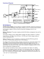
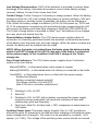
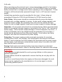
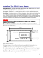
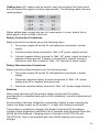
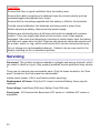
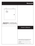
STIII Series POWER SUPPLY Owner's Manual Please read the Installation section of this manual before installing the product. Copyright © Setec Pty Ltd 2013 Disclaimer Setec Pty Ltd makes no claim as to the accuracy or suitability of the information contained in this manual. Setec Pty Ltd accepts no liability for any loss or damage, which may occur as a result of improper or unsafe use of its products. Warranty is only valid if the unit has not been modified by the customer and has not been misused. 2 Contents Introduction..............................................................................................................4 Safety Precautions..............................................................................................4 Accessories.........................................................................................................5 Introduction.........................................................................................................5 Operation............................................................................................................5 Functional Diagram........................................................................................6 STIII Basics........................................................................................................6 Installing The STIII Power Supply...........................................................................9 Wiring Up..........................................................................................................10 Servicing................................................................................................................12 Specifications.........................................................................................................13 Battery Management..............................................................................................14 Frequently Asked Questions..................................................................................15 Anderson Plug Operation.......................................................................................16 Aftersales Service.................................................................................................17 Repairs and Aftersales Service.......................................................................17 Warranty Terms and Conditions........................................................................18 3 Introduction Safety Precautions Please read the Safety Precautions carefully before installing the power supply. Be sure to observe all precautions without fail. After completing installation, conduct a trial operation to check for faults. WARNING Failure to follow these instructions properly may result in personal injury or loss of life. Ensure that there is good ventilation from the battery area. This appliance is not intended for use by young children or infirm persons without supervision. Young children should be supervised to ensure that they do not play with the appliance. Batteries are electrically alive at all times and must be treated with extreme caution. They can supply high short circuit currents, even if they appear damaged. Take care that dropping or touching of metal objects onto the battery cell does not cause short circuits. Remove any personal metal adornment such as a chain, watch or ring, which could cause short circuits and personal injury. CAUTION Failure to observe these instructions properly may result in property damage or personal injury, which may be serious depending on the circumstances. Refer to the installation section before operating. Correct installation is the most critical factor in ensuring the safe use of the power supply. If every consideration of these instructions has been satisfied the power supply will be safe to operate. Ensure that cable connections to batteries have the correct polarity and are protected against accidental short circuit. Ensure that the shrouding supplied with the battery is fitted to the terminals. Before servicing a battery, disconnect the power supply from the mains supply. Do not charge non-rechargeable batteries. Failure to do so may result in the battery catching on fire or possible explosion. Do not allow water or other liquids to enter the installation area. 4 Accessories Accessories provided with this product are: 1. User Manual Introduction These instructions detail the installation and operation requirements for the ST20 III & ST35III power supplies. These have been designed for operation in RV’s providing a DC power system, with optional battery back up. The units operate from 240Vac and provide an isolated 13.65Vdc output at 20A and 35A respectively for powering the load and charging of batteries. All the necessary protection and operating features for the load and batteries are provided. An optional DC input is also provided to enable charging of batteries and powering of the load from an external +13.8V DC power source. The units are fully enclosed ready for direct wall mounting. All connections are at the rear of unit providing convenient wiring and installation. User access to all load and battery fusing has been provided from the front of the unit. Operation Safety: Refer to the installation section before operating. Correct installation is the most critical factor in ensuring the safe use of the power supply. If every consideration of these instructions has been satisfied the power supply will be safe to operate. If the AC supply cord is damaged it must be replaced by the manufacturer, its service agent or similarly qualified persons in order to avoid hazard. The unit is rated to charge a single 12V (up to 6 cells) lead acid battery at 100Ahr Capacity. 5 Functional Diagram DC IN+VE Car Battery 0.8 A Trickle BATERY FUSE BAT +VE Caravan Battery BAT –VE Battery –Ve Vadj LOAD FUSES L1 – L8 8 x Load Outputs –VE AC Input AC / DC 8 x Load Returns LOAD SWITCH Battery Lowvoltage Disconnect Circuit Load Remote disconnect Circuit Remote Load on/off Input Figure 1: Functional Block Diagram STIII Basics AC/DC Power Supply: This provides an isolated 13.65Vdc output for powering of the load and float charging of the battery. Battery current is sensed and monitored by the power supply to ensure that the maximum charging current is not exceeded. Battery Features: The power supply provides full battery management as per the following. The power supply is a four stage battery charger with Boost (VBoost = 14.05V), Float (VFloat = 13.65V), Store (VStore = 13.25V) and Trickle charge modes to ensure long battery life. Battery Charging current is limited to a maximum of 10A (ST20III) and 15A (ST35III). This provides optimum life for the batteries. To charge at the maximum battery charge current above, ensure the load current plus battery current is equal or less than the maximum output current. The charging current will be reduced in situations where the difference between the rated output current and the load current (the available charging current), is less than the maximum charging current. Also note that the battery current sense is provided in the “Batt +ve” battery output. For this feature to work, the load “+ve” and battery “Batt +ve” should not be cross connected. (Appliances should not be connected to both the “Batt +ve” and “+ve” terminals of the power supply. Appliances should be connected to the “+ve” and “ve” load terminals). 6 Low Voltage Disconnection: (LVD) of the batteries is provided to prevent deep discharge of the battery. Automatic reconnection occurs when battery voltage recovers. Battery Current Drain is less than 2mA. Trickle Charge: Trickle Charge to the battery is always present. When the battery voltage is below the LVD (Low voltage disconnect) reconnect voltage (<10V and the mains power or auxiliary power is available, the battery will be charging at 0.8A. When the battery voltage is sufficient (>10.5V for first power up, 11.5V and 11.7V for subsequent reconnection with and without mains respectively) the LVD will connect the battery and allow float charging at 10A/15A (ST20III/ST35III). The Trickle Charge feature is provided to allow “very” flat batteries to be charged at a rate, which will extend their life. Remote Battery Isolate Switch: The STIII series power supplies allow for connection to a remotely positioned switch that provides a manual disconnection of the battery from the loads and the main charger. When the switch contacts are closed, the battery will be isolated from the loads. NOTE: When the battery is isolated from the loads using the battery isolate switch it will NOT charge at the 10/15 A rate even if the mains is connected to the power supply. In this condition it will ONLY charge at the Trickle charge rate. Front Panel Indicators: The STIII series power supplies have 3 indicators visible on the front fascia. Mains(GREEN) – is illuminated when mains power is present. Battery(ORANGE) – is illuminated when the battery is connected to the loads. Fault(RED) – is illuminated when there is a fault with the power supply. Battery fuse Blown1 Battery connected reverse polarity2 Shut down condition (UV and OT)3 Main PCB micro controller malfunction4 Notes 1. Flashing 1s ON, 1s OFF. 2. Solid ON. 3. Flashing 1s ON, 1s OFF, with no battery connected the power supply may be in hiccup mode which will cause the indication to flash with random duty cycle and frequency. 4. Fault Led= Solid On, All other leds = OFF, irrespective of actual mains or LVD status. Auxiliary Power Input: The power supply terminal “Aux In +VE” provides an alternative option for powering of the load and float charging of the batteries when mains voltages are not present. This input is to be powered by a suitable +12V system. (i.e. CAR). The voltage of the auxiliary power source should not exceed 7 14.8 volts. When operating via the external input, current and voltage control for the battery must be provided from the external source. The ST20III/35III does not provide battery current limit or voltage control when operating in this configuration. Trickle Charge is still functional when powered through “Aux In +VE” terminal of power supply. Suitable fuse protection must be provided for this input. A fuse rating not exceeding 20 Amps for ST20III and 30 Amps for ST35III must be used. Solar Power: Solar power should be connected directly across the battery terminals with a voltage regulator in series. A solar panel voltage regulator with maximum output voltage not exceeding 14.8 volts must be used at all times. Failure to use a voltage regulator may result in power supply or battery damage. Generator: 12 volt outputs should not be connected across battery terminal whilst battery is connected to power supply or connected to the “Aux In +VE” terminal of power supply. Serious power supply damage or internal explosion may occur. If a flat 12 volt battery has to be charged using the generators 12 volt output, it should first be disconnected from the power supply. Once battery has being charged it can then be reconnected to power supply. Protection: The power supply provides automatic protection for overload including short circuit, overvoltage, overtemperature and reverse connected battery. In such instances the Fault indicator will illuminate and the power supply will shut down. It will attempt to automatically restart every 5 seconds until such case that the fault is removed. Fusing: Each load circuit and the battery have been fused to provide fault protection and discrimination. Refer to servicing section for maximum fuse ratings. CAUTION: This appliance is not intended for use by young children or infirm persons without supervision. Young children should be supervised to ensure that they do not play with the appliance. In order to avoid hazard when the supply cord becomes damaged, the cord must only be replaced by the manufacturer or its service agent or similar technically qualified person. 8 Installing The STIII Power Supply Host Equipment: The host equipment must ensure that access to the unit (other than the front panel) by the user is prevented. Personnel: Installation is to be carried out only by suitably qualified personnel. Ventilation: Provide a minimum of 80mm clearance above, below and behind the unit. The final enclosure must also provide adequate ventilation to the outside world (or larger internal cavity) to prevent the build up of hot air. Failure to provide adequate ventilation will mean the unit may prematurely trip thermal shutdown. A minimum ventilation of 20,000mm2 to the outside world must be provided. CAUTION Do not install unit in same compartment as batteries or flammable material such as petrol. Ensure that the installation meets the ventilation requirements above. Mechanical and Mounting: 303.5 Four by 4.5 x 9mm Mounting holes at 129.5 (h) x 287 (w) centres 156.5 Fuse Panel Door 1 2 3 4 5 6 7 8 BATT Label Recess x3 LEDS Cut-out for mounting 152 (h) x 272 (w) Depth of unit is 125mm After mounting unit, clip on the front fascia (ensure that all locking clips have engaged) and secure with screw located inside the fuse panel door. DC cables must be sized to carry the maximum full load current and to not exceed the system volt drop requirements. The following cable sizes are recommended. Orientation: The unit is to be installed with the front fascia in a vertical plane. Failure to do this will cause premature temperature shutdown. 9 Wiring Up Mains: This is pre cabled and fitted with AS/NZ mains plug ready for connection to internal GPO. Ensure that the connection to the mains supply is in accordance with the national wiring rules, and that the earth connection is installed. Load, Battery and External DC Input Connections: Connectors are 0.8 x 6.3mm QC tabs. Use mating QC connector suitable for cable size. Connector pin out is shown below. On / off Input F1 F1 F2 F3 F4 F5 Battery Isolate L1+ L1+ L1+ L1+ L2+ LL- Load 11 Load L- Load 2 L- Load 3 L- Load 4 L- Load 5 L3+ F6 F7 L- CAUTION V Ext+ must be supplied from a Fused (F Ext), external voltage. Load 6 L4+ L- Load 7 L5+ F8 LLoad 8 To L- FBATT VBATT+ + Fuse Panel +ve terminals 10 VBATT- _ _ V Ext+ F Ext -ve terminals Plus Vext+ input + To External Voltage Cabling sizes: DC cables must be sized to carry the maximum full load current and not exceed the system volt drop requirements. The following cable sizes are recommended. Where cables pass through any part of a metal panel or cover, ensure that a cable gland or bush is fitted to the hole. Battery Connection Procedures: Battery should be connected as per the following steps. 1. Turn power supply off and all 12 volt equipment connected to power supply. 2. Connect positive battery terminal to “Batt +VE” power supply terminal. 3. Connect negative battery terminal to “Batt VE” power supply terminal or negative chassis ground. If battery is connected to chassis, ensure a connection exist from chassis to “Batt –VE” terminal of power supply. Battery Disconnection Procedures: Battery should be disconnected as per the following steps. 1. Turn power supply off and all 12 volt equipment connected to power supply. 2. Disconnect negative battery terminal connection to “Batt –VE” power supply terminal or negative chassis ground. 3. Disconnect positive battery terminal to “Batt +VE” power supply terminal. Batteries When using batteries with this product always consult with the battery manufacturer for a detailed description of the installation, use and maintenance of the battery. Ensure battery has been charged for several days before a major camping trip (Leave the power supply on for at least 2 – 5 days with battery connected). This product is suitable for charging 12VSealed LeadAcid (SLA) batteries including ValveRegulated LeadAcid (VRLA) batteries both Absorbed Glass Mat (AGM) and Gel batteries. Charging current is limited to 10A (ST20III) and 15A(ST35III). One or two batteries with max.100Ah capacity each can be charged. 11 CAUTION: Ensure that there is good ventilation from the battery area. Ensure that cable connections to batteries have the correct polarity and are protected against accidental short circuit. Ensure that the shrouding supplied with the battery is fitted to the terminals Provide visual notification that batteries are being used in area of use. Before servicing a battery, disconnect the power supply. Batteries are electrically alive at all times and must be treated with extreme caution. They can supply high short circuit currents, even if they appear damaged. Take care that dropping or touching of metal objects onto the battery cell does not cause short circuits. Remove any personal metal adornment such as a chain, watch or ring, which could cause short circuits and personal injury. Do not charge nonrechargeable batteries. Failure to do so may result in the battery catching on fire or possible explosion. Servicing Personnel: This product contains hazardous voltages and energy hazards, which can result in death or injury. Only properly qualified service personnel may service it. There are no internal user serviceable parts. Only the fuses located in the “fuse panel” located on the front panel are serviceable. Isolate mains power, VExt+ and battery before servicing. Replacement of Fuses: Only the DC output Load and Battery fuses may be replaced. Fuse ratings: Load fuses 20A max, Battery Fuse 35A max. Fuse types: 32V Automotive Bussmann ATC series or Littelfuse 257 series or equivalent 12 Specifications Input Voltage: ST20-III & ST35-III: 230 – 240Vac nominal, ±10%, 50/60Hz. The power supply will withstand a 5 minute, +15% surge on the maximum nominal voltage Input Surge: < 40A (cold start) Hold-up Time: > 10mS at full load current and over nominal input voltage operating range Output Current: ST20-III: 20A Continuous (load + battery current) ST35-III: 35A Continuous (load + battery current) Factory Set Voltage 13.65V +/- 0.1V (Vfloat) Load Regulation: < 2% Output Ripple Voltage: < 150mV Over Voltage Protection: < 17V Over Current Protection ST20-III: 20A to 25A (load + battery current) ST35-III: 35A to 38A (load + battery current) Battery Current Limit 10A ± 1A (ST20-III) 15A ± 1A (ST35-III) Battery Connect/ Disconnect Connect: 10.50 ± 0.2V (Input Mains not present) and first power up Connect: 11.70 ± 0.2V (Input Mains not present and not first power up) Connect: 11.50 ± 0.2V (Input Mains present) Disconnect: 10.0 ± 0.2V Battery Trickle Charge 0.8A Battery Drain < 2mA. Efficiency: > 84% Cooling Fan Operation ST35-III Only. Cooling fan on temperature of Transformer: 95C + 3 degrees. Cooling fan off temperature of Transformer: 75C + 3 degrees. Ambient 0OC – 50OC Weight: < 2kg Standards Safety: AS/NZS 60335-1, AS/NZS 60335-2-29 & AS/NZS 61558 EMC CISPR 22 class A Compliance: ERAC+ACMA (RCM) 13 Battery Management To maintain the battery in a good state of health, an intelligently controlled charging algorithm is used. The purpose is to ensure that the correct voltages are applied to the battery terminals at the appropriate times throughout it’s usage cycle. To prevent corrosion on the battery positive plate due to continuous float charging current (VFloat = 13.65V), the unit utilises a storage mode voltage (VStore = 13.25V) when no activity on the battery is detected. This extends the battery life. During store mode, the unit exits to boost mode (VBoost = 14.05V) for 15 minutes every 24hrs to maintain charge in the battery. If battery activity is detected during store mode it exits automatically into float mode. LVD Close (11.5V) VFloat (13.65V) Periodic VBoost (14.05V) VStore (13.25V) 24Hrs 24Hrs 15Mins Trickle Charge (0.8Amps) Time Figure 2: Battery Charging over Time 14 Frequently Asked Questions STIII Can Gel batteries be used with the STIII? Yes. However PLCA are not recommended. Please check recommended battery specifications from your dealer. STIII Can you use a deep cycle battery on the STIII? Yes you can, however the ST 35III is a better option for the charging capabilities and will have a longer life span. STIII Is the STIII a Smart charger? The STIII is a simple "Float" charger, the output (battery) voltage is set to 13.65 V and current limited to 10 A. The STIII is a "4 stage smart charger". STIII Can I add a generator? The type of generator used will impact on how the STIII works. Tests have shown that generators that provide a square wave output have a lower peak voltage and may not provide the voltage required to run the STIII. STIII When the Aux IN+ terminal is used from the tow car, is this a "straight" through connection to the battery? The AUX in provides another source to operate the output loads and charge the battery. It has a diode to ensure only current can enter the ST product through the AUX in. STIII Humming noise when radio is on. I sometime get a humming noise when listening to AM radio. What is it and can anything be done? The STIII does occasionally cause interference (or humming) on the AM band in some installations. The interference occurs when there is no load on the STIII due to pulse skipping, e.g. the battery not connected when plugged into 240 V mains. One suggested way to reduce the pulse skipping is to lightly load the STIII by turning on a light. Physically moving the radio or the STIII (more difficult) can sometimes help reduce or stop the noise. 15 Trailer Plug Operation To wire the STIII to the car follow the diagrams for the different plug types. For more information please contact your dealer. 16 Aftersales Service WARNING: Do not disassemble, modify, or repair the unit. Doing so may result in electric shocks or fire. Repairs and Aftersales Service Consult your Setec dealer. 17 Warranty Terms and Conditions The benefits provided to you under this warranty are in addition to any other rights or remedies you may have, as a consumer, under any other law which applies to Setec Pty Ltd products. Setec Pty Ltd goods come with guaranties that cannot be excluded under the Australian Consumer Law. You are entitled to a replacement or refund for major failure and for compensation for any reasonably foreseeable loss or damage. You are entitled to have the goods repaired or replaced if the goods fail to be of acceptable quality and the failure does not amount to a major failure. Under this warranty Setec Pty Ltd agrees to repair or replace, at our cost, the product purchased by you in Australia if the product does not perform in accordance with the manufacturer's specifications during the period of this warranty. The STIII warranty is valid for a period of one year from the original date of purchase. Please retain your proof of purchase, as this will need to be provided should you wish to claim under this warranty. To be able to claim under this warranty you must (a) Ensure the product is installed by a suitably qualified person and is installed in accordance with this Owner's Manual and any applicable Australian Standard. (b) The product must be operated in accordance with the instructions detailed in this manual. (c) The product must be maintained in accordance with the instructions detailed in this manual. What is excluded from this warranty? Cover for any damage, malfunction or failure resulting from incorrect installation, accidental damage, misuse, abuse, tampering, unauthorised repairs, unauthorised modification by any person, corrosive environment, or infestation by insects or vermin are excluded under this warranty and Setec Pty Ltd accept no liability for the same. How to make a claim under this warranty. (a) Contact Setec Pty Ltd on 03 9213 8400, or your Setec dealer, to obtain return authorisation. (b) Package the product adequately to prevent any further damage, and send the product to location provided when you received your return authorisation. (c) Please include with the product, proof of purchase, a detailed description of the fault, and your contact details. Setec Pty Ltd may seek reimbursement of any costs incurred by them if a product is found to be in good working order. 18 DESIGNED AND MANUFACTURED IN AUSTRALIA 000000 Rev 5A