1
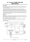
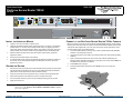
Quick Start Guide
5991-2113
ProCurve Secure Router 7203dl
J8753A
ProCurve 7203dl
Secure Router
J8753A
Power
Fault
Console
Eth 0/2
Slots
1
2
3
Stat
Stat
Stat
Bkp
Bkp
Act
Tx
Tx
Test
Rx
Rx
Eth 0/1
dl
dl
INSTALL THE INTERFACE MODULE
CONNECT TO THE PROCURVE SECURE ROUTER 7203DL CONSOLE
1.
Verify the unit is not connected to a power source.
2.
(Optional) To install the backup module, carefully align the P1 connector on the interface
module with the J1 connector on the backup module. Using only fingertip pressure to
ensure that neither circuit board bends or flexes, firmly seat the connectors. Secure the
backup module to the interface module using the supplied screws and standoff posts.
3.
Slide the interface module into the option slot until the module is firmly positioned
against the chassis.
4.
Secure the screws at both edges of the module.
5.
To install the wide module, align the module with the wide slot and slide the module into
the chassis until it is firmly positioned against the backplane connectors. Secure by
tightening the screws.
GROUND THE ROUTER
1.
Strip one end of the ground wire to the length required for the ring terminal. (Ground wire
and ring terminal are supplied by the user. For more detailed grounding specifications,
please refer to the ProCurve Secure Router Installation Guide.)
2.
Crimp the ground wire to the ring terminal, using a crimp tool of the appropriate size.
3.
Attach the ring terminal to the chassis as shown in the figure to the right.
4.
Connect the other end of the ground wire to a suitable grounding point at your site.
5.
Apply power to the unit.
Note
dl
wide
Before connecting to the ProCurve Secure Router 7203dl Console interface you will need the
following items: VT100 terminal or PC (with VT100 terminal emulation software) and the serial
cable (5184-1894) supplied with your router. (This is the same console cable used in other
ProCurve switches such as the 5300xl series.)
1.
Connect the DB-9 (female) connector of your cable to the DB-9 DTE (male) Console
interface on the front panel of the unit.
2.
Connect the loose end of the cable to the VT100 terminal or PC (with terminal emulation
software).
3.
Open a VT100 terminal session to the ProCurve Secure Router 7203dl using the
following settings: 9600 baud, 8 data bits, no parity bits, and 1 stop bit. Press <Enter> to
activate the HP Command Line Interface.
4.
Enter enable at the > prompt.
5.
Enter the password when prompted or press <Enter> if you have not yet set a
password.
For information on installing the Encryption and Compact Flash modules
please refer to the ProCurve Secure Router Installation Guide included in
your router shipment.
61195890L1-13B, April 2005
www.procurve.com
Copyright 2005 Hewlett-Packard Development Company, LP
Quick Start Guide
5991-2113
ProCurve Secure Router 7203dl
J8753A
CONSOLE PINOUT
ENABLE TELNET ACCESS
The following steps create an IP address (2.2.2.1 /24) for Ethernet port 0/1, an enable password
of enablepw, and a password of secretpw for Telnet access.
1.
Pin
At the (config)# prompt, enter interface eth 0/1 to access the configuration parameters for
the Ethernet port located on the base unit.
2.
Enter ip address 2.2.2.1 /24 to assign an IP address to the Ethernet port using a 24-bit
subnet mask.
3.
Enter no shutdown to activate the interface to pass data.
4.
Enter exit to exit the Ethernet interface commands and return to the Global Configuration
mode.
Name
Description
1
—
Unused
2
RD
Receive Data (input)
3
TD
Transmit Data (output)
4
DTR
Data Terminal Ready (output)
5
SG
6
DSR
Data Set Ready (input)
Signal Ground
5.
Verify that the prompt of your unit displays (config)#.
7
RTS
Request to Send (output)
6.
Enter line telnet 0 4 to change the configuration parameters for the Telnet session.
8
CTS
Clear to Send (input)
7.
Enter login to initiate Telnet access.
9
—
8.
Enter password secretpw to change the login password for the Telnet session.
9.
Enter exit to return to the Global Configuration mode.
Unused
ETHERNET PINOUT
10. Verify that the prompt of your unit displays (config)#.
Pin
Name
12. Enter exit to return to the Enable mode.
1
TX1
Transmit Positive
13. Enter write memory to save the current configuration to memory.
2
TX2
Transmit Negative
3
RX1
Receive Positive
4, 5
—
6
RX2
7, 8
—
11. Enter enable password enablepw to set the Enable Security mode password.
ENABLE WEB GUI ACCESS
To enable Web GUI access, an IP address for an Ethernet port must be assigned. Refer to
Enable Telnet Access above. HTTP and HTTPS are enabled by default but a username and
password must be configured. The example below creates a username of manager and a
password of webpw. Once configured, use a Web browser to access the IP address.
1.
Verify that the prompt of your unit displays (config)#.
2.
Enter username manager password webpw to set the password.
3.
Enter exit to return to the Enable mode.
4.
Enter write memory to save the current configuration to memory.
5.
Open your web browser, and enter the unit’s IP address into the browser address line (e.g.,
http://2.2.2.1).
Note
Description
Unused
Receive Negative
Unused
COMMANDS
Refer to the SROS Command Line Interface Reference Guide (provided on the SROS ProCurve
Documentation CD) for details on configuring the system using the command line interface.
For safety information for the routers and all modules, please refer to the
safety and ESD precautions in the ProCurve Secure Router Installation
Guide included in your router shipment.
61195890L1-13B, April 2005
Printed in the USA
Copyright 2005 Hewlett-Packard Development Company, LP