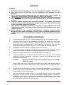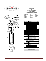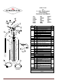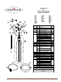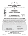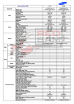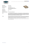
1
When maintenance is indicated, it should be performed by trained
persons having proper equipment. Fire extinguishers are pressure
vessels and must be treated with respect and handled with care.
They are mechanical devices and require periodic maintenance to
be sure that they are ready to operate properly and safely. Amerex
strongly recommends that the maintenance of portable fire
extinguishers be done by a trained professional – your local
authorized Amerex Distributor.
Amerex Corporation makes original factory parts available to insure
proper maintenance – USE OF SUBSTITUTE PARTS RELEASES
AMEREX OF ITS WARRANTY OBLIGATIONS. Amerex parts
have machined surfaces and threads that are manufactured to
exacting tolerances. O-rings, hoses, nozzles, and all metal parts
meet precise specifications and are subjected to multiple in-house
inspections and tests for acceptability. There are substitute parts
available that may be incorrectly labeled as UL component parts,
some are advertised as Amerex type. None of these meet UL
requirements and all of them voids the Amerex extinguisher
warranty and UL listing. DO NOT SUBSTITUTE.
RECHARGE FIRE EXTINGUISHERS IMMEDIATELY AFTER ANY USE
REFERENCES IN THIS MANUAL:
NFPA-10 Portable Fire Extinguishers
AVAILABLE FROM:
National Fire Protection Association
1 Batterymarch Park, P.O, Box 9101
Quincy, MA 02269-9101
CGA C-1 Methods for Hydrostatic Testing of
Compressed Gas Cylinders
CGA C-6 Standard for Visual Inspection of
Compressed Gas Cylinders
Compressed Gas Association, Inc.
4221 Walney Road, 5th Floor
Chantilly, VA 20151-2923
AMEREX CORPORATION – P.O. BOX 81 – TRUSSVILLE, ALABAMA 35173-0081
Phone: 205/655-3271 Fax: 800/654-5980
e-mail: [email protected]
Web Page: http://www.amerex-fire.com
Printed in U.S.A.
0M05602B Rev. 04/09
STORED PRESSURE, HAND PORTABLE
DRY CHEMICAL FIRE EXTINGUISHERS
All fire extinguishers should be installed, inspected and maintained
in accordance with the National Fire Protection Association
standard titled "Portable Fire Extinguishers", NFPA-10 and the
requirements of local authorities having jurisdiction.
ABC (AMMONIUM PHOSPHATE BASE), REGULAR (SODIUM BICARBONATE BASE),
PURPKE K (POTASSIUM BICARBONATE BASE)
OWNERS SERVICE MANUAL
NO. 05602
INSTALLATION, OPERATING & SERVICING INSTRUCTIONS
INSTALLATION
Your layout and particular hazards dictate the placement of fire extinguishers. NFPA-10
requires that hand portable extinguishers with a gross weight less than 40 lbs. be hung with
the top of the extinguisher not more than 5 ft. (1.53 m) above the floor. Extinguishers
having a gross weight greater than 40 lbs. (18.14 kg) should be installed so that the top of
the extinguisher is not more than 3 ½ ft. (1.07m) above the floor. All extinguishers should
be in an accessible location and near an exit. Never install the extinguisher in a
location where a potential hazard would prevent easy access. The operational
temperature range for this extinguisher is -65°F to +120°F (-54°C to +49°C) or -40°F to
+120°F (-40°C to +49°C) [please see the nameplate on your extinguisher]. The
extinguisher should be adequately protected if temperatures outside of this range are
anticipated. Keep the extinguisher clean and free from dirt, ice, chemicals and any
contaminants that may interfere with its proper operation. DO NOT FUNCTIONALLY TEST
THIS FIRE EXTINGUISHER. (Testing or any use may cause the extinguisher to gradually
lose pressure over a period of time and make the extinguisher ineffective.) Never throw an
extinguisher into a fire because rapid heat buildup could cause pressure expansion and
exceed the limitations of the cylinder.
OPERATION
NOTE:
Persons expected to use this extinguisher should be trained in initiating its
operation and in the proper fire fighting technique.
Familiarize all
personnel with this information before an emergency occurs.
1. Remove the extinguisher from wall hanger or bracket.
2. Hold the extinguisher upright, twist and pull the ring (safety) pin, snapping the plastic
lockwire seal.
3. Starting back a minimum of 8 feet from the fire, grasp the nozzle and aim at the base of
the fire nearest you.
4. Keeping the extinguisher upright, squeeze the lever to discharge and sweep the
chemical agent stream from side to side. Work the fire away from you while being alert
for flashbacks. Move closer as the fire is extinguished but not so close as to scatter or
splash the burning material.
5. When the fire is out, stand by and watch for possible re-ignition.
6. Evacuate and ventilate the area immediately after extinguishing the fire. The fumes and
smoke from any fire may be hazardous and can be deadly.
CAUTION:
DISCHARGE TIME AND EFFECTIVE RANGE OF THE AGENT THROW
VARIES ACCORDING TO MODEL – SEE THE SPECIFICATION
LITERATURE FOR YOUR EXTINGUISHER.
RECHARGE FIRE EXTINGUISHERS IMMEDIATELY AFTER ANY USE
1
AMEREX CORPORATION DOES NOT SERVICE, MAINTAIN OR RECHARGE FIRE
EXTINGUISHERS. THIS MANUAL IS PUBLISHED AS A GUIDE TO ASSIST QUALIFIED
SERVICE PERSONNEL IN THE INSPECTION, MAINTENANCE AND RECHARGE OF AMEREX
FIRE EXTINGUISHERS ONLY. NO INSTRUCTION MANUAL CAN ANTICIPATE ALL POSSIBLE
MALFUNCTIONS THAT MAY BE ENCOUNTERED IN THE SERVICE OF FIRE
EXTINGUISHERS. DUE TO THE POSSIBILITY THAT PRIOR SERVICE PERFORMED ON THIS
EQUIPMENT MAY HAVE BEEN IMPROPERLY DONE, IT IS EXTREMELY IMPORTANT THAT
ALL WARNINGS, CAUTIONS AND NOTES IN THIS MANUAL BE CAREFULLY OBSERVED.
FAILURE TO HEED THESE INSTRUCTIONS COULD RESULT IN SERIOUS INJURY.
AMEREX ASSUMES NO LIABILITY FOR SERVICE, MAINTENANCE OR RECHARGE OF FIRE
EXTINGUISHERS BY PUBLISHING THIS MANUAL.
INSPECTING THE EXTINGUISHER
This extinguisher should be inspected at regular intervals (monthly or more often if
circumstances dictate) to insure that it is ready for use. Inspection is a "quick check"
that a fire extinguisher is available and is in operating condition. It is intended to give
reasonable assurance that the fire extinguisher is fully charged. This is done by
verifying that it is in its designated place, that it has not been actuated or tampered
with, and that there is no obvious physical damage or condition to prevent its operation.
PERIODIC INSPECTION PROCEDURES
(Monthly or more often if circumstances dictate)
[NFPA-10] Periodic inspection of fire extinguishers shall include a check of at least the
following items:
1.
2.
3.
4.
5.
6.
Location in designated place.
No obstruction to access or visibility.
Pressure gauge reading or indicator in the operable range or position.
Operating instructions on nameplate and facing outward.
Safety seals and tamper indicators not broken or missing.
Examination for obvious physical damage, corrosion, leakage, or clogged nozzle.
MAINTENANCE
[NFPA-10]
At least once a year or more frequently if circumstances require,
maintenance should be performed. Maintenance is a "thorough check" of the
extinguisher. It is intended to give maximum assurance that a fire extinguisher will
operate effectively and safely. It includes a thorough examination for physical damage
or condition to prevent its operation and any necessary repair or replacement. It will
normally reveal if hydrostatic testing or internal maintenance is required.
2
MAINTENANCE – SERVICE PROCEDURE
WARNING:
1.
BEFORE SERVICING BE SURE THE EXTINGUISHER AGENT CYLINDER IS NOT
PRESSURIZED.
THIS PROCEDURE IS BEST ACCOMPLISHED WITH THE
EXTINGUISHER IN AN UPRIGHT POSITION AND ON A LEVEL SURFACE.
Clean extinguisher to remove dirt, grease or foreign material. Check to make sure that the
instruction nameplate is securely attached and legible. Inspect the cylinders for corrosion,
abrasion, dents or weld damage. If any damage is found, hydrostatically test in accordance with
instructions in CGA C-1 and C-6 and NFPA 10.
Note: When cleaning, avoid use of solvents around the pressure gauge. They
could seriously damage the plastic gauge face.
2.
Inspect the extinguisher for damaged, missing or substitute parts.
parts are approved for use on Amerex fire extinguishers.
Only factory replacement
3.
Weigh the extinguisher and compare with weight printed in the "Maintenance" section on the
nameplate (label). Recharge extinguisher if weight is not within indicated allowable tolerances.
4.
Check the date of manufacture printed on the extinguisher label (nameplate) or on the agent
cylinder dome. The agent cylinder must be hydrostatically tested every 12 years to the test
pressure indicated on the nameplate.
5.
Visually inspect the pressure gauge:
a. If bent, damaged or improper gauge, depressurize and replace.
b. If pressure is low, check for leaks.
c. If over pressurized (overcharged), depressurize the extinguisher and follow recharge
instructions.
6.
Check ring pin for freedom of movement. Replace if bent or if removal appears difficult.
7.
Inspect discharge lever for any dirt or corrosion which might impair freedom of movement.
Inspect carrying handle for proper installation. If lever, handle or rivets are damaged replace
with proper Amerex part(s).
8.
Install new tamper seal if broken and record service data on the extinguisher inspection tag.
9.
Remove nozzle or hose and horn assembly and visually inspect inside valve body. (Chemical in
the valve body may indicate that the extinguisher has been partially discharged and should
therefore be recharged). Inspect nozzle or the hose & horn assembly for damage – replace as
necessary. Blow air through nozzle or hose and horn to insure passage is clear of foreign
material.
10.
Inspect the valve assembly for corrosion or damage to hose thread connection. Replace valve
assembly or component parts as necessary following the proper depressurization and recharge
procedures. If valve removal is necessary, complete all steps in the Recharge Procedure.
11.
Install nozzle or hose and horn assembly.
12.
Replace the extinguisher on the wall hanger or in the vehicle bracket making sure that it fits the
bracket properly and the bracket is securely attached – replace the bracket if necessary.
3
COMPLETE MAINTENANCE – SIX YEAR TEARDOWN
[NFPA-10] Every six years, stored pressure extinguishers that require a 12 year hydrostatic test
shall be emptied and subjected to the applicable maintenance procedures. When the applicable
maintenance procedures are performed during periodic recharging or hydrostatic testing, the
six year requirement shall begin from that date.
NOTE: Some states have legislation which requires "Complete Maintenance" on an
annual basis. Please contact your local Amerex Distributor to see if these requirements
apply to you.
1. Discharge chemical and pressure into a "closed" dry chemical recovery system (several are
commercially available). Make sure that the extinguisher is completely empty and depressurized.
NOTE:
A "closed recovery system" is designed to prevent loss of the chemical "fines".
Loss of the "fines" could result in reduced extinguisher efficiency.
2. Clean extinguisher to remove dirt, grease or foreign material.
Check to make sure that the
instruction nameplate is securely fastened and legible. Inspect the cylinder for corrosion, abrasion,
dents or weld damage. If any of these conditions are found and you doubt the integrity of the
cylinder, hydrostatically test to factory test pressure marked on the nameplate (label), using the
proof pressure method, in accordance with CGA C-1 and NFPA 10.
NOTE:
When cleaning, avoid use of solvents around the pressure gauge. They could
seriously damage the plastic gauge face.
3. Inspect the extinguisher for damaged, missing or substitute parts.
ONLY FACTORY
REPLAEMENT PARTS ARE APPROVED FOR USE ON AMEREX FIRE EXTINGUISHERS.
4. Check the date of manufacture on the extinguisher label (nameplate).
Cylinder must be
hydrostatically (proof pressure) tested every 12 years to the test pressure indicated on the
nameplate.
5. Visually inspect the pressure gauge – if bent, damaged or improper type or pressure – replace with
the proper Amerex pressure gauge (see Parts List).
6. Check ring pin for freedom of movement. Replace if bent or if removal appears difficult.
7. Inspect discharge lever for any dirt or corrosion which might impair freedom of movement. Inspect
carrying handle for proper installation. If lever, handle or rivets are damaged, replace with proper
Amerex parts.
8. Remove nozzle or hose and horn assembly and visually inspect threads on nozzle or house
coupling, horn and hose for damage, and replace as necessary. Blow air through nozzle or hose
and horn to insure passage is clear of foreign material.
9. Inspect the valve assembly for corrosion or damage to nozzle or hose thread connection. Replace
valve assembly or component parts as necessary.
WARNING:
Before attempting to disassemble the extinguisher be sure it is completely
depressurized.
10. Remove and disassemble valve assembly by removing downtube, spring and valve stem
assembly. Remove collar o-ring from valve.
11. Complete steps 3 through 14 of Recharge Procedure.
4
RECHARGE
WARNING:
a. Before attempting to disassemble, be sure the extinguisher is completely depressurized.
b. Never have any part of your body over the extinguisher while removing the valve
assembly.
c. Use a protective shield between you and the pressure gauge while charging an
extinguisher. Do not stand in front of the gauge if a shield is not available.
d. Use a regulated pressurizing source of dry nitrogen only with a minimum dew point of
minus 70ºF (minus 57C). Set the regulator to no more than 25 psi above the operating
pressure.
e. Check and calibrate regulator gauge at frequent intervals. The regulator gauge should
be used to determine when the intended charging pressure has been reached. Do not
use the extinguisher gauge for this purpose.
f. Never leave an extinguisher connected to a regulator of a high pressure source for an
extended period of time. A defective regulator could cause the cylinder to rupture due to
excessive pressure.
g. Do not mix types of dry chemicals in extinguishers, recharge or recovery systems.
Mixing ABC (acidic base) with Regular, Purple-K, Super-K or Monnex (alkaline base) dry
chemicals may result in a chemical reaction capable of developing a dangerous pressure
buildup.
RECHARGING PROCEDURE
1.
Perform steps 1 through 10 of the "Complete Maintenance (Six Year Teardown)" section.
2.
Thoroughly clean all parts of the disassembled valve with a soft bristle brush or soft cloth.
Blow the valve out with air or nitrogen. Inspect the collar o-ring, valve stem, spring and
downtube assembly, and replace parts if worn or damaged. Lubricate the collar o-ring and
small o-ring on the valve stem with Visilox V-711 (do not lubricate the valve stem seal).
3.
Reassemble the valve assembly, including downtube and set aside.
4.
Remove any chemical remaining in the cylinder and check the condition. Properly dispose
of any chemical that is contaminated or caked in accordance with local regulations.
5.
Inspect the cylinder interior following CGA Visual Inspection Standard C-6.
6.
Using an accurate scale, fill cylinder with the correct amount and type of dry chemical
specified on the label (nameplate). Use Amerex chemical which has been kept free of
moisture and contamination.
CAUTION:
Filling by eye alone could cause potentially dangerous overfilling –
always use a scale.
7.
Clean cylinder collar o-ring seat and collar threads with a small brush and then wipe off
surfaces with a clean cloth to remove dust. Lightly brush the collar o-ring seat with Visilox
V-711.
8.
Carefully center the downtube and install valve assembly hand tight to the cylinder (the
bottom of the valve body should touch the top of the cylinder collar). Attach the nitrogen
charging adapter to the valve assembly.
9.
With the extinguisher properly secured in an upright position,
pressurizing line with a quick connect to the nitrogen charging
extinguisher operating lever and pressurize extinguisher with dry
operating pressure. When the desired pressure has been reached,
off nitrogen supply and remove the quick connect.
connect your nitrogen
adapter. Depress the
nitrogen to the proper
release the lever. Shut
5
10.
11.
Check extinguisher for leaks by applying detecting fluid or a solution of soapy water to the
nitrogen charging adapter orifice, around the collar o-ring sealing area, cylinder welds and
gauge. Remove the nitrogen charging adapter. Blow air or nitrogen into the interior of the
valve assembly to remove any remaining leak detecting fluid. Wipe exterior of extinguisher
to remove any remaining residue.
Install nozzle or hose and horn assembly.
12.
Install ring pin with ring facing the front of the extinguisher.
13.
Install tamper seal. Record recharge date and attach new recharge tag.
14.
Weigh assembled extinguisher and confirm that the total weight is within the allowable
tolerances indicated in the Maintenance section of the nameplate (label).
TROUBLESHOOTING GUIDE
WARNING: Determine the source of a leak before the extinguisher is depressurized. The
extinguisher must be completely depressurized before any attempt is made to devalve it and
correct a leakage problem. To depressurize – hold the extinguisher in an inverted position and
slowly squeeze the discharge handle. Some chemical remaining in the downtube will be
expelled so care should be taken in the area being used for depressurizing. Thoroughly clean
all valve parts after depressurization and valve removal.
PROBLEM
CORRECTIVE ACTION
1.
Leak at collar o-ring
Remove valve assembly, remove and
discard o-ring, clean collar and lube lightly
with Visilox V-711. Clean o-ring groove on
valve and install new collar o-ring. Lubricate
with Visilox V-711.
2.
Leak through valve
Check valve stem seating area for scratches
or foreign matter. Clean seating area with a
tooth brush and soft cloth. Install new valve
stem assembly.
3.
Leak around gauge
Remove gauge*, clean threads and reinstall
using Teflon tape on the gauge threads.
4.
Defective gauge
Remove defective gauge* an install the
proper Amerex pressure gauge using Teflon
tape on the gauge threads.
5.
Leak in the cylinder
Contact Amerex if under warranty,
otherwise mark "REJECTED" and remove
from service or return to owner.
* Pressure gauge threads are coated with a special epoxy at the
factory. For easy removal, soak the valve assembly in hot water
(180°F) for two to four minutes. Remove gauge with a thin 7/16"
open end wrench.
6
PARTS LIST
for
1 – 6 lb. Dry Chemical
(Fixed Nozzle)
Aluminum Valve Models
A/B/C403
409
A/B409
A/B410
Item
No.
1
1A
2
3
3A
4
5
5A
5B
6
7
7A
7B
Part
No.
12699
11823
14220
12494
01926
03741
03211
01276
01253
03353
01412
16353
00532
01387
11825
01060
06067
02625
08184
03103
11826
01064
09001
09002
416
A/B416
417
A/B417
425
A/B459
A620
Description
Valve Assembly – A620
ALL OTHER MODELS
Hanger Loop w/Screw (Optional)
Nozzle-A620T (.076 Short)
417,A/B417 (.129)
Std.
Pkg.
1
1
6
409,416T,A/B409,A/B416 (.173P)
403,A/B403 (.120ST)
410,A/B410 (.120)
425 (.166)
459 (.144)
Ring Pin
Ring Pin 1 lb. & 2 ½ lb.
Chain (Nylon) for Ring Pin
Lockwire Seal (Yellow)
Lever & Rivet "A/B" Valve
Rivet Only for Lever Old & A/B Vlv
Lever & Rivet – A620
Lever & Rivet – Forged Valve
Gauge – 100 psi for A620
Gauge – 195 psi
Handle & Rivet "A/B" Valve
Rivet Only for Handle – All Valves
Handle & Rivet – A620
Handle & Rivet–2 ½ & 5 lb – Forged
Valve
Handle & Rivet – 6 lb. Forged Vlv
Collar O-Ring
Collar O-Ring – Bulk Bag
06092
Valve Stem Assembly
Valve Stem Assembly – Bulk Bag
05235
Valve Stem O-Ring
01074
Spring
06069
Downtube/Retainer Asy – A620
417, C403, 403, 410, A417,
01075
A403,A410
409, 425, 416, A/B409, B403,
06212
B410, B417, A/B416
03397
459
ALL BRACKETS – SEE BRACKET PAGE
09003
05241
8
9
10
11
12
6
24
24
24
500
1
24
1
1
6
6
1
24
1
1
1
24
100
6
96
24
6
1
ALL FILL & HYDROTEST ADAPTERS – SEE ADAPTER PAGE
ALL VALVE ASSEMBLIES INCLUDE VALVE BODY,
GAUGE, LEVER & HANDLE
7
PARTS LIST
for
5 - 20 lb. Dry Chemical
(Hose & Horn)
Aluminum Valve Models
400
A400
A/B402
A411
A412
A413
Item
No.
1
1A
2
3
4
4A
5
6
6A
6B
7
8
8A
8B
9
10
11
12
13
14
15
(optional)
443
A/B443
453
A/B453
456
B456
A/B457
479
A/B479
500
A/B500
Part
No.
11823
11824
14220
07641
14849
06215
05248
05564
11221
11223
01532
06978
01412
00532
01387
Description
Valve Assembly – 5, 5½, 6 & 10 Lb
20 Lb.
Hanger Loop w/Screw (Optional)
Hose & Horn Asy-400, A400 (.149)
A/B402 (.157)
453, A/B453, A/B500 (.147)
479, 500, 443, A/B479,A/B443 (.152)
456, A/B456, A/B457 (.191)
A411 (.209)
A412, A413 (.177)
Hose Gasket (O-Ring) - All 5,6, & 10 Lb.
A411, A412, A413
Ring Pin
Chain (Nylon) for Ring Pin
Lockwire Seal (Yellow)
Lever & Rivet-A400,A/B402,A/B453
11825
A/B479, A/B500, A/B443, A/B456,
A/B457, A411, A412, A413
01060
Rivet Only for Lever – Old & "A" Valve
02625
Lever & Rivet – 400,453,479,443,456
03103
Gauge – 195 psi
Handle & Rivet-400,A/B402,A/B453
11826
A/B479, A/B500, A/B443, A/B456,
A/B457
12405
A411, A412, A413
01064
Rivet Only for Handle - All 5-10 lb.
12201
A411, A412, A413
09002
Handle & Rivet – 453, 479, 500
09003
400, 443, 456
05241
Collar O-Ring
Collar O-Ring – Bulk Bag
06092
Valve Stem Assembly
Valve Stem Assembly – Bulk Bag
05235
Valve Stem O-Ring
01074
Spring
Downtube/Retainer Assembly - 456,
01519
A/B456, A/B457
11674
A411, A412, A413
A/B402, 453, 479, 500, A/B453, A/B479,
06212
A/B500
03397
400, 443, A400, A/B443
Strap & Clip Asy (Black Plastic-3/8" Hose)
15747
All 5-10 lb.
Strap & Clip Asy (Black Plastic-1/2" Hose)
14778
All 20 lb.
12383
Protective Ring for Bottom of Cylinder-7"
ALL BRACKETS – SEE BRACKET PAGE
Std.
Pkg.
1
1
6
6
24
24
24
24
500
1
24
1
6
1
24
1
24
100
6
96
24
6
1
1
1
ALL FILL & HYDROTEST ADAPTERS – SEE ADAPTER PAGE
ALL VALVE ASSEMBLIES INCLUDE VALVE BODY, GAUGE, LEVER & HANDLE
P/N 05248 & P/N 06215 Hose & Horn Asy are both Valid for use on
Model 500
8
PARTS LIST
for
5-30 lb. Dry Chemical
Brass Valve Models
408
415
419
423
424
B424
Item
No.
1
1A
1B
2
3
4
5
5A
6
7
8
8A
9
9A
10
11
12
13
14
15
B441
447
B447
460
B460
Part
No.
461
B461
462
B462
692
693
Description
Valve Assembly – All models
Hanger Loop w/Screw – "B"
Models B441,B447,B460 – 10 lb.
Hanger Loop w/Screw –
16694
5 lb., 6 lb., & 20 lb.
05240
Collar O-Ring
Collar O-Ring – Bulk Bag
03753
Hose & Horn Asy–424, B424 (.140)
01178
441, 447-B447 (.173)
03753
61-B461, 462-B461 (.140)
06095
419, 460-B460, B441 (.152)
03339
423 (.174)
05174
415 (.177)
03332
408 (.173)
12603
692 (.216)
13439
693 (.191)
06978
Hose Gasket (O-Ring)
00160
Ring Pin, Stainless Steel
00532
Chain (Nylon) for Ring Pin
01387
Lockwire Seal (Yellow)
Strap & Hose Clip Asy (Black
15747
Plastic) 3/8" All 4½ & 5" Dia
Cylinders
Strap & Hose Clip Asy (Black
14778
Plastic) ½" All 7" Dia Cylinders
Strap & Hose Clip Asy (Black
14871
Plastic) ½" All 8" Dia Cylinders
07762
Lever & Rivet – All Models
01563
Rivet Only for Lever
09020
Handle & Rivets – All Models
01564
Rivets Only for Handle (2 Req'd)
03965
Gauge – 195 PSI
05243
Valve Stem O-Ring
06093
Valve Stem Assembly
Valve Stem Assembly – Bulk Bag
00383
Spring
01696
D'tube/Retainer Asy-424-B424
01700
419
03754
461-B461, 462-B462
02609
441-B441, 447-B447, 460-B460
01667
408, 415, 423
09583
692, 693
Protective Ring for Bottom of Cyl 7"
12383
Protective Ring for Bottom of Cyl 7"
12952
ALL BRACKETS – SEE BRACKET PAGE
Std.
Pkg.
11952
1
15363
1
24
100
1
1
1
1
24
24
24
500
1
1
24
1
24
6
24
6
96
6
1
1
1
ALL FILL & HYDROTEST ADAPTERS – SEE ADAPTER PAGE
ALL VALVE ASSEMBLIES INCLUDE VALVE BODY, GAUGE, LEVER &
HANDLE
P/N 05248 & P/N 06215 Hose & Horn Asy are both Valid for use on
Models 500 & 500T
(optional)
9