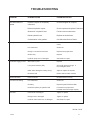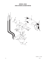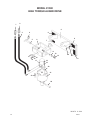
1
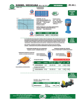
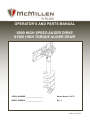
OPERATOR’S AND PARTS MANUAL
X900 HIGH SPEED AUGER DRIVE
X1500 HIGH TORQUE AUGER DRIVE
SERIAL NUMBER: ___________________
Manual Number: 24772
MODEL NUMBER: ___________________
Rev. 3
800-456-7100 I www.paladinattachments.com
503 Gay Street, Delhi, IA 52223, United States of America Copyright ©
M-817 6-10-14-5
TABLE OF CONTENTS
AUGER DRIVES
PREFACE...........................................................................................................................................................3
SAFETY PRECAUTIONS
SAFETY STATEMENTS............................................................................................................................ 5
GENERAL SAFETY PRECAUTIONS.....................................................................................................5-7
EQUIPMENT SAFETY PRECAUTIONS................................................................................................8-9
INSTALLATION & OPERATION
INSTALLING THE DRIVE UNIT.............................................................................................................. 10
INSTALLING AN AUGER................................................................................................................... 10-11
OPERATION....................................................................................................................................... 11-12
STORAGE...............................................................................................................................................13
LIFT POINTS...........................................................................................................................................13
TIE DOWN POINTS................................................................................................................................ 14
TRANSPORTING.................................................................................................................................... 14
MAINTENANCE
SERVICE INTERVALS............................................................................................................................ 15
PLANETARY CAPACITIES..................................................................................................................... 15
CHECKING PLANETARY GEAR CASE OIL........................................................................................... 15
CHANGING PLANETARY GEAR CASE OIL.......................................................................................... 15
WEAR PARTS......................................................................................................................................... 16
TROUBLESHOOTING.................................................................................................................................. 17
LIMITED WARRANTY.................................................................................................................................. 19
PARTS
X900 HIGH SPEED AUGER DRIVE..................................................................................................20-21
X1500 HIGH TORQUE AUGER DRIVE.............................................................................................22-23
M-2248
24772
6-11-14-2
1
THIS PAGE
IS INTENTIONALLY
BLANK
2
24772
PREFACE
GENERAL COMMENTS
Congratulations on the purchase of your new attachment! This product was carefully designed and manufactured to give you many years of dependable service. Only minor maintenance
(such as cleaning and lubricating) is required to keep it in top working condition. Be sure to observe all maintenance procedures and safety precautions in this manual and on any safety decals
located on the product and on any equipment on which the attachment is mounted.
This manual has been designed to help you do a better, safer job. Read this manual carefully and become familiar with its contents.
WARNING! Never let anyone operate this unit without reading the "Safety Precautions"
and "Operating Instructions" sections of this manual.
Always choose hard, level ground to park the vehicle on and set the brake
so the unit cannot roll.
Unless noted otherwise, right and left sides are determined from the operator’s control position when facing the attachment.
NOTE: The illustrations and data used in this manual were current (according to the information available to us) at the time of printing, however, we reserve the right to redesign and
change the attachment as may be necessary without notification.
BEFORE OPERATION
The primary responsibility for safety with this equipment falls to the operator. Make sure the
equipment is operated only by trained individuals that have read and understand this manual. If
there is any portion of this manual or function you do not understand, contact your local authorized
dealer or the manufacturer to obtain further assistance. Keep this manual available for reference.
Provide the manual to any new owners and/or operators.
SAFETY ALERT SYMBOL
This is the “Safety Alert Symbol” used by this industry. This symbol is used to warn
of possible injury. Be sure to read all warnings carefully. They are included for your
safety and for the safety of others working with you.
SERVICE
Use only manufacturer replacement parts. Substitute parts may not meet the required standards.
Record the model and serial number of your unit on the cover of this manual. The parts
department needs this information to insure that you receive the correct parts.
SOUND AND VIBRATION
Sound pressure levels and vibration data for this attachment are influenced by many different parameters: some items are listed below (not inclusive):
• prime mover type, age, condition, with or without cab enclosure and configuration
• operator training, behavior, stress level
• job site organization, working material condition, environment
Based on the uncertainty of the prime mover, operator, and job site, it is not possible to get precise machine and operator sound pressure levels or vibration levels for this attachment.
NOTE: A list of all Paladin Patents can be found at http//www.paladinattachments.com/patents.asp.
M-934
24772
10-22-13-5
3
THIS PAGE
IS INTENTIONALLY
BLANK
4
24772
SAFETY STATEMENTS
THIS SYMBOL BY ITSELF OR WITH A WARNING WORD THROUGHOUT THIS MANUAL IS USED TO CALL YOUR ATTENTION TO INSTRUCTIONS INVOLVING YOUR
PERSONAL SAFETY OR THE SAFETY OF OTHERS. FAILURE TO FOLLOW THESE
INSTRUCTIONS CAN RESULT IN INJURY OR DEATH.
DANGER
THIS SIGNAL WORD IS USED WHERE SERIOUS INJURY OR DEATH
WILL RESULT IF THE INSTRUCTIONS ARE NOT FOLLOWED PROPERLY.
WARNING
THIS SIGNAL WORD IS USED WHERE SERIOUS INJURY OR DEATH
COULD RESULT IF THE INSTRUCTIONS ARE NOT FOLLOWED PROPERLY.
CAUTION
. HIS SIGNAL WORD IS USED WHERE MINOR INJURY COULD RESULT IF
T
THE INSTRUCTIONS ARE NOT FOLLOWED PROPERLY.
NOTICE
NOTICE INDICATES A PROPERTY DAMAGE MESSAGE.
GENERAL SAFETY PRECAUTIONS
WARNING! READ MANUAL PRIOR TO INSTALLATION
Improper installation, operation, or maintenance of this equipment could result in serious injury or death. Operators and maintenance personnel should read this manual,
as well as all manuals related to this equipment and the prime mover thoroughly
before beginning installation, operation, or maintenance. FOLLOW ALL SAFETY
INSTRUCTIONS IN THIS MANUAL AND THE PRIME MOVER’S MANUAL(S).
READ AND UNDERSTAND ALL SAFETY STATEMENTS
Read all safety decals and safety statements in all manuals prior to operating or
working on this equipment. Know and obey all OSHA regulations, local laws, and
other professional guidelines for your operation. Know and follow good work practices when assembling, maintaining, repairing, mounting, removing, or operating this
equipment.
KNOW YOUR EQUIPMENT
Know your equipment’s capabilities, dimensions, and operations before operating.
Visually inspect your equipment before you start, and never operate equipment that
is not in proper working order with all safety devices intact. Check all hardware to
ensure it is tight. Make certain that all locking pins, latches, and connection devices
are properly installed and secured. Remove and replace any damaged, fatigued, or
excessively worn parts. Make certain all safety decals are in place and are legible.
Keep decals clean, and replace them if they become worn or hard to read.
24772
M-806
7-28-05-2
5
GENERAL SAFETY PRECAUTIONS
WARNING! PROTECT AGAINST FLYING DEBRIS
Always wear proper safety glasses, goggles, or a face shield when driving pins in or
out, or when any operation causes dust, flying debris, or any other hazardous material.
WARNING! LOWER OR SUPPORT RAISED EQUIPMENT
Do not work under raised booms without supporting them. Do not use support material made of concrete blocks, logs, buckets, barrels, or any other material that could
suddenly collapse or shift positions. Make sure support material is solid, not decayed, warped, twisted, or tapered. Lower booms to ground level or on blocks. Lower
booms and attachments to the ground before leaving the cab or operator’s station.
WARNING! USE CARE WITH HYDRAULIC FLUID PRESSURE
Hydraulic fluid under pressure can penetrate the skin and cause serious injury or
death. Hydraulic leaks under pressure may not be visible. Before connecting or disconnecting hydraulic hoses, read your prime mover’s operator’s manual for detailed
instructions on connecting and disconnecting hydraulic hoses or fittings.
• Keep unprotected body parts, such as face, eyes, and arms as far away as
possible from a suspected leak. Flesh injected with hydraulic fluid may develop
gangrene or other permanent disabilities.
• If injured by injected fluid, see a doctor at once. If your doctor is not familiar with
this type of injury, ask him or her to research it immediately to determine proper
treatment.
• Wear safety glasses, protective clothing, and use a piece of cardboard or wood
when searching for hydraulic leaks. DO NOT USE YOUR HANDS! SEE ILLUSTRATION.
CARDBOARD
HYDRAULIC HOSE
OR FITTING
MAGNIFYING GLASS
6
M-807 7-28-05-2
24772
GENERAL SAFETY PRECAUTIONS
WARNING! DO NOT MODIFY MACHINE OR ATTACHMENTS
Modifications may weaken the integrity of the attachment and may impair the function, safety, life, and performance of the attachment. When making repairs, use only
the manufacturer’s genuine parts, following authorized instructions. Other parts may
be substandard in fit and quality. Never modify any ROPS (Roll Over Protection
Structure) or FOPS (Falling Object Protective Structure) equipment or device. Any
modifications must be authorized in writing by the manufacturer.
WARNING! SAFELY MAINTAIN AND REPAIR EQUIPMENT
• Do not wear loose clothing or any accessories that can catch in moving parts. If
you have long hair, cover or secure it so that it does not become entangled in the
equipment.
• Work on a level surface in a well-lit area.
• Use properly grounded electrical outlets and tools.
• Use the correct tools for the job at hand. Make sure they are in good condition for
the task required.
• Wear the protective equipment specified by the tool manufacturer.
SAFELY OPERATE EQUIPMENT
Do not operate equipment until you are completely trained by a qualified operator
in how to use the controls, know its capabilities, dimensions, and all safety requirements. See your machine’s manual for these instructions.
• Keep all step plates, grab bars, pedals, and controls free of dirt, grease, debris,
and oil.
• Never allow anyone to be around the equipment when it is operating.
• Do not allow riders on the attachment or the prime mover.
• Do not operate the equipment from anywhere other than the correct operator’s
position.
• Never leave equipment unattended with the engine running, or with this attachment in a raised position.
• Do not alter or remove any safety feature from the prime mover or this attachment.
• Know your work site safety rules as well as traffic rules and flow. When in doubt
on any safety issue, contact your supervisor or safety coordinator for an explanation.
24772
M-808 7-28-05-2
7
EQUIPMENT SAFETY PRECAUTIONS
WARNING! KNOW WHERE UTILITIES ARE
Observe overhead electrical and other utility lines. Be sure equipment will clear
them. When digging, call your local utilities for location of buried utility lines, gas,
water, and sewer, as well as any other hazard you may encounter.
WARNING! EXPOSURE TO RESPIRABLE CRYSTALLINE SILICA DUST
ALONG WITH OTHER HAZARDOUS DUSTS MAY CAUSE SERIOUS OR FATAL RESPIRATORY DISEASE.
It is recommended to use dust suppression, dust collection and if necessary personal
protective equipment during the operation of any attachment that may cause high
levels of dust.
WARNING! REMOVE PAINT BEFORE WELDING OR HEATING
Hazardous fumes/dust can be generated when paint is heated by welding, soldering
or using a torch. Do all work outside or in a well ventilated area and dispose of paint
and solvent properly. Remove paint before welding or heating.
When sanding or grinding paint, avoid breathing the dust. Wear an approved respirator. If you use solvent or paint stripper, remove stripper with soap and water before
welding. Remove solvent or paint stripper containers and other flammable material
from area. Allow fumes to disperse at least 15 minutes before welding or heating.
WARNING! END OF LIFE DISPOSAL
At the completion of the useful life of the unit, drain all fluids and dismantle by separating the different materials (rubber, steel, plastic, etc.). Follow all federal, state and
local regulations for recycling and disposal of the fluid and components.
OPERATING THE AUGER
•
All bystanders should be kept a minimum of 10 feet (3 meters) away from the working
area of the earth auger.
• Operate only from the operator’s station.
• Avoid steep hillside operation which could cause the prime mover to overturn. Consult
your prime move operator’s and safety manuals for maximum incline allowable.
• Reduce speed when driving over rough terrain, on a slope, or turning, to avoid overturning the vehicle.
• An operator must not use drugs or alcohol, which can change his or her alertness or
coordination. An operator taking prescription or over-the-counter drugs should seek
medical advice on whether or not he or she can safely operate equipment.
• Before exiting the prime mover, lower the attachment to the ground, apply the parking
brakes, turn off the prime mover’s engine, and remove the key.
• Flow and pressure gauges, fittings, and hoses must have a continuous operating pressure rating of at least 25% higher than highest pressures of the system.
8
M-809 2-4-13-3
24772
EQUIPMENT SAFETY PRECAUTIONS
TRANSPORTING THE AUGER
•
Travel only with the earth auger in a safe transport position to prevent uncontrolled
movement. Drive slowly over rough ground and on slopes.
• Tether the earth auger with a chain, if necessary, to prevent uncontrolled swinging of
the auger when moving from hole to hole.
• Do not drive close to ditches, excavations, etc., cave in could result.
• Do not smoke when refueling the prime mover. Allow room in the fuel tank for expansion. Wipe up any spilled fuel. Secure cap tightly when done.
• Remove the earth auger from the prime mover before transporting to and from the job
site.
MAINTAINING THE AUGER
•
•
•
•
•
Before performing maintenance, lower the attachment to the ground, apply the parking
brakes, turn off the engine, and remove the key.
Never adjust a relief valve for pressure higher than recommended by the prime mover
manufacturer.
Never perform any work on an attachment unless you are authorized and qualified
to do so. Always read the operator service manual’s before any repair is made. After
completing maintenance or repair, check for correct functioning of the attachment. If
not functioning properly, always tag “DO NOT OPERATE” until all problems are corrected.
Worn, damaged, or illegible safety decals must be replaced. New safety decals can be
ordered from McMillen® free of charge.
Never make hydraulic repairs while the system is under pressure. Serious personal
injury or death could occur.
M-2196
24772
2-4-13
9
INSTALLATION & OPERATION
INSTALLING THE DRIVE UNIT
1.
READ AND UNDERSTAND ALL SAFETY INFORMATION BEFORE ATTEMPTING INSTALLATION.
NOTE: Always use the mini loader to lift and move the drive unit. To move an auger
without the drive unit, sling a strap over each end of the auger and hoist it to the desired location.
2.
Remove bucket or other attachment from mini loader quick attach mechanism.
3.
Attach the mounting bracket with the drive assembly to the mini loader’s quick attach
mechanism, as per the manufacturer’s recommendations. Refer to your mini loader’s
Operator’s Manual for more information on installing and removing attachments.
INSTALLING AN AUGER
1.
Lower the loader arms and rotate frame until the drive unit is on the ground and the
output shaft is facing away from the loader. See Figure #1
2.
Align the locking holes on the mounting frame ears with the locking holes on the dual
pivot gimbel. Remove .50” x 2.00” capscrews #1092 and hex nuts #1228 from their
storage location and install through the locking holes on both sides of the mounting
frame. This will lock the drive unit in position for installing the extension/auger. (NOTE:
Locking the drive unit allows for easy alignment of the output shaft to the extension/auger, whether it is located on the ground on on a trailer.) See Figure #1
3.
Slowly drive up to the extension/auger, aligning the extension/auger over the output
shaft, secure with pin #22262 and klik pin #21169. See Figure #1
FIGURE #1
REMOVE .50” CAPSCREWS
FROM STORAGE POSITION
INSTALL .50” CAPSCREWS
IN LOCKING POSITION
PIN #22262
LOADER
ARMS
MOUNTING
FRAME
EXTENSION/AUGER
DUAL PIVOT
GIMBEL
OUTPUT
SHAFT
KLIK PIN
PIN #23958
NOTE: When pin #23958 is installed in the locked position, it will lock out the left to
right pivoting function. With the pin in the unlocked position, the auger is free to pivot
in both directions.
M-834 5-4-05
10
24772
INSTALLATION & OPERATION
WARNING! KEEP HANDS AND FINGERS AWAY FROM THE MOUNTING ARMS ON THE
MOUNTING BRACKET. The auger drive unit swings freely in the mounting arms whenever it is not locked in position. Hands or fingers could get
pinched, severely injured or amputated if caught between the mounting
arms and the swinging drive head.
4.
After the auger is securely attached to the drive unit, and still supported by either the
trailer or the ground, remove the .50” capscrews #1092 and hex nuts #1228 from the
locking position and install in the storage postion. Start the engine and raise the auger
free of the ground.
CAUTION! Do not operate the extension/auger in the locked position. Machine damage
can occur.
5.
When the auger is vertical, tilt the attachment plate back, until the drive head contacts
the attachment plate. This will stabilize the auger and keep it from swinging freely. See
Figure #2
FIGURE #2
RAISE THE AUGER AND TILT BACK TO
STABILIZE THE AUGER AND KEEP IT FROM
SWINGING
OPERATION
DANGER!
There may be buried power, gas, and/or utility lines in the work area that
may cause electrocution or an explosion. Have the work area marked for
buried lines and do not dig in the marked areas. If a utility line has been
damaged, contact the affected utility at once.
IMPORTANT: Only use the auger if the point and teeth are intact and in good condition.
Before digging, ensure that the ground is free of debris.
1.
2.
3.
Lower the auger to the ground at the site of the proposed hole.
Increase the engine rpm and engage the auxiliary hydraulics.
Lower the auger slowly as the soil is loosened.
NOTE: As you dig deeper, move the mini loader backward, forward, right, or left as required to keep the hole vertical.
M-835 5-4-05
24772
11
INSTALLATION & OPERATION
DANGER!
4.
Excessive down force may cause the bit to wobble uncontrollably causing
the machine to become unstable and tip over, crushing you or others. DO
NOT use excessive down pressure on the bit. Allow the bit to pull itself into
the soil.
When the auger becomes full of soil, disengage the auger drive and lift the auger from
the hole. Engage the auger drive to spin off the soil, then resume digging.
NOTE: Switching rapidly from forward to reverse will help to shake off the soil.
STABILITY RATINGS
To determine the degree of slope you can traverse with the auger installed on a mini
loader, find the stability rating for the following hill positions in the mini loader operator’s manual.
FRONT UPHILL
When positioned with the front of the mini loader uphill, the smaller
the auger, the lower the stability rating.
REAR UPHILL
When positioned with the rear of the mini loader uphill, the smaller
the auger, the better the stability rating.
SIDE UPHILL
When positioned along the hill, the smaller the auger, the better the
stability rating.
It is recommended to use a counterweight when using the auger drive head with an
auger larger than 12”. Failure to use a counterweight will cause the mini loader to become
unstable. Do not use a counterweight when using the auger head without an auger or with an
auger smaller than 12”. If you use the counterweight, the mini loader will be less stable in the
front and side uphill positions.
M-836 5-4-05
12
24772
INSTALLATION & OPERATION
STORAGE
•
Check that drive unit motor and hoses are full of clean oil and planetary is full.
•
Coat liberally with grease the output shaft and collar, extension shaft and collar, and all connecting
pins to prevent rust and reduce wear.
•
Clean the unit thoroughly, removing all mud, dirt, and grease.
•
Inspect for visible signs of wear, breakage, or damage. Order any parts required and make the necessary repairs to avoid delays upon removal from storage.
•
Tighten loose nuts, capscrews and hydraulic connections.
•
Seal hydraulic system from contaminants and secure all hydraulic hoses off the ground to help prevent damage.
• Replace decals that are damaged or in unreadable condition.
•
Store unit in a dry and protected place. Leaving the unit outside will materially shorten its life.
Additional Precautions for Long Term Storage:
•
Touch up all unpainted surfaces with paint to prevent rust.
REMOVAL FROM STORAGE
•
Remove cover.
•
Wash unit and replace any damage and/or missing parts .
•
Check hydraulic hoses for damage and replace as necessary.
•
LIFT POINTS
Lifting points are identified by lifting decals where required. Lifting at other points is unsafe and can damage attachment. Do not attach lifting accessories around cylinders or in any
way that may damage hoses or hydraulic components.
• Attach lifting accessories to unit at recommended lifting points.
• Bring lifting accessories together to a central lifting point.
• Lift gradually, maintaining the equilibrium of the unit.
WARNING! Use lifting accessories (chains, slings, ropes, shackles and etc.) that are
capable of supporting the size and weight of your attachment. Secure all
lifting accessories in such a way to prevent unintended disengagement.
Failure to do so could result in the attachment falling and causing serious
personal injury or death.
M-2249
24772
11-18-13
13
INSTALLATION & OPERATION
TIE DOWN POINTS
Tie down points are identified by tie down decals where required. Securing to trailer at
other points is unsafe and can damage attachment. Do not attach tie down accessories around
cylinders or in any way that may damage hoses or hydraulic components.
• Attach tie down accessories to unit as recommended.
• Check unit stability before transporting.
WARNING! Verify that all tie down accessories (chains, slings, ropes, shackles and
etc.) are capable of maintaining attachment stability during transporting
and are attached in such a way to prevent unintended disengagement or
shifting of the unit. Failure to do so could result in serious personal injury
or death.
TRANSPORTING
Follow all local government regulations that may apply along with recommended tie
down points and any equipment safety precautions at the front of this handbook when transporting your attachment.
M-2250
14
11-18-13
24772
MAINTENANCE
SERVICE INTERVALS
INSPECT AUGER TEETH.............................................................. BEFORE EACH USE
(Replace if damaged.)
CHECK PLANETARY GEAR CASE OIL........................................... EVERY 25 HOURS
CHANGE PLANETARY GEAR CASE OIL.................................... EVERY 1000 HOURS
PLANETARY GEAR CASE OIL CAPACITIES
AUBURN PLANETARY (SERIAL NO. 365471 & UP).................... APPROX. 1.5 PINTS
DIGGA PLANETARY (UP TO SERIAL NO. 365470)..........................APPROX. 2 PINTS
CHECKING PLANETARY GEAR CASE OIL
Check the oil level in the planetary gear case
every 25 hours, and top off the oil if necessary.
FIGURE #1
DIGGA DRAIN
PLUG LOCATION
ROTATE TO 2
O’CLOCK
AUBURN DRAIN
PLUG LOCATION
ROTATE TO 3
O’CLOCK
1.
Place the auger drive head on the ground so that
the driveshaft is parallel with the ground.
2.
Rotate the drive head so that the oil drain plug is
located on top. See Figure #1.
3.
Remove the oil drain plug.
4.
Rotate the auger drive head so that the drain
opening is at the 2 o’clock position for digga
planetaries (up to serial no. 365470) or at 3
o’clock for auburn planetaries (serial no. 365471
and UP).
(See Figure #1) Oil should just begin to come out
of the opening.
If no oil comes out of the opening, add oil (a mild, extreme pressure lubricant API-GL-5,
number 80 or 90) until the oil starts to run out.
5.
6.
ROTATE
Replace the drain plug.
CHANGING PLANETARY GEAR CASE OIL
Change the oil after the first 50 hours of operation and every 1000 hours thereafter.
1.
Support the drive head over an oil pan so that the oil drain plug is on the bottom of the
drive head, facing the oil pan.
2.
Remove the oil drain plug to drain the oil.
3.
When the oil is completely drained, turn the drive head so that the oil drain opening is
on the top of the drive head, facing up.
4.
Add the required amount of extreme pressure lubricant, rated APT-GL-5, number 80 or
90. See Capacity Requirements listed above.
5.
Replace the drain plug.
24772
M-2272
6-10-14
15
HDC STYLE AUGER WEAR PARTS LIST
Part # 22170
22186
22181
22183
22182
22190
22192
22191
22193
22003
22004
22005
22171
22172
22173
22174
30”
36”
42”48”
24772
NOTE: Contact your equipment dealer for wear components not listed above.
If you have any special auger needs or applications, feel free to contact
McMillen.
Wisdom Tooth
Fishtail Point
Fishtail Point With Female Connector With Male Hub
Gage Tooth
Weld-on Drive Lug
For Male Hub
Chisel Tooth
M-118 4-27-05-3
Weld-on Drive Lug
For Female Connector
Carbide Wisdom Tooth
IMPORTANT: McMillen does not recommend augers exceeding 36” diameter for
C-Series Drive Units.
QTY
QTY
QTY
QTY
QTY
QTY
4 4 4 4 4 4
36791113
1
1
1
1
1
1
71011131517
71011131517
457mm610mm762mm914mm1067mm1219mm
24”
HTF STYLE AUGER WEAR PARTS LIST
18”
Description
Hardfaced Wisdom Tooth
Carbide Wisdom Tooth
Hardened Chisel Tooth
Hardfaced Chisel Tooth
Carbide Chisel Tooth
3.50” Hardened Fishtail Point (Male Hub)
3.50” Hardfaced Fishtail Point (Male Hub)
3.50” Carbide Fishtail Point (Male Hub)
3.50” Hardfaced /Carbide Fishtail Point (Male Hub)
4.50” Hardened Fishtail Point (Female)
4.50” Hardfaced Fishtail Point (Female)
4.50” Hardfaced /Carbide Fishtail Point (Female)
3.50” Hardened Fishtail Point (Female)
3.50” Carbide Fishtail Point (Female)
3.50” Hardfaced Fishtail Point (Female)
3.50” Hardfaced /Carbide Fishtail Point (Female)
OPTIONAL HARDFACED & CARBIDE
WEAR COMPONENTS
AUGER DIA.
Part #
Description(Standard Components)
22169
Hardened Bolt-on Gage Tooth
22168
Hardened Bolt-on Wisdom Tooth
22190
3.50” Hardened Fishtail Point (male shaft)
22306
Carriage Bolt
1839
Nut
AUGER DIA.
4” 6” 8” 9” 10”12”15”16”18”20”24”30”36”
102mm152mm203mm229mm254mm305mm381mm406mm457mm508mm610mm762mm914mm
Part #
Description(Standard Components)
Qty
Qty
Qty
Qty
Qty
Qty
Qty
Qty
Qty
Qty
Qty
Qty
Qty
22169
Hardened Bolt-on Gage Tooth
- 222222222222
22168
Hardened Bolt-on Wisdom Tooth
- - - 1123344679
22190
3.50” Hardened Fishtail Point (male shaft)
- 111111111111
22003
4.50” Hardened Fishtail Point
1-----------22306
Carriage Bolt
- 2233455668911
1839
Nut
- 2233455668911
HDF STYLE AUGER WEAR PARTS LIST
AUGER DIA.
6”
8”
9”10”
12”
15”
16”18”20”24”
30”36”42”48”
152mm203mm229mm254mm305mm381mm406mm457mm508mm610mm762mm914mm1067mm
1219mm
Part #
Description(Standard Components)
Qty
Qty
Qty
Qty
Qty
Qty
Qty
Qty
Qty
Qty
Qty
Qty
Qty
Qty
22169
Hardened Drive-In Gage Tooth
22222222222222
22168
Hardened Drive-In Wisdom Tooth
- 222244446810
14
18
22190
3.50” Hardened Fishtail Point (male shaft)
11111111111111
22154
Rubber Lock
244446666810
12
16
20
16
TROUBLESHOOTING
PROBLEM
POSSIBLE CAUSE
POSSIBLE SOLUTION
Drive head does not
Hydraulic coupler not completely operate.connected.
Check and tighten all couplers.
Defective hydraulic coupler.
Check couplers and replace if defective.
Obstruction in hydraulic hose.
Find and remove obstruction.
Kinked hydraulic hose.
Replace the kinked hose.
Contamination in the gearbox.
Call Authorized Service Dealer.
Slow Speed
Low Flow
Check with flow meter. If low investigate cause.
Line restrictionsClear lines
Fittings or connections too small
Replace with proper sizes.
Oil filter dirty
Replace
Hydraulic pump worn or damaged
See Dealer for repair
Insufficient Digging Power
Worn teeth or point
Replace
Low system Pressure (PSI)
Check with pressure gauge. If low,investigate cause.
Relief Valve damaged or setting wrong
Adjust or replace as required.
Reverse Direction
Excessive load
Reduce load to within machine Hoses reversed
Re-install hoses correctly.
Excessive Oil Heating
Line restrictions
Clear lines
Fluid dirty
Replace hydraulic fluid and filter.
Insufficient quantity of hydraulic fluid
Fill reservoir to proper level. Increase reservoir storage capacity.
Oil Leaks
Hoses loose or damaged
Tighten or replace
Fittings loose or damaged
Tighten or replace
Hydraulic motor seals worn or damaged
See Dealer for repair.
M-838 5-4-05
24772
17
THIS PAGE
IS INTENTIONALLY
BLANK
18
24772
Limited Warranty - McMILLEN AUGERS
Except for the Excluded Products as described below, all new products are warranted to be free from defects in
material and/or workmanship during the Warranty Period, in accordance with and subject to the terms and conditions of this Limited Warranty.
1.
Excluded Products. The following products are excluded from this Limited Warranty:
(a) Any cable, part that engages with the ground (i.e. sprockets), digging chain, bearing, teeth, tamping
and/or demolition head, blade cutting edge, pilot bit, auger teeth and broom brush that either constitutes or is part
of a product.
(b) Any product, merchandise or component that, in the opinion of Paladin Light Construction1, has been
(i) misused; (ii) modified in any unauthorized manner; (iii) altered; (iv) damaged; (v) involved in an accident; or (vi)
repaired using parts not obtained through Paladin Light Construction.
2.
Warranty Period. The Limited Warranty is provided only to those defects that occur during the Warranty
Period, which is the period that begins on the first to occur of: (i) the date of initial purchase by an end-user, (ii) the
date the product is first leased or rented, or (iii) the date that is six (6) months after the date of shipment by Paladin
Light Construction as evidenced by the invoiced shipment date (the “Commencement Date”) and ends on the date
that is twenty-four (24) months after the Commencement Date. (NOTE: The Planetary Gearbox ONLY carries
an additional 3 years warranty.)
3.
Terms and Conditions of Limited Warranty. The following terms and conditions apply to the Limited Warranty
hereby provided:
(a)
Option to Repair or Replace. Paladin Light Construction shall have the option to repair or replace
the product.
(b)
Timely Repair and Notice. In order to obtain the Limited Warranty, (i) the product must be repaired
within thirty (30) days from the date of failure, and (ii) a claim under the warranty must be submitted to Paladin Light
Construction in writing within thirty (30) days from the date of repair.
(c)
Return of Defective Part or Product. If requested by Paladin Light Construction, the alleged defective
part or product shall be shipped to Paladin Light Construction at its manufacturing facility or other location specified
by Paladin Light Construction, with freight PRE-PAID by the claimant, to allow Paladin Light Construction to inspect
the part or product.
Claims that fail to comply with any of the above terms and conditions shall be denied.
LIMITATIONS AND EXCLUSIONS.
THIS LIMITED WARRANTY IS IN LIEU OF ALL OTHER WARRANTIES, EXPRESS OR IMPLIED, INCLUDING
WITHOUT LIMITATION THE WARRANTIES OF MERCHANTABILITY, FITNESS FOR A PARTICULAR PURPOSE
AND ANY WARRANTY BASED ON A COURSE OF DEALING OR USAGE OF TRADE.
IN NO EVENT SHALL PALADIN LIGHT CONSTRUCTION BE LIABLE FOR CONSEQUENTIAL OR SPECIAL
DAMAGES.
IN NO EVENT SHALL PALADIN LIGHT CONSTRUCTION BE LIABLE FOR ANY LOSS OR CLAIM IN AN AMOUNT
IN EXCESS OF THE PURCHASE PRICE, OR, AT THE OPTION OF PALADIN LIGHT CONSTRUCTION, THE REPAIR OR REPLACEMENT, OF THE PARTICULAR PRODUCT ON WHICH ANY CLAIM OF LOSS OR DAMAGE
IS BASED. THIS LIMITATION OF LIABILITY APPLIES IRRESPECTIVE OF WHETHER THE CLAIM IS BASED
ON BREACH OF CONTRACT, BREACH OF WARRANTY, NEGLIGENCE OR OTHER CAUSE AND WHETHER
THE ALLEGED DEFECT IS DISCOVERABLE OR LATENT.
Attachment Technologies Inc., a subsidiary of Paladin Brands Holding, Inc. (PBHI) is referred to herein as Paladin Light
Construction.
February 10, 2010
1
M-804B
24772
2-15-10-3
19
MODEL X900
HIGH SPEED AUGER DRIVE
1
2
9
3
8
4
6
5
8
7
11
16
15
14
17
12
13
24
25
18
10
19
20
21
23
22
M-2268
20
6-1014
24772
MODEL X900
HIGH SPEED AUGER DRIVE
ITEM
REQ’D
PART NO.
DESCRIPTION
1
2
3
4
5
1
1
1
1
2
1
1
24001
15512
24002
31886
38012
22269
23958
Male Coupler - Flat Face Style - 10FBo
Male Coupler - Poppet Style - 10FBo
Female Coupler - Flat Face Style - 10FBo
Female Coupler - Poppet Style - 10FBo
Hose .50” X 66” 10MBo - 10MBo 90°
Lynch Pin
Pin
1
1
2
1
1
23959
--
40582
23960*
40440
Dual Pivot Gimbel
Serial Number Tag Location
Danger Decal
Universal Mounting Frame
Call Before You Dig Decal
11
12
13
14
15
1
2
3
2
4
54030
57462
6612
23961
1503
Pin
Thrust Washer
Snap Ring
Pin
.38” Lock Washer
16
17
18
19
20
4
1
1
1
2
2
4
4
1043
33211
16695
45412
1907
1505
9371
6616
.38” UNC X 1.00” Hex Capscrew
Hydraulic Motor - 8.0 Cu. In.(Serial No. #365471 & UP)
Hydraulic Motor - 4.0 Cu. In. (Up to Serial No. #365470)
O-Ring
.50” UNC X 1.25” SocketHead Capscrew
.50” Lock Washer
Replaement Grease Fitting (Serial No. #365471 & UP)
Replacement Grease Fitting (Up to Serial No. #365470)
21
22
23
24
25
1
1
1
1
2
2
117872
23957
22262
21169
1228
1092
Planetary - Auburn (Serial No. #365471 & UP)
Planetary - Digga (Up to Serial No. #365470)
Pin
Klik Pin
.50” UNC Hex Nut
.50” UNC X 2.00” Hex Capscrew
6
7
8
9
10
* Mounting frames and couplers are specific to your loader application. Contact Factory or
your local BRADCO dealer for these items that are not listed above.
M-2269
24772
6-10-14
21
MODEL X1500
HIGH TORQUE AUGER DRIVE
1
2
9
3
8
4
6
5
8
7
11
16
15
14
17
12
13
24
25
10
18
19
20
21
23
22
M-2270
22
6-1014
24772
MODEL X1500
HIGH TORQUE AUGER DRIVE
ITEM
REQ’D
PART NO.
DESCRIPTION
1
2
3
4
5
1
1
1
1
2
1
1
24001
15512
24002
31886
38012
22269
23958
Male Coupler - Flat Face Style - 10FBo
Male Coupler - Poppet Style - 10FBo
Female Coupler - Flat Face Style - 10FBo
Female Coupler - Poppet Style - 10FBo
Hose .50” X 66” 10MBo - 10MBo 90°
Lynch Pin
Pin
1
1
2
1
1
23959
--
40582
23960*
40440
Dual Pivot Gimbel
Serial Number Tag Location
Danger Decal
Universal Mounting Frame
Call Before You Dig Decal
11
12
13
14
15
1
2
3
2
4
54030
57462
6612
23961
1503
Pin
Thrust Washer
Snap Ring
Pin
.38” Lock Washer
16
17
18
19
20
4
1
1
1
2
2
4
4
1043
118273
33211
45412
1907
1505
9371
6616
.38” UNC X 1.00” Hex Capscrew
Hydraulic Motor - 14.9 Cu. In. (Serial No. #365471 & UP)
Hydraulic Motor - 8.0 Cu. In. (Up to Serial No. #365470)
O-Ring
.50” UNC X 1.25” SocketHead Capscrew
.50” Lock Washer
Replaement Grease Fitting (Serial No. #365471 & UP)
Replacement Grease Fitting (Up to Serial No. #365470)
21
22
23
24
25
1
1
1
1
2
2
117872
23957
22262
21169
1228
1092
Planetary - Auburn (Serial No. #365471 & UP)
Planetary - Digga (Up to Serial No. #365470)
Pin
Klik Pin
.50” UNC Hex Nut
.50” UNC X 2.00” Hex Capscrew
6
7
8
9
10
* Mounting frames and couplers are specific to your loader application. Contact Factory or
your local BRADCO dealer for these items that are not listed above.
M-2271
24772
6-10-14
23