1
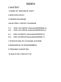
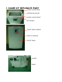
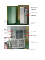
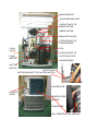
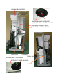
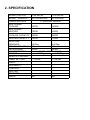
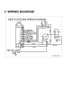
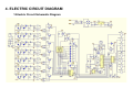
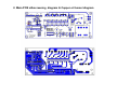
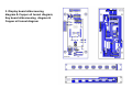
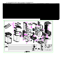
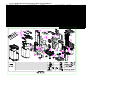
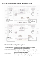
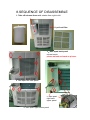
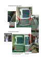
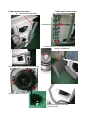
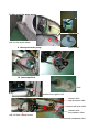
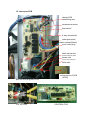
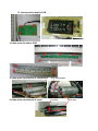
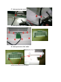
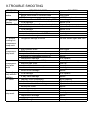
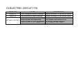
DATE OF ISSUE: 05 Feb.2009
SERVICE MANUAL
MODEL :GDC-AC12RCW/GDC-AC12RCB
GDC-AC9RCW/GDC-AC9RCS
NAME:
ITEM
PC32-06PMI,PC26-06PMI
MODEL
APPROVAL
DATE
VERSION NOTE
MADE BY
MR. YEI
INDEX
CONTENT
1.NAME OF SEPARATE PART
2.SPECIFICATION
3.WIRING DIAGRAM
4.ELECTRIC CIRCUIT DIAGRAM
5.1: GDC-AC12RCW- Explode(S2008066-2)
5.2: GDC-AC12RCB Explode(S2008050-3)
6.1: GDC-AC9RCS- Explode(S2008050-2)
6.2: GDC-AC9RCW-Explode(S2008066-1)
7.STRUCTURE OF COOLING SYSTEM
8.SEQUENCE OF DISASSEMBLE
9.TROUBLE SHOOTING
10.ELECTRIC CIRCUIT FIX
1. NAME OF SEPARATE PART
UPPER COVER-REAR
HORIZONTAL BLADE
UPPER COVER-FRONT
KEY BOARD
FRONT PANEL-MIDDLE
DISPLAY WINDOW
FRONT PANEL
WHEEL
BASE
BACK PLATE-R
PIPE OUTER
PIPE EXHAUST
PIPE INNER
LEFT
SIDE
PANEL
RIGHT SIDE
PLATE
BACK
PLATE-R
EVA FILTER
POWER
CORD
BACK PLATE-L
DRAIN
PIPE
PLUG
BACK
PLATE-BOTTOM
COND FILTER
RUBBER STOPPER
MAIN BRACKET
TRAVERSE BRACKET
CAPACITANCE OF
INNER MOTOR
INNER MOTOR
BRACKET MOTOR
CAPACITANCE OF
COMPRESSOR
4-WAY
VALVE
PCB
CAPACITANCE OF
OUTTER MOTOR
PUMP
MOTOR
COMPRESSOR
显示基板
OUTTER
MOTOR
WATER MOTOR
MOTOR BRACKET FOR WATER MOTOR
WHEEL WATER
EVAPORATOR
FIXER OF
CORD
TEMPERATURE
SENSOR
CONDENSER
COIL TEMPERATURE SENSOR
HOUSING BLOWER,TOP
WHEEL BLOWER SCREW OF
φ215,ABS+GF
WHEEL BLOWER
HOUSING BLOWER, BACK
HOUSING BLOWER, FRONT
CAPILLARY
STRAINER
DRAIN PAN
BLOWER FAN,∮240,ABS+GF
SCREW OF WHEEL BLOWER
L-JOINER
2. SPECIFICATION
MODEL (UNITED)
PC26-06PMI
MODEL(DIMPLEX) GDC-AC9RCW/S
POWER SOURCE
MAX POWER
COOLING
MAX POWER
HEATING
PC32-06PMI
AC12RCW/B
1∮220-240V 50Hz AC
1250W
1480W
1350W
1530W
COOLING CAPACITY 2600W
3500W
HEATING CAPACITY 3000W
3700W
MOISTURE
REMOVED
AIR VOLUME (M³/H)
REFRIGERANT
UNIT DIMENSION
WEIGHT
REMOTE CONTROL
32L/Day
400
R410A
Y
50 L/Day
500
R410A
W 476 x D 358 x H 840
29.5Kg
30.5Kg
Y
TIMER SETTING
0 ~ 24 hrs
0 ~ 24 hrs
SLEEP
DEHUMIDITY
CONTROL
HEATING
DEFROST
ANION
Y
Y
Y
Y
Y
N/A
Y
Y
Y
Y
Y
N/A
3. WIRING DIAGRAM
4. ELECTRIC CIRCUIT DIAGRAM
1:Electric Circuit Schematic Diagram
2. Main PCB silkscreening diagram & Copper oil tunnel diagram
3. Display board silkscreening
diagram & Copper oil tunnel diagram;
Key board silkscreening diagram &
Copper oil tunnel diagram
5.1: PC32-06PMI-AUSTRALIA (GDC-AC12RCW)- Explode(S2008066-2)
ITEM
1
2
3
4
5
6
7
8
9
10
11
12
13
14
15
16
17
18
19
20
21
22
23
24
PART NO.
210314-0AXY
210519-0Y-1-3
410259-0Y-1
210178-DFXY
210446-0Y-3
210520-0Y-3
110146-00XY
210333-9BAY
210491-0Y-1
210180-CD2Y
210182-CDAY
110144-0EXY
110168-0Y-1
700161-00-3
210016-1B2Y
720044-0AXY
210363-0AXY
750026-0AXY
780165-AY-1-H
780166-0Y-1-H
740007-20XY
310020-0Y-1
210325-DEXY-F
290025-00XY-H
PART NAME
FRONT PANEL
UPPER COVER-FRONT
HOUSING BLOWER,TOP
LEFT SIDE PLATE
RIGHT SIDE PLATE
UPPER COVER-REAR
MOUNT FOR UPPER COVER-FRONT
EVA FILTER 7TH
BACK PLATE-L
BACK PLATE-BOTTOM
COND FILTER
MAIN BRACKET
TRAVERSE BRACKET
COMP
BLOWER FAN,∮240,ABS+GF
PUMP MOTOR
BASE FOR PUMP MOTOR
water-level regulator
OUTLET FOR EVAPORATOR
INLET FOR CONDENSER
STRAINER
RUBBER STOPPER
BASE,5C
WHEEL TWP
Unit Price(USD)
ITEM
25
26
27
28
29
30
31
32
33
34
35
36
37
38
39
40
41
42
43
44
45
46
47
48
PART NO.
PART NAME
110176-AY-2
MOTOR BRACKET FOR WATER MOTOR
780164-0Y-5
SUCTION TUBE
210492-0Y-1
BACK PLATE-R ,5C
720075-AY-3
MOTOR WATER
110139-00XY
L-JOINER
110136-0DXY
BRACKET MOTOR
720072-0Y-3
INNER MOTOR
720078-0Y-3
OUTER MOTOR
210449-0Y-3
WHEEL BLOWER,φ215,ABS+GF
210428-AY-3
BACK PLATE-R
710132-0CAY
CONDENSER
210468-0Y-2
PIPE INNER
780202-0Y-1-H
JOINER FOR CAPILLARY
290008-A0XY
PIPE EXHAUST
210469-AY-2
PIPE OUTER
210483-0Y-1
Join for horizontal blade
210484-AY-1
Lever for horizontal blade
780203-0Y-26
CAPILLARY, 0.8*2.0*500L
780203-0Y-27
CAPILLARY, 0.8*2.0*550L
210549-0Y-1
wire holder-top
210550-AY-1
wire holder-bottom
410210-0Y-2
HOUSING BLOWER,BACK
410211-0Y-2
HOUSING BLOWER, FRONT
410189-AY-1-A0604 Enclosure for housing blower
Unit Price(USD)
ITEM
49
50
51
52
53
54
55
56
57
58
59
60
61
62
63
64
65
66
67
68
69
PART NO.
PART NAME
190004-004Y
Clip for capacitor
710133-4BAY
EVAPORATOR
410188-AY-1-X DRAIN PAN
800124-0Y-3-1-K MAIN PCB ,HEAT PUMP
800142-0Y-1-1 DISPLAY PCB+LED MODULE
210521-0Y-4
FRONT PANEL-MIDDLE
210522-0Y-1
KEY BOARD
730001-10XY
CAP, 30uF 450V
730052-0Y-1
CAP, 3.5uFx450VAC
730049-00XY
CAP, 3.0uFx450VAC
210186-0BXY
WHEEL WATER
410262-0Y-1
PACKING TOP PSF
410263-0Y-1
PACKING BOTTOM PSF
210481-BY-1
Horizontal blade A
210482-BY-1
Horizontal blade B
780167-0Y-1-H DISCHARGE TUBE
740010-00XY
4-WAY VALVE
780168-0Y-1-H INLET FOR CONDENSER
230028-0Y-3
WINDOW KIT A
230029-0Y-1
WINDOW KIT B
280008-10XY
Insulator Plate
610061-0Y-34
CARTON
760045-0Y-4-1 POWER CORD
800074-80XY-K REMOTE CONTROLLER
620179-0Y-6
MANUAL
870010-A0XY
TEMP. SENSOR
Unit Price(USD)
5.2: PC32-06PMI-AUSTRALIA-BLACK (GDC-AC12RCB) Explode(S2008050-3)
ITEM
1
2
3
4
5
6
7
8
9
10
11
12
13
14
15
16
17
18
19
20
21
22
23
24
PART NO.
210314-8AXY
210519-0Y-1-3
410259-0Y-1
210178-EFXY
210446-0Y-1
210520-0Y-1
110146-00XY
210333-1BAY-1
210491-0Y-4
210180-BD2Y
210182-BDAY-1
110144-0EXY
110168-0Y-1
700161-00-1
210016-1B2Y
720044-0AXY
210363-0AXY
750026-0AXY
780165-AY-1-H
780166-0Y-1-H
740007-20XY
310020-0Y-1
210325-FEXY-F
290025-00XY-H
PART NAME
FRONT PANEL,BLACK
UPPER COVER-FRONT
HOUSING BLOWER,TOP
LEFT SIDE PLATE,BLACK
RIGHT SIDE PLATE ,BLACK
UPPER COVER-REAR,BLACK
MOUNT FOR UPPER COVER-FRONT
EVA FILTER 7TH,BLACK
BACK PLATE-L ,BLACK
BACK PLATE-BOTTOM ,BLACK
COND FILTER,BLACK
MAIN BRACKET
TRAVERSE BRACKET
COMP
BLOWER FAN,∮240,ABS+GF
PUMP MOTOR
BASE FOR PUMP MOTOR
water-level regulator
OUTLET FOR EVAPORATOR
INLET FOR CONDENSER
STRAINER
RUBBER STOPPER
BASE,BLACK
WHEEL TWP
Unit Price(USD)
ITEM
25
26
27
28
29
30
31
32
33
34
35
36
37
38
39
40
41
42
43
44
45
46
47
48
Unit Price(USD)
PART NO.
PART NAME
110176-AY-2
MOTOR BRACKET FOR WATER MOTOR
780164-0Y-5
SUCTION TUBE
210492-0Y-3
BACK PLATE-R ,BLACK
720075-AY-3
MOTOR WATER
110139-00XY
L-JOINER
110136-0DXY
BRACKET MOTOR
720078-0Y-3
INNER MOTOR
720071-0Y-3
OUTER MOTOR
210449-0Y-3
WHEEL BLOWER,φ215,ABS+GF
210428-AY-2
BACK PLATE-R ,BLACK
710132-0CAY
CONDENSER
210468-0Y-3
PIPE INNER,BLACK
780202-0Y-1
JOINER FOR CAPILLARY
290008-A0XY
PIPE EXHAUST
210469-AY-3
PIPE OUTER,BLACK
210483-0Y-1
Join for horizontal blade
210484-AY-1
Lever for horizontal blade
780203-0Y-27
CAPILLARY, 0.8x2.0xL500
780203-0Y-26
CAPILLARY, 0.8x2.0xL550
210549-0Y-1
wire holder-top
210550-AY-1
wire holder-bottom
410210-0Y-2
HOUSING BLOWER,BACK
410211-0Y-2
HOUSING BLOWER, FRONT
410189-AY-1-A0604 Enclosure for housing blower
ITEM
49
50
51
52
53
54
55
56
57
58
59
60
61
62
63
64
65
66
67
68
69
PART NO.
PART NAME
190004-004Y
Clip for capacitor
710133-4BAY
EVAPORATOR
410188-AY-1-X DRAIN PAN
800124-0Y-3-1-K MAIN PCB ,HEAT PUMP
800142-0Y-1-1 DISPLAY PCB+LED MODULE
210521-0Y-3
FRONT PANEL-MIDDLE,BLACK
210522-0Y-1
KEY BOARD
730001-10XY
CAP, 30uF 450V
730052-0Y-1
CAP, 3.5uFx450VAC
730049-00XY
CAP, 3.0uFx450VAC
210186-0BXY
WHEEL WATER
410262-0Y-1
PACKING TOP PSF
410263-0Y-1
PACKING BOTTOM PSF
210481-BY-1
Horizontal blade A
210482-BY-1
Horizontal blade B
780167-0Y-1-H DISCHARGE TUBE
740010-00XY
4-WAY VALVE
780168-0Y-1-H INLET FOR CONDENSER
230028-0Y-3
WINDOW KIT A
230029-0Y-1
WINDOW KIT B
280008-10XY
Insulator Plate
610061-0Y-31 CARTON
760045-0Y-4-1 POWER CORD
800074-90XY-K REMOTE CONTROLLER,BLACK
620179-0Y-6
MANUAL
870010-A0XY
TEMP. SENSOR
Unit Price(USD)
6.1: PC26-06PMI-AUSTRALIA-SILVER (GDC-AC9RCS)- Explode(S2008050-2)
ITEM
1
2
3
4
5
6
7
8
9
10
11
12
13
14
15
16
17
18
19
20
21
22
23
24
PART NO.
210314-1AXY
210519-0Y-1-3
410259-0Y-1
210178-DFXY
210446-0Y-3
210520-0Y-3
110146-00XY
210333-9BAY
210491-0Y-1
210180-CD2Y
210182-CDAY
110144-0EXY
110168-0Y-1
700162-00-3
210016-1B2Y
720044-0AXY
210363-0AXY
750026-0AXY
780165-0Y-3
780166-0Y-1-H
740007-4AXY
310020-0Y-1
210325-DEXY-F
290025-00XY-H
PART NAME
FRONT PANEL,SILVER
UPPER COVER-FRONT
HOUSING BLOWER,TOP
LEFT SIDE PLATE
RIGHT SIDE PLATE
UPPER COVER-REAR
MOUNT FOR UPPER COVER-FRONT
EVA FILTER 7TH
BACK PLATE-L
BACK PLATE-BOTTOM
COND FILTER
MAIN BRACKET
TRAVERSE BRACKET
COMP, C-1RN75H5D R410a
BLOWER FAN,∮240,ABS+GF
PUMP MOTOR
BASE FOR PUMP MOTOR
water-level regulator
OUTLET FOR EVAPORATOR
INLET FOR CONDENSER
STRAINER
RUBBER STOPPER
BASE,5C
WHEEL TWP
Unit Price(USD)
ITEM
25
26
27
28
29
30
31
32
33
34
35
36
37
38
39
40
41
42
43
44
45
46
47
48
PART NO.
110176-AY-2
780164-0Y-5
210492-0Y-1
720075-AY-3
110139-00XY
110136-0DXY
720072-0Y-3
720071-0Y-3
210449-0Y-3
210428-AY-3
710132-2BAY
210468-0Y-2
780202-0Y-1-H
290008-A0XY
210469-AY-2
210483-0Y-1
210484-AY-1
780203-0Y-7
PART NAME
MOTOR BRACKET FOR WATER MOTOR
SUCTION TUBE
BACK PLATE-R
MOTOR WATER
L-JOINER
BRACKET MOTOR
INNER MOTOR
OUTER MOTOR
WHEEL BLOWER,φ215,ABS+GF
BACK PLATE-R
CONDENSER
PIPE INNER
JOINER FOR CAPILLARY
PIPE EXHAUST
PIPE OUTER
Join for horizontal blade
Lever for horizontal blade
CAPILLARY, 1.1x2.4xL600
210549-0Y-1
wire holder-top
210550-AY-1
wire holder-bottom
410210-0Y-2
HOUSING BLOWER,BACK
410211-0Y-2
HOUSING BLOWER, FRONT
410189-AY-1-A0604 Enclosure for housing blower
Unit Price(USD)
ITEM
49
50
51
52
53
54
55
56
57
58
59
60
61
62
63
64
65
66
67
68
69
PART NO.
PART NAME
190004-004Y
Clip for capacitor
710131-AEAY
EVAPORATOR
410188-AY-1-X DRAIN PAN
800124-0Y-3-1-K MAIN PCB ,HEAT PUMP
800142-0Y-1-1 DISPLAY PCB+LED MODULE
210521-0Y-6
FRONT PANEL-MIDDLE,OVERALL PAINT
210522-0Y-1
KEY BOARD
730002-20XY
CAP, 30uF 450VAC(45)VDE
730052-0Y-1
CAP, 3.5uFx450VAC
73000800XY
CAP, 2.5uFx450VAC
210186-0BXY
WHEEL WATER
410262-0Y-1
PACKING TOP PSF
410263-0Y-1
PACKING BOTTOM PSF
210481-BY-1
Horizontal blade A
210482-BY-1
Horizontal blade B
780167-0Y-3
DISCHARGE TUBE
740010-00XY
4-WAY VALVE
780168-0Y-2
INLET FOR CONDENSER
230028-0Y-3
WINDOW KIT A
230029-0Y-1
WINDOW KIT B
280008-10XY
Insulator Plate
610061-0Y-30
CARTON
760045-0Y-4-1 POWER CORD
800074-80XY-K REMOTE CONTROLLER
620179-0Y-6
MANUAL
870010-A0XY
TEMP. SENSOR
Unit Price(USD)
6.2: PC26-06PMI-AUSTRALIA (GDC-AC9RCW)-Explode(S2008066-1)
ITEM
1
2
3
4
5
6
7
8
9
10
11
12
13
14
15
16
17
18
19
20
21
22
23
24
PART NO.
210314-0AXY
210519-0Y-1-3
410259-0Y-1
210178-DFXY
210446-0Y-3
210520-0Y-3
110146-00XY
210333-9BAY
210491-0Y-1
210180-CD2Y
210182-CDAY
110144-0EXY
110168-0Y-1
700162-00-3
210016-1B2Y
720044-0AXY
210363-0AXY
750026-0AXY
780165-0Y-3
780166-0Y-1-H
740007-4AXY
310020-0Y-1
210325-DEXY-F
290025-00XY-H
PART NAME
FRONT PANEL
UPPER COVER-FRONT
HOUSING BLOWER,TOP
LEFT SIDE PLATE
RIGHT SIDE PLATE
UPPER COVER-REAR
MOUNT FOR UPPER COVER-FRONT
EVA FILTER 7TH
BACK PLATE-L
BACK PLATE-BOTTOM
COND FILTER
MAIN BRACKET
TRAVERSE BRACKET
COMP, C-1RN75H5D R410a
BLOWER FAN,∮240,ABS+GF
PUMP MOTOR
BASE FOR PUMP MOTOR
water-level regulator
OUTLET FOR EVAPORATOR
INLET FOR CONDENSER
STRAINER
RUBBER STOPPER
BASE,5C
WHEEL TWP
Unit Price(USD)
ITEM
25
26
27
28
29
30
31
32
33
34
35
36
37
38
39
40
41
42
43
44
45
46
47
48
PART NO.
110176-AY-2
780164-0Y-5
210492-0Y-1
720075-AY-3
110139-00XY
110136-0DXY
720072-0Y-3
720071-0Y-3
210449-0Y-3
210428-AY-3
710132-2BAY
210468-0Y-2
780202-0Y-1-H
290008-A0XY
210469-AY-2
210483-0Y-1
210484-AY-1
780203-0Y-7
PART NAME
MOTOR BRACKET FOR WATER MOTOR
SUCTION TUBE
BACK PLATE-R
MOTOR WATER
L-JOINER
BRACKET MOTOR
INNER MOTOR
OUTER MOTOR
WHEEL BLOWER,φ215,ABS+GF
BACK PLATE-R
CONDENSER
PIPE INNER
JOINER FOR CAPILLARY
PIPE EXHAUST
PIPE OUTER
Join for horizontal blade
Lever for horizontal blade
CAPILLARY, 1.1x2.4xL600
210549-0Y-1
wire holder-top
210550-AY-1
wire holder-bottom
410210-0Y-2
HOUSING BLOWER,BACK
410211-0Y-2
HOUSING BLOWER, FRONT
410189-AY-1-A0604 Enclosure for housing blower
Unit Price(USD)
ITEM
49
50
51
52
53
54
55
56
57
58
59
60
61
62
63
64
65
66
67
68
69
PART NO.
PART NAME
190004-004Y
Clip for capacitor
710131-AEAY
EVAPORATOR
410188-AY-1-X DRAIN PAN
800124-0Y-3-1-K MAIN PCB ,HEAT PUMP
800142-0Y-1-1 DISPLAY PCB+LED MODULE
210521-0Y-4
FRONT PANEL-MIDDLE
210522-0Y-1
KEY BOARD
730002-20XY
CAP, 30uF 450VAC(45)VDE
730052-0Y-1
CAP, 3.5uFx450VAC
73000800XY
CAP, 2.5uFx450VAC
210186-0BXY
WHEEL WATER
410262-0Y-1
PACKING TOP PSF
410263-0Y-1
PACKING BOTTOM PSF
210481-BY-1
Horizontal blade A
210482-BY-1
Horizontal blade B
780167-0Y-3
DISCHARGE TUBE
740010-00XY
4-WAY VALVE
780168-0Y-2
INLET FOR CONDENSER
230028-0Y-3
WINDOW KIT A
230029-0Y-1
WINDOW KIT B
280008-10XY
Insulator Plate
610061-0Y-33
CARTON
760045-0Y-4-1 POWER CORD
800074-80XY-K REMOTE CONTROLLER
620179-0Y-6
MANUAL
870010-A0XY
TEMP. SENSOR
Unit Price(USD)
7.STRUCTURE OF COOLING SYSTEM
The funtion for each part of system:
1.COMPRESSOR: Compressing gas state refrigerant to be high
temperature-high pressure liquid
2.CONDENSATOR:Releasing heat.Let high temperature refrigerant
releasing heat and become high pressure- regular
temperature state refrigerant.
Straining impurities of water vapor in the Refrigeration
3.STRAINER:
system, preventing capillary plugging
4.CAPILLARY:
refrigerant become low temperature-low pressure gas
state after through capillary.(Capillary is a thin brass,
from small-diameter(Capillary) to large
diameter(evaporator),area increase,high pressureregular temperature state refrigerant become low
temperature-low pressure gas state.)
5.EVAPORATOR: Absorb heat.Refrigerant become gasification in the
evaporator.(low temperature-low pressure state)
6.OUTTER MOTOR When cooling funtion:
Exhausung heat air from condensator to out door.
When heating funtion:
Exhausung cool air from evaporator to out door.
7.INNER MOTOR: When cooling funtion: Inspire indoor air through
condensator to heat indoor air.
When heating funtion: Inspire indoor air through
evaporator to cool indoor air.
8. 4-WAY VALVE:
Exchange the direction of flow to refrigerant, the
evaporator and condensator swap
The thorey for cooling funtion:
Using compressor to compress refrigerant to be high temperature-high
pressure liquid and through condensator (Using Fan to exhaust the heat to
outdoor).Refrigerant entry capillary after cool and become low temperature
liquid state to flow in evaporator.Refrigerant become gasification in the
evaporator and absorb heat,the temperature of evaporator low.(Using Fan
to inspire indoor air through evaporator to cool indoor air) Compressor
insprie gas state refrigerant again. Repeat this cycle step reached indoor
cooling.
The thorey for heating funtion:
Using 4-way valve to swap the evaporator and condensator, blow hot air to
indoor and exhaust cool air to outdoor.
8.SEQUENCE OF DISASSEMBLE
1. Take off exhaust from unit: rotates from right to left
2. pull out filter
3、take apart back panel
unload screw
please unload red mark as picture
a. take apart left back panel
tear PE stick
c. take apart
right back
upper panel
b. take apart right bottom panel
4. take apart left & right panel
5. take apart front panel
a: unload both side screw
b: pull out front panel
c: pull out all of connecting wire
on PCB
6. take apart inner motor
a:remove the evaporator
7. take apart outter motor
unload screw
a: unload screw on condensor both side
remove condenser
unload the screw of blower from air-outlet
unload 3 screw of motor
unload the screw of blower
from air-outlet
8. take apart the water motor
water motor
pull out the water wheel
9. take apart water pump
water wheel
10. take arapt float
float
rotates from right to left
11. take apart 4 way valve
connect with
high pressure tube
connect with eva outlet
connect with
low pressure tube
pull coil from unload screw
connect with condenser inlet
12. take apart PCB
display PCB
connecting wire
temperature sersor
float switch
4 way valve(white)
water pump(red)
water motoraril(black)
inner motor plug
7.拆主基板
依次取下各固定柱
把外面一条束线剪断
black yellow wire
connect relay NC point
brown wire
connect relay COM point
white wire
8、拆打水马达
unload screw of PCB
(4PCS)
pull out all of plug from PCB
Cut The Fixer
CONTROL PCB
13. take apart the display PCB
14. take apart the button PCB
15. take apart capacitance of compressor
blue wire(power)
16. take apart capacitance of motor
red wire
white wire
17. take apart power cord
18. take apart top cover and front cover
19. take apart vane of air outlet
unload screw both side on panel
9.TROUBLE SHOOTING
PROBLEM
POSSIBLE CAUSE
1:without 1:power cord damage or inner wire broken
2:power cord loose or terminal loose
action
3:PCB damage
2:abnormal 1:bad connect main PCB with display PCB
2:PCB damage
display
3:show E7 1: water full (water from Evaporator to plate)
2:float damage
3:PCB damage
4:wheel water stuck
5: connecter water motor with PCB loose
6:water motor damage
4:without 1:refrigerant leakage or stuck
cooling but
compressor
keep work
1:wire connect loose
5:
compressor 2:PCB damage
stop work
3:capacitance of compressor damage
4:protecter of compressor switch off
5:compressor damage
1:room temperature over 35 ℃
6:
compressor 2:exhaust pipe stuck
stop after
3:outter motor stuck
work
4:outter motor wire connect loose
5:outter motor damage
7:cooling
1:PCB damage
only without
2:4 way valve damage
heating
1:capillary touch something
8:noise
2:fan bolwer touch styrofoam
3:water wheel touch something
4:noise from motor
5:noise from compressor
9:fan motor 1:vane of fan stuck
2:connect loose
stop work
3:capacitance damage
4:motor gamage
5: PCB damage
SOLUTION
replace
insert again
fix PCB or replace it
connect again
replace PCB
drain out
replace the float switch
replace PCB
clean up
insert again
replace
join with solder again and refill
insert again
fix or replace
replace
replace
fix or replace
over temperature range
clean up
clean up
insert again
replace
fix or replace
replace
adjust capillary
adjust fan
adjust water wheel
replace
replace
clean up
insert again
replace
replace
fix or replace
10.ELECTRIC CIRCUIT FIX
PROBLEM
SHOW E1
SHOW E2
CAUSE
1:room temperature sensor damage
1:eva temperature sensor damage
1:without power supply
2:without power into transformer
WITHOUT ACTION
3:without power out from transformer
4:without power out from 7805
HOW TO FIX IT
replace the sensor or call service center
replace the sensor or call service center
check power and plug connect on or not
check power fuse connect or not
transformer damage,replace it
replace 7805 (mark on IC3)