1
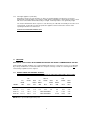
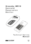
AIRA RADIANT TUBE HEATERS
INSTALLATION, OPERATION AND
SERVICE MANUAL
‘U’ TUBE SERIES
OWNER OPERATING INSTRUCTIONS FOR RTH RADIANT TUBE HEATERS
The RTH is an overhead radiant heating system for industrial and commercial buildings. The RTH heaters are
suspended from the roof or mounted at an angle on the wall. They heat by radiation in the same was as the sun.
IMPORTANT
1.
2.
3.
4.
5.
This appliance shall only be installed by a qualified person in accordance with the Gas Safety Regulations.
This appliance must be earthed.
Never rest anything, especially ladders, against the heater.
Do not store flammable materials near the appliance.
Do not spray aerosols etc near the appliance while it is in operation.
WARNING: Should the presence of any of the following materials be likely in the room or building where the
appliance is installed, then the appliance burner air intake and the fan must be vented to the outside air:
GENKLENE / TRIKLONE / PERKLONE / METHOKLONE / ARKLONE (FREONI)
TO START HEATER:
1.
2.
3.
Turn on the gas supply.
Ensure that the time switch and room thermostat (if fitted) are set and calling for heat.
Switch on electrical system. Appliance should start up. After about 45 seconds unit will indicate either
amber and green lights (3 light unit) or a red light (1 light units) to indicate main flame is on. On RTH160
there is a red light only if lockout has occurred.
If lockout occurs on any appliance, switch off power supply, check gas is on, and turn power back on to
rest unit. In the gas of frequent lockout, contact the service engineer, supplier or installer.
TO STOP HEATER:
1.
2.
Switch off electrical supply.
If unit is to be off for more than a few days, turn off gas supply at appliance gas cock.
IT IS IMPORTANT TO ENSURE EFFICIENT OPERATION OF THE HEATER THAT IT IS SERVICED AND
INSPECTED REGULARLY.
1
INSTALLATION INSTRUCTIONS
RTH RADIANT HEATERS MODEL 60/80, 110 & 160
AGA APPROVAL NO. 4258 –NG, TG, TLP, and LPG
(RTH 110 NG & LPG ONLY & RTH 160 NG ONLY)
SEC ACCEPTANCE NO. LA 86435
Appliance ratings, injector sizes, gas pressures etc. are detailed in the maintenance section, and stamped on the
appliance data plate.
READ THE FOLLOWING INSTRUCTIONS CAREFULLY BEFORE COMMENCING INSTALLATION
1. GENERAL
The appliance shall be installed in accordance with the manufacturer’s instructions, the Uniform Building
Regulations, the Australian Gas Association’s “Installation Code for Gas Burning Appliances and/or Equipment ,
AGA Installation Code for Gas Pipe Sizing, Local Gas Fitting Regulations, Local electric Supply Authority
Regulations and any other statutory regulations. A Notice of Intent to Install should be lodged with the relevant
Municipal Authority and local gas authority prior to installation.
2. DELIVERY
The customer or installer, upon delivery of the appliance shall immediately remove any packaging material and
inspect the appliance for damage and/or missing components and shall ensure that the appliance is designed
and supplied for the gas with which it is to be used. Any discrepancies or damage shall immediately be reported
to the supplier.
NOTE: GAS SAFETY REGULATIONS
It is the law that all gas appliances are installed and commissioned by competent persons in accordance with the
above regulations. Failure to install appliances correctly could lead to prosecution and may void building
insurance. It is in your own interests and those of safety to ensure that the law is complied with.
3. LOCATION AND CLEARANCES
RTH radiant tube heaters are suitable for indoor installation only. The units shall be installed in locations which
allow for easy service access and in which ventilation and other requirements can be met. Clearances from
combustible materials shall be provided in accordance with manufacturer’s data. Mounting heights shall be as
detailed below:Minimum mounting height:
Horizontal mounting (standard suspended) – 3.6m (4.5m RTH 110)
Wall (angled) mounting
- 3.0m (3.6m RTH 110)
RTH 160 may not be wall mounted.
4. VENTILATION REQUIREMENTS
Ventilation shall be in accordance with requirements for FLUELESS radiant tube heaters if an unflued
system is required and with AG 601 Installation Code.
Specific requirements for unflued radiant tube heaters are also given in AGL or Gas and Fuel Corporation
Regulations. As a guide, provided ventilation and height requirements can be met, a building volume of 420m3
would be required for an unflued RTH 80.
If in doubt, contact the gas supply authority or install a flued appliance.
For FLUED installations the following ventilation areas must be proved:
If ventilation to outside; two openings are required, one near ground level and one near the eaves of the building.
Each vent shall have a free area of not less then 6cm2 per 5MJ of hourly gas consumption. If ventilating to
another room in the building the ventilation areas shall be doubled. Refer to table below:
2
MODEL
RTH 60
RTH 80
RTH 110
RTH 160
VENT AREA TO OUTSIDE
2x
cm2
2x
76
102
140
200
VENT AREA TO ADJACENT ROOM
cm2
152
205
280
410
5. FLUE INSTALLATION
Flue must be 100mm twin skin type and shall be AGA Approved. Flue installation shall also comply with
AG 601 installation code. Flues extending through the roof shall terminate no less than 600mm from the nearest
part of the roof. Flues terminating on an outside building wall shall be specifically approved by the gas authority.
No damper may be installed in the flue and the flue must be terminated with an AGA Approved cowl. Flued RTH
appliances shall be fitted with a draught diverter. These and approved twin skin flue components are available
from AIRA Pty Ltd.
6. TECHNICAL DATA
Data below applies to NATURAL GAS units only. Refer to maintenance instructions and data plate for injector
size, setting pressures wtc. For other gases.
DIMENSIONS (Standard length ‘U’ tubed versions only)
Overall length:
5575 (18’6”) RTH 60/80 or 7000 (21’) RTH 110
10360 (34’) RTH 160
Distance between outermost suspension points 4810, 6500 or 10000
Overall width 480 (1’7”) RTH 60/80 & RTH 160 or 600 (24”) RTH 110
Overall height 275 (11”) RTH 60/80 & RTH 160 or 6000 (24”) RTH 160
MOUNTING HEIGHT
RTH 60/80
3.6m minimum
RTH 110
4.5m minimum
RTH 160
3.6m minimum
INPUT
RTH 60 – 17.5 kW (60,000 Btu/h)
RTH 80 – 23.5 kW (80,000 Btu/h)
RTH 110 – 32.0 kW (110,000 Btu/h)
RTH 160 – 47.0 kW (160,000 Btu/h)
GAS SUPPLY
NG
Inlet pressure Minimum 1.0 kPa
Maximum 2.0 kPa
LPG *
Inlet pressure Minimum 2.5 kPa
Maximum 3.5 kPa
TG/TLP** Inlet pressure Minimum 0.6 kPa
Maximum 1.0 kPa
* RTH 110 & RTH 160
** Applies RTH 60/80 Only
GAS CONNECTION
All Units, All Gases; ½” BSP
WEIGHT
RTH 60/80 – 60kg
RTH 110 – 80kg
RTH 160 – 120kg
3
ELECTRICAL SUPPLY
240V, 1 Phase, 50 Hz, 3 Amp
REFLECTORS
1.00mm aluminum
EMITTER TUBES
77 OD 1.6mm spiral wound steel (102 OD firing tube on RTH 110)
OPTIONAL EXTRAS
1. 0.6mm stainless steel reflectors
2. 900mm flexible gas line
3. Chain, shackles and turnbuckles for mounting
4. Wall mounting brackets
5. 100mm draught diverter for flued installations
6. Installation kit (set of parts 2 & 3 above).
7. ASSEMBLY OF SUSPENDED UNITS
Refer to figures attached.
7.1
Set the radiant tubes at least 150mm above the floor (preferably under the suspension points) and parallel
about 200mm apart.
7.2
Locate end hanger on U bend (This plate always has two equally sized holes). Locate U clamp on each U
bend end.
On RTH 110 units only fit 75-100mm adaptor on U bend and secure U clamp. Locate 100mm U clamp on
adaptor.
7.3
Slide firing tube and return tubes 50mm into U bend ends and tighten U clamps.
7.4
Slide remaining hanger plates along tube assembly as follows:
RTH 60/80 – 1 to approximate centre of tube length,
1 at burner box end
RTH 110 - 1 to approximately 3 metres from U bend
1 to approximately 1.2 metres from burner box end,
1 at burner box end.
7.5
For RTH 160 assemble as for RTH 60/80 except that two sets of parts are used.
7.6
If supplied unassembled, attach reflector brackets to hanger plates using bolts and nuts provided. On end
hangers, fit one bracket only, flange point towards centre of appliance. On intermediate hangers, fit one
bracket each side of hanger.
7.7
PLASTIC COATING MUST BE PEELED OFF BEFORE REFLECTORS ARE FITTED. Attach reflectors
to reflector brackets using nuts and bolts provided. Bolts must point upwards, and nuts must only
hand tight. If tube/reflector/bracket set has been preassembled before delivery, reflector
attachment bolts must be loosened after erecting appliance and before commissioning. On RTH
110, use remaining nuts and bolts to join halves of reflectors together. Nuts must only be hand tight.
Short reflectors should be located at burner box end.
7.8
On RTH 60/80 and RTH 110, attach fan unit to return tube using U clamp. Note that flue outlet must be
horizontal on unflued appliances, vertical on flued appliances. For RTH 160 refer section 9.5 below.
4
7.9
ASSEMBLY OF WALL MOUNTED UNITS
T he unit is assembled as above, however, the wall mounting kit will be require to install the appliance.
Do not attach the fan unit until the tube/reflector assembly has been mounted on the wall.
8. SUSPENSION – STANDARD UNITS
Refer to Technical Data to ensure minimum mounting height detail is observed.
The heaters incorporate 3 or 4 pairs of hanging points, one pair at each end of the tubes and one pair at each
intermediate hanger. The suspension holes give clearance for 10mm dia bolts or hooks. Alternatively shackles
and turnbuckles may be used as recommended.
The heaters should be suspended with 5mm welded galvanized link chain, 10mm drop rods or brackets. Firm
anchorage must be mad onto the roof structure to carry the whole weight of the heater. Beam clamps, joist clips
or 12mm bolts should be used on metal structures and at least a 20mm coach bolt with hook on wooden beams.
9. FLUE INSTALLATIONS
ALL FLUED RTH HEATERS MUST E FITTED WITH A DRAUGHT DIVERTER. THIS COMPONENT MUST BE
ORDERED WITH THE HEATER.
9.1
On RTH 60/80 & 110 locate the fan outlet so that the 75mm square outlet spigot is vertical. Attach the
draught diverter with screws as required. For RTH 160 see section 9.5 below.
9.2
Install twin skin 100mm flue in accordance with instructions and regulations. FLUE MUST BE
SUPPORTED AND NOT WEIGH DOWN ON HEATER UNIT. A split flue socket should be used on the
outlet of the draught diverter to enable the fan assembly to be removed without disturbing the flue.
9.3
Complete the flue with an approved terminal and ensure the flue outer skin is sealed where it passes
through the roof.
9.4
On RTH 60/80 and RTH 110 fit the burner assembly to the RIGHT HAND tube alongside the fan unit,
using the remaining 3” ‘U’ clamp. Ensure unit is pushed not more than 50mm onto firing tube.
9.5
On RTH 160 fir the complete burner and fan assembly to the return and firing tubes using the remaining 4
‘U’ clamps. Ensure burner spigots are pushed not more than 50mm onto firing tubes. Check that return
tube expansion pieces are free to move. Adjust central hanger chains to ensure that unit hangs level.
RADIANT TUBES MUST NOT PROJECT INSIDE THE ADAPTOR BEYOND THE PARALLEL
SECTION.
9.6
On flued RTH 160, fit right angle adaptor to square fan outlet spigot so that new outlet spigot is vertical,
then fit draught diverter and flue as in 9.1 to 9.3 above.
9.7
Adjust the suspension chains and/or turnbuckles to ensure the unit hangs square. Tighten all ‘U’ clamp
nuts.
9.8
On RTH 60/80 and RTH 110 plug the fan unit into the electrical socket on the burner box. On RTH 160
plug fan into cord extension socket provided. The mains supply lead is fitted with a standard 3 pin plug.
Note colour code as follows:
Green / Yellow – Earth
Blue – Neutral
Brown – Active
If desired, the unit may be hard wired to a central control panel. In this case each unit must have an
individual on-off switch for reset and servicing purposes.
9.9
The gas connection must be made with a quarter turn gas cock located in an accessible location. The
final gas connection to the heater must be made with an approved armoured flexible hose. Copper tube
may be used only if an anti-vibration loop is incorporated in the tube.
9.10
The wall plate carrying the operating instructions must be located adjacent to the master electric switch,
preferably at eye level.
5
10. WALL MOUNTED INSTALLATIONS RTH 60/80 & RTH 110 ONLY
The heater must be mounted on a vertical surface, using the wall mounting kit complete with flue extension piece.
This allows the heater to be mounted at an angle of 45 degrees where perimeter heating is required.
Fit the wall brackets in place using at least two fixing positions on each bracket. The brackets must be fitted at
least 3 metres above floor level and spaced accurately to accept tube/reflector/bracket assembly. Use M10 or
3/8W bolts to attach assembly to wall brackets.
Fit fan and control unit assemblies but ensure fan unit outlet is upright and burner unit parallel to wall. Fit flue
extension piece on all wall mounted units, followed by draught diverter and flue if appliance is to be flued.
Gas supply pipe should be run to the heater and at least 300mm above and to one side of the line of the flue
outlet. An approved armoured flexible gas hose shall be used and fitted with a quarter turn gas cock in an
accessible position.
Connect electrical supply and mount wall plate as for standard units.
11. COMMISSIONING
11.1
11.2
Check that appliance is installed in accordance with installation instructions above.
With the main gas cock off, and the electrical supply isolated, turn on the main gas cock and purge all gas
lines.
11.3 Check that no foreign material is left on top of the heater or restricting the flue outlet or air inlet to the
heater controls.
11.4 Check that the fan impeller is free to spin and that the fan is plugged into the control unit.
11.5 Turn any thermostat (if fitted) on, and any time controls on.
11.6 Turn on the gas supply cock.
11.7 Remove control box outer cover.
11.8 Fit a gas manometer to the outlet test pint on the gas valve.
11.9 Connect mains electricity and witch on.
The fan should now start and the burner should fire up and operate as described below. Check that gas
pressure is correct and adjst governor on gas valve as necessary. Sht down appliance by disconnecting power
supply.
If appliance goes to lockout, disconnect power supply, wait five seconds and switch back on.
11.10 Turn off gas supply, disconnect manometer, and seal test point. Refit controls cover.
11.11 Turn on gas supply and reconnect power supply. Allow appliance to operate normally.
11.12 If multiple units are being installed, ensure that when some or all appliances are running, that gas
pressure remains adequate for correct operation.
12. BURNER SEQUENCE
12.1 ‘Three light’ appliances (RTH60/80 & 110):
As fan starts up indicator lights will change from red to amber:
Pre-purge stage will last approximately 30 seconds.
Pilot valve will open and inbuilt Ht spark generator will energize to ignite pilot flame.
After pilot flame has been burning for about 10 seconds main valve will open and a green light will be
displayed in addition to the amber light
12.2
‘One light’ appliances (RTH 60/80 & 110):
Operating sequence for valve and fan is identical to three light units except that no light indicates until
main flame is established. On one light unit a red light is displayed after main flame is established.
6
12.3
‘One light’ appliances (RTH 160):
Operating sequence for valve and fan is as above except that appliance incorporates a Technical
Components controller which senses flames in both burner compartments. Flame failure in either section
will cause lockout which will be indicated by a red light. Normal operation is not signaled by a light.
The heaters will follow the above sequences each time they are switched on manually or via a time clock
or thermostat. Instruct the user how to operate the appliance and ensure that the contents of the
operating instructions are understood.
Leave these instructions with the user.
13. SERVICING
ELECTRICAL SUPPLY MUST BE DISCONNECTED BEFORE ANY WORK IS COMMENCED ON THE UNIT.
Under normal operating conditions, it is recommended that the heater is serviced once a year. In exceptionally
dry or dusty conditions it is recommended that more frequent servicing is carried out. Servicing work must be
carried out by a qualified service engineer.
13.1
MODEL RANGE AND THERMAL OUTPUTS
NOMINAL HOURLY GAS CONSUMPTION/ INJECTOR SIZES/GAS PRESSURES/ GAS TYPES:
NG
INJ
NHGC
DIAM
TG/TLP
GAS
INJ
PRES
DIAM
NHGC
LPG
GAS
INJ
PRES
DIAM
NHGC
GAS
PRES
MODEL
MM
MJ/h
KPa
MM
MJ/h
KPa
MM
MJ/h
KPa
RTH 60
3.8
63.6
0.9
6.0
63.3
0.6
2.0
63.3
2.75
RTH 80
4.3
84.4
0.9
6.5
84.4
0.6
2.6
84.4
2.75
RTH 110
4.9
116.0
0.9
NOT AVAILABLE
3.0
116.0
2.75
RTH1 60
2 x 4.3
160.0
0.8
NOT AVAILABLE
2 x 2.6
168.0
2.75
NOTE: Pilot is operated through main injector.
7
IMPORTANT
1. Never rest anything, especially ladders, against the unit.
2. Isolate gas and electrical supplies before commencing any servicing work or component exchange.
3. Unless otherwise instructed, reassemble parts in reverse order to the instructions given blow.
ROUTINE SERVICE
Access to the controls is achieved by removing the side panel of the controls box, and the inner cover/s of the
burner compartment/s. the unit may be operated with the main cover removed, but will not when the inner
cover/s are not fitted a there will be insufficient suction to allow the air pressure switch in the control sequence.
If it is necessary to operate the unit with the main cover removed, keep the inner cover/s in place and observe the
flame through the inbuilt sight glass/es.
To remove the igniter assembly:
1. Disconnect leads from the igniter, probe and earth rod.
2. Release screws and nuts holding the assembly bracket in place at the front of the burner compartment.
3. To remove separate components, undo the two brass hexagon set screws.
Replace in reverse order.
To remove burner and injector assembly:
1. Release burner done by loosening the small set screw attaching cone to injector and slide forward to remove
cone.
2. Unscrew injector.
When replacing injector ensure sealing compound is used to provide a gas tight seal.
To remove air pressure switch:
1. Unscrew 2 screws attaching switch to its mounting bracket.
2. Pull off electrical leads, noting colour/position of leads.
3. Pull plastic air tubes off, noting positions.
Reassemble in reverse order.
To remove combined gas valve unit & sequence controller:
Early RTH 60/80 & 110 only:
1. Remove burner cone, injector and air switch as above.
2. Disconnect gas line at union fitting, and remove union connection at back of controls box.
3. Remove two bolts from valve retaining bracket.
4. Slide gas control backwards and out and disconnecting wires as necessary, noting their positions.
Reassemble in reverse order after having fitted pilot line and pipe fittings to new gas control if required. Ensure
all gas fittings are properly sealed.
To remove gas combination valve unit:
RTH 60/82 & 110 only:
1. Remove burner cone, injector and air switch as above.
2. Disconnect gas line at union fitting, and remove union connection at back of controls box.
3. Remove two bolts from valve retaining bracket.
4. Slide gas control backwards and out and disconnect connecting wires as necessary, noting their positions.
Reassemble in reverse order after having fitted pilot line and pipe fittings to new gas control if require. Ensure all
gas fittings area properly sealed.
8
To remove gas combination valve unit:
RTH 160 only:
1. Remove burner cones, injectors and air switch as above.
2. Disconnect gas line at union fitting.
3. Pull gas control forwards and out and disconnect connecting wires as necessary, noting their positions.
Reassemble in reverse order after having fitted pilot line and pipe fittings to new gas control if required. Ensure
all gas fittings are properly sealed.
To replace timer unit:
Pull off direct out of its octal socket
Ensure replacement is 24v operation and if a different brand ensure that pin connections are unchanged.
To replace control unit:
Pull of connecting wires, noting colours and positions and remove control unit after unscrewing mounting bolts.
Ensure replacement has similar model code to original unit.
To replace transformer:
1. Disconnect 240v and 24v wires from transformer.
2. Unscrew retaining bolts and lift out transformer.
When replacing transformer ensure that 240v and 24v connections are properly located.
To replace indicator light/s:
Unclip light unit and withdraw, removing wires as necessary.
When replacing unit, ensure lens is same colour (lenses may be interchanged) and light is 24 volt.
To remove fan assembly
1. Disconnect from controls box by pulling out plug.
2. Disconnect outlet from flue extension or draught diverter (if fitted).
3. Remove 3 screws holding fan to flanged pipe adaptor, or loosen nuts on ‘U’ clamp holding the adaptor to the
pipe.
Reassemble in reverse order taking care that the fan outlet is returned to the same position and that the ‘U’
clamp is properly tightened.
CHECK FOR GAS TIGHTNESS AFTER SERVICE
14. FAULT FINDING
Power and gas on – Fan no running
Cause:
a. Time clock off
b. Thermostat Satisfied
c. Supply fuse down
d. Fan disconnected
e. Fan blocked
f. Fan motor faulty
Action:
Check and reset
Check and reset
Check and replace
Check and plug in
Remove fan assembly, clean and refit
Remove fan assembly and replace
Power and gas on – fan running, no run light after 1 minute:
Cause:
Action:
a. Insufficient suction in controls box
Ensure controls box doors are tightly closed. Check all ‘U’ clamps
are tight.
9
b. pressure switch controls remain open
As above – also check flexible tube connected to air switch and bulk
head. Check pressure switch for faults. Check bulkhead adaptor
holes are clear.
c. See ‘e’ above.
Power and gas on – fan running, switch OK:
Cause:
Action:
a. No ignition sequence
Timer set wrongly (max delay 100 seconds) – reset to 30 seconds.
b. Ignition attempted but no light up
Check gas is on. Check location of flame sensor.
c. No ignition spark
Check ignition lead is connected to electrode and gas control unit.
d. Solenoid valve suspect
Check gas pressure at test point during sequence. Check
connections on gas control
Pilot lights, but no main flame:
Cause:
a. Second stage not connected
b. Pilot/main switch set to Pilot
Action:
Check connections on gas control
Switch to main
10