1
ZENER
r
VSCServiceManual
r
ZENERTECHNOLOGY
AND QUALITYASSURANCE
S i n c e 1 9 7 8Z e n e rE l e c t r i ch a s s u p p l i e dm a n yt h o u s a n d so f A C d r i v e st o A u s t r a l i a inn d u s t r i e sT.h e s e
d r i v e sh a v e b e e n i n s t a l l e di n t on u m e r o u sa p p l i c a t i o nrse s u l t i n g
i n a w e a l t ho f i n h o u s ee x p e r i e n c e .
The ZenerVSC AC motorvariablespeed controlleris the culminationof this exoertise.moderntechn o l o g ya n d i n d u s t r i aal p p l i c a t i o nrse q u i r e m e n t s .
The ZenerQualityAssuranceProgrammeensuresthat everyVSCmanufactured
has provento operate
correctlyin the productiontest bay beforedespatch.
VSC PRODUCTWARRANTY
ZenerElectricwarrantsthe VSCagainstdefectiveworkmanship
and materialsfor a periodof 24 months
from the date of despatch.Such defectswill be rectifiedfree of chargefor both labourand material,
at Zener Electric'spremisessubjectto:
1 . Z e n e r E l e c t r i c ' sc u s t o m e rr a i s i n ga n o r d e r u p o n Z e n e rf o r s e r v i c ea n d o r r e p a i r s ,s u b j e c tt o a
warrantyclaim.The order is to stateparticulars
of the modeland serialnumber,the date of original
purchaseand invoice/delivery
docketnumber.
2. All damage resultingfrom incorrectinstallation
or use otherthan in accordancewith the Instruction )
Manualissuedby Zener Electricis excludedfrom this warranty.
3 . T h e W a r r a n t yb e i n g r e n d e r e di n v a l i di f t h e p r o d u c ti s m i s u s e do r i f a n y u n a u t h o r i z eadl t e r a t i o n ,
m o d i f i c a t i oonr s u b s t i t u t i oonf a n y p a r to f t h e p r o d u c tb e m a d eo r t h e s e r i a ln u m b e ro f t h e p r o d u c t
is defacedor altered.
(both ways) is to be met by the owner if it is necessaryto returnthe
4. The cost of transportation
producto
, r a n y p a r t o f i t , t o Z e n e rE l e c t r i c ' ps r e m i s e s .
5 . A c h a r g eb e i n ga c c e p t e db y t h e o w n e rf o r t r a v e l l i ntgi m ea n d e x p e n s e si n c u r r e di n c o n n e c t i o w
n ith
warrantyserviceat the user'ssite as requestedby the owner,
6. lf the productwas not purchasedirom ZenerElectricdirectly,thena warrantyclaimmustbe lodged
w i t h t h e o r i g i n asl u p p l i e ri n t h e f i r s ti n s t a n c eR
. e p a i r sw i l l n o t b e e f f e c t e db y Z e n e rE l e c t r i cu n l e s s
a p p r o v e db y t h e o r i g i n asl u p p l i e r .
7 . G o o d s n o t o f o u r o w n m a n u f a c t u r ien c o r p o r a t e idn o u r s u p p l yo r m e r c h a n t e db y u s , c a r r yt h e i r
maker'swarrantyonly.
B . G o o d sr e t u r n e df o r c l a i mu n d e rw a r r a n t yw i l l b e a c c e p t e do n t h e c o n d i t i o nt h a ts h o u l dt h e c l a i mb e
r e j e c t e dt h e n a l l c o s t s ,i n c l u d i n gi n s p e c t i o nw, i l l b e c h a r g e dt o t h e c u s t o m e r ' a
sccount.
SAFETY
Y o u rV S C m u s t b e a p p l i e d ,i n s t a l l e d
a n d o p e r a t e di n a s a f em a n n e r l.t i s t h e r e s p o n s i b i l iot yf t h e u s e r
t o e n s u r ec o m p l i a n c e
w i t ha l l r e g u l a t i o nasn d p r a c t i c e sc o v e r i n gt h e i n s t a l l a t i oann d w i r i n go f y o u rV S C .
T h i s I n s t r u c t i oM
n a n u a ls h o u l db e c o m p l e t e l yr e a d a n d u n d e r s t o o db e f o r ea t t e m p t i n g
t o c o n n e c to r
o p e r a t et h e V S C .O n l ys k i l l e dp e r s o n n esl h o u l di n s t a ltlh i se q u i p m e n t .
THE CONTENTS
OF THIS MANUALARE SUBJECTTO CHANGE
WITHOUTNOTICE
l
r\-
TABLE OF CONTENTS
Useof thisManual
forServicing
Equipment
Required
SafetyWarnings
Glossary
of Terms
Definitions
VSCSetUpforServicing
Listof Symptoms
Module
ModuleChecking
Procedures
Transistor
BridgeRectif
ierModule
BaseDriveModules
Module
Capacitor
Module
ModuleReolacementProcedures Capacitor
ControlBoard
DCCT
Module
InputRectifier
Transistor
Module
SensorWiring
Page
2
2
3
4
4
o
B
12
13
15
to
18
1B
19
19
19
20
TABLEOF FIGURES
VSCControlBoardLayout
VSCModuleLocations
VSCBaseWiring
InternalWiring
andSparePartsList-VSC-H
InternalWiring
andSparePartsList-VSC-G
Internal
WiringandSparePartsList-VSC-S
VSCVoltageSelection
Procedure
5
7
14
21
22
23
24
ModelNumbers
VSC-H3
VSC-H4
VSC-Hs
VSC-H1O
VSC-HI3
VSC-H17
VSC-H24
VSC-H32
VSC-H38
VSC-H44
VSC-G13 VSC-S3
VSC-G17 VSC-S4
VSC-G24 VSC-Ss
VSC-G32
VSC-G3B
VSC-G44
VSC-G6O
page 1
US E O F T H I S MA N U A L
This manualis intendedas a guideto findingand repairingfaultsin the ZenerVSC.For the
experienced
servicepersonit provides
alltheinformation
necessary
to isolate
a faultymoduleand
replaceit.
Thismanualdoesnotcontaininformation
regarding
therepairof faultymodules
aswe recommend
thatall faultymodulesbe returned
Io ZenerElectric
or an authorized
distributor
for repair.Thisis
becauseeach moduleis complexand in orderto be surethey functionproperly,they must
conformto comprehensive
testspecifications,
furtherdamagecouldresult.
otherwise
It is assumedthatthe personattempting
to servicethe VSChas someknowledge
of electronic
components,
resistors,
sufficient
at leastto identifycapacitors,
transistors,
etc,and the modules
whichtheymakeup in the VSCchassis.
pageslistfaultsby theirsymptoms.
Thefollowing
lt is impossible
to listeverypossiblesymptom
individually
for morethanone symptomin
and so it may be necessary
to readthe procedures
orderto determine
the bestcourseof action.
lf youare directedto checka module,referto the Checking
Procedure
for thatmodule.
lf you needto replacea module,referto the Replacement
Procedure
for thatmodule.
Serviceof the VSCshouldonlybe attempted
workingwithexposed
by peoplewithexperience
highvoltages.
The TroubleShootingGuidein the VSCInstruction
Manualshouldbe followedcarefully
before
usingthismanualto ensurethatthe faultobservedis not an external
one.Manyhourscan be
wastedlookingin the wrongplacefor the fault.
A Glossary
of Termsand a pageof Definitions
arealsoincluded.
EQU I P M E N TRE QU IR E DF OR S E R VICING
A digitalor analogmultimeter
withthe following
ranges:
AC Voltsup to 500 V range
DC Voltsup to 1 000 V range
DC Amps300 mA range
Resistance
30 to 50 000 ohmsranges
DiodeTestRange
An Electronic
Insulation
Tester(500Vdc).
A 1 amp,100V rectifier
diode
Slottedand Philipsheadscrewdrivers.
M4 (7 mm AF),M5 (8 mm AF)and M6 (10mm AF)SocketDrivers,
A goodworkingknowledgeof thesetoolsis veryimportant.
page 2
).
C
CAUTION RISK OF
ELECTRICSHOCK
SAFETYWARNINGS
The VSC containsvoltagelevelsin excessof 700 Vdc, Thesevoltagesalso appearon
the controlboard.Greatcare must be takenat all timeswheneverAC poweris applied
to avoid electricshockor damageto the VSC.
Whileusinga multimeter
to measurevoltagesin the VSC be very carefulnot to shortthe
probestogetheror to any pointotherthan the ones being measured.
It is essentialthatall componentsin the VSCare installedwheneverthe AC powersupply
is connected.DO NOT OPERATEthe VSC with any componentsor modulesremoved
unlessdirectedto do so by the serviceprocedure,
In particular,
the DCCT,ELCTand the Capacitor
Modulesmustbe properlyconnected
AT ALLTIMESor severedamagemayresult.
BeforedoinganyworkinsidetheVSC,alwaysbe surethattheAC powersupplyis safely
disconnected
and thatthe Capacitor
Modulesarefullydischarged.
Alwaysmeasure
theDCBussvoltageandwaituntilit fallsbelow24VdcbeforeproceedingwithanyworkinsidetheVSC.
GLOSSARYOF TERMS
concise,we haveusedtermswhichmaybe unfamiliar.
In orderto keepthisprocedure
Thefollowinglistdefinesthesetermsfor our serviceprocedure.
Whenthe input powersupplyis connectedand turnedon, the ControlBoardwaits
and the DC Buss capacitorsare
3 secondswhile powersuppliesare established
charged.DuringthisperiodtheVSCcannotbe startedand the outputis disabled.
andfiltered
Alsoknownas the DC link,thisis simplytheAC mainsinputsupplyrectified
DCBuss
ready for the transistorinverterto convertback to a variablefrequency,variable
voltageAC supply.
1 41lime_s
the inputline{oline
Thisis the voltagelevelof the DC Buss.lt is nominally
BussVoltage
(over-hauling
loads)the DC Bussvoltagemay rise
voltage.Duringmotorregeneration
circuitdisablesthe VSCif this
abovethis nominallevel.The OverVoltageprotective
voltagerisesabovean internalpresetlevel.
This is a currentsensingdevicewhichis ableto
DirectCurrentCurrentTransformer.
DCCT
isolation.
whilestillmaintaining
senseDC currentlevelsin a conductor,
sensesan imbalance
This currenttransformer
Earth LeakageCurrentTransformer.
ELCT
in the currentflowingin the +ve and -ve DC Busswires.Any imbalanceindicates
a faultcurrentto Earth.
The inputvoltageis the line{o-linevoltagebetweenterminalsLl-L2,L2-L3and Ll-L3.
lnputVoltage
PrintedCircuitBoard.
PCB
lt applies500Vdc betweenitsterminals
resistance.
insulation
Tester ls a devicefor measuring
Insulation
of Ohms).We recommend
in megohms(millions
resistance
the insulation
and measures
testerbe used.
insulation
thatan electronic
ResetPeriod
)
This Manual
UsedThroughout
Definitions
plug,socketor component
network.
youwill be askedto measurea voltageon a particular
Frequently
valuesin the VSC.
applywhenmeasuring
definitions
Thefollowing
Plug
Socket
PLP
PLC
PLB
PLE
PLT
PLI
PLU
PLV
PLW
cN4
1/PLP
3/CN4
to thewires.
whichis attached
Thepartof theconnector
solderedintothePCB.
Thepartof theconnector
ControlBoardPowerSupplyConnector.
ModulePowerSupplyConnector.
Capacitor
Connector.
DCBussVoltageSensing
ELCTConnector.
Temperature
SensorConnector.
DCCTCurrentFeedbackConnector.
for PhaseU.
BaseDriveConnector
for PhaseV.
BaseDriveConnector
PhaseW.
BaseDriveConnectorfor
(5 pin).
Network
Socket
Component
pin 1 of connector
PLPetc.
pin3 of component
network
CN4,etc.
on the control
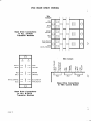
Referto the VSCControlBoardLayouton page5 for the locationof eachof theseconnectors
board.
at the end of the
you to checka modulereferto the CheckingProcedures
Wherethe procedureinstructs
symptomssection.
at the end of this
Procedures
to replacea module,referto the ModuleReplacement
Whenit is necessary
manual.
page 4
)
VSC Control Board Layout
-
tr====l
cNlA
lo o
ffiu-;;-um
'tu
I
6
o - l
6 '1" o
I
I
I
I
I
I
I
I
I
B
tr====f
cNlE lo o
CNIF
o ol
166-6-d-6-o-ltJ_ _ _ _EJ 166'E-6-o-61
1
1
6
brt
6
(J
CN1B
o ol
I
I
a
I _ _ _ l
vsc r-----rr---rvAc
ASSY 80859I--l
o
Fl'
u
D
PLI
tr===f
PLT
tr==f
f 6 ' ! - o - - p - 6 - E - E - Et l. . . . t
n-.-.---\-l!----!:L___J
ll
I I
EoEE-o-EE-tl
CN5 E=l
DTn
l K l
PI.C
PLP
tr=f tr===l
n
l . . l
t]{i trI
u?Ei_
-"
PLTST
PLE
PLB
tr=f, tr==l
I. o ol lo ol lo
ol lo ol lo o q ol
L___r L_J L__-J L_J L___J
-
lfoj-!-o-tdlcN4
o
\R1J
cN3 |6-l
PLF E]
lyYrc LljJ
2 (+)
E
P]
@@@
1 (-)
I ZERO
50 00
f.-n
LK5
a
r
tol
lol
lol
t.l
ACCS- ECEL
Lo{t
ul|t
TTTTTTTIIo
o
@@@@@@@@@
Irl2pl1l0l6l7Fl
FII/D
REV
stB
EN
oooF=
yAX
lfEE
IJX
sFEs
stA
TCCEL rCE
rstE
llrE
ST RT ....
v/nz
aoGT
Flt X
cqap
SJP
cqP
I
uytr
cNzfl
flt]-I]-Tn
r
I lzlrlrlolclzlrl
l o d o o o o o o l
l:l
tol
l"l
t9t
cN1
Pts
EF
IEEE-E-E-E-E-EI
TI----\l
l o E o o o o g E l
UV
OV
OT
@
Z Z
e (7
rv
Y)
<)
@ .v
a e (,) e Z
.>
V)
Z
eeo
Location Key
Component Networks
F7
cN2 trO
cN3 E1
cN4 D6
cN5 D5
CN1
CNlA
cNlB
cNlC
cNlD
CNlE
cNlF
41
A2
A3
A4
A5
A7
Links
LK1
tK2
LK3
LK4
LK5
D5
n6
nq
E4
Conn ectors
PLB
PLC
PLD
PLE
PLF
PLI
PLL
D7
D7
D5
D7
E2
D6
G2
PLP
PLS
PLT
PLU
PLV
PLW
PLTST
D8
C7
D6
A2
A4
A6
D2
S w i t c he s
Trimpots
SWA FJ
SWB n z
VR 0
VR 1
VR 2
VR 3
VR 4
E
E
E
E
A
4
+
4
6
8
V S C S E T UP FOR SERVICING
For easeof servicingwe recommend
that you reconnect
the controlcircuitryto the minimum
requiredfor VSCoperation.
Thefollowing
connections
are recommended:
VSC Gontrol Board
1
2
3
4
5
6
7
I
I
10
11 12
13
14
15
16
17
18
)
to Stort
Start./Stop Swltch
155 ohm to 5000 ohm
Spccd Control Potcntlomctcr
In eachstepof the serviceprocedure
willappeara "statusLine"as shownberow:
PowerSupplyOtf
VSCStopped Speed:0%
It is importantthat you observethis line carefullythroughoutthe procedureto obtainthe correct
resultat eachstep.
PowerSupplyOff
MainsAC supplyis NOTconnected
to L1,L2,L3.
PowerSupplyOn
MainsAC supplylSconnected
to L'l,L2,L3.
VSCStopped
Start/Stop
switchis OPEN.
VSCStarted
StarVStop
switchis CLOSED.
Speed:0%to 100% Setting
of speedcontrolpotentiometer.
Oo/o=zeto
speed,PotCounterClockwise
100%:fullspeed,PotClockwise
lf it is not possibleto connectthe VSCas shownaboveyou mustdetermine
howbestto useyour
controlcircuitto achievethe aboveconditions.
page 6
)
VSC MODULELOCATIONS
CHASSIS A
VSC Ghaegls Typc
VSC ltlodule Key
rl-------h
LL_i__!
t--;l
1
2
J
4
5
6
7
8
9
G H A S S T SB
nEfT-t-t
l'll'l'l'l
l
l
l
l
C H A S S T SD
nnn
l
l
Hlgh Performoncc
Gcnorol PurDosc
Slngle Phose
VSC_H3
VSC_H4
VSC-Hs
VSC-HIO
VSC_H13
VSC_H'I7
VSC_H24
VSC-G13
VSC-G17
VSC_G24
VSC_G32
A
B
B
B
VSC-S3 A
VSC-54 A
VSC-55 A
A
A
A
A
A
B
B
vsc-G38 c
vsc-H32 c
vsc-H38 D
VSC_G44 D
vsc-G60
D
VSC_H44 D
G H A S S T SC
EEE
l-71l '-------l
-
l z l
l
l
DIRECTCURRENTCURRENTTRANSFORMER
NOTE:There ore o number
of different types of DCCT.
They ore not interchongeoble.
8
l
MODULE
TRANSISTOR
BRIDGERECTIFIER
FAN
TRANSFORMER
TERMINALS
MODULE
CAPACITOR
IEMPERATURE
SENSOR
SNUBBER
BOARD
OUTPUTCHOKES
l
l
l
r---=-l
r/ rl----l
L1
EARTH LEAKAGE CURRENTTRANSFORMER
NOTE: There ore o number
of different types of ELCT.
They ore not interchongeoble.
r_-_ I
l " l
OverVoltageTrip at Endof ResetPeriod
PowerSupplyOn
VSCStopped
Speed:0%
Measurethe InputVoltageand check that it is within+10% to -15"/oof the nameplatevoltage.
M e a s u r et h e D C B u s sv o l t a g eb e t w e e n1 / P L B( - ) a n d 3 / P L B( + ) . l t s h o u l db e l . 4 x l n p u t v o l t a g e .
lf it is higherthanthisthenelectricalnoisemay be presenton the AC mains.Seethe sectionbelow
regardingelectricalnoise.
lf the DC Bussvoltageis correct,measurebetweenI1PLPand 3/PLP.You shouldget 30 Vac+3
Vac. lf not, check the controltransformer
and it's wiringfor damageand replaceit if necessary.
lf the voltageat PLPis correct,replacethe ControlBoard.Referto the ControlBoardReplacement
Procedure.
OverVoltageTripWhenZSP LED GoesOut
PowerSupplyOff
VSCStopped
Speed:0%
LocatetheCapacitor
Module(s)
andtherelay(s)
on them.TurntheAC PowerSupplyon andcheck
thatALL the relaysenergizeapproximately
1 secondafterpoweris applied.lf anyof the relays
do notenergizereplacethe Capacitor
moduleimmediately
or furtherdamagemayresult.
Checkeachcapacitormodule.Replaceas necessarv.
)
IntermittentOver VoltageTripping
PowerSupplyOn
VSCStopped
Speed:0%
Intermittent
OV trippingcouldbe causedby oneof twothings.Eitherthereis an intermittent
fault
in the ControlBoardor thereis electrical
noiseon the mainpowersupply.The latteris most
commonand can usuallybe verifiedby observing
the DecelLimitLEDon thecontrolboardwith
the VSCpoweredup but notoperating.
lf the DecelLimitLEDflashesoccasionally,
and theseflashescorrespond
to OVtrips,thenthere
is probablyelectrical
noiseon theAC mainspowersupply.
ElectricalNoise
Thereis no simplesolution
forelectrical
noiseproblems.
Thebestapproach
is to analyse
thenoise
for typicalamplitude
and duration
characteristics,
thendesignan appropriate
filterto removethe
noise.lf you thinkyou havea noiseproblempleasecontactour salespersonnel
to discussthe
problem,
bestsolution
for yourparticular
Over CurrentPlus or Over CurrentMinus at End of Reset Period
PowerSupplyOn
VSCStopped
Speed:0%
Wheneverthe transistordriversare disabled,no currentcan flow, thereforethe fault lies in the
controlboardor the DCCT.Removethe plug fromconnectorPLl.Measurebetween1/PLl(+) and
3/PLl (-) on the controlboard,it shouldbe 12 Vdc+O.1Vdc. lf not replacethe controlboard.lf
OK, insertthe plug back intoconnectorPLl.Measurethe voltagebetween2lPLl(+) and 3/PLl(-)
it shouldbe 6 Vdc+0.5 Vdc. lf not, replacethe DCCT.
Measurebetween2/CN4(+) and 3/CN4(-) on the dc millivoltsrange.lt shouldbe 0.0 Vdc+300
mV. lf it is outsidethis range,adjustVRl3on the controlboard untilthe meterreads0.0 Vdc+30
mV. lf you cannotachievethis, replacethe DCCT.
lf the VSC stilltrips on OC+ or OC- at the end of the resetperiod,replacethe ControlBoard.
page I
)
c
OverCurrentPlusor OverCurrentMinuswhenZSP LEDGoesOut
PowerSupplyOff
VSCStopped
Speed:0%
Checkthe PowerTransistors.
lf one or moreis faulty,replacethe transistor
module(s)as necessary.
Checkthe BaseDriveCircuits.lf any of the six circuitsdo not operateproperly,replacethe control
board BEFOREproceedingany furtheror transistordamagemay result.
PowerSupplyOn
VSCStopped
Soeed:0%
Removethe plug from connectorPLl. Measurebetween1/PLl(+) and 3/PLl (-) on the control
board,it shouldbe 12 Vdc+0.1 Vdc. lf not replacethe controlboard.lf OK, insertthe plug back
into connectorPLl, Measurethe voltagebetweenzlPLl (+) and 3/PLl(-) it shouldbe 6 Vdc+0.5
Vdc. lf not, replacethe DCCT.
Measurebetween2lCN4(+) and 3/CN4(-) on the dc millivoltsrange.lt shouldbe 0.0 Vdc+300
mV. lf it is outsidethis range,adjustVRl3on the controlboard untilthe meterreads0.0 Vdc+30
mV. lf you cannotachievethis, replacethe DCCT.
lf the VSC stilltrips on OC+ or OC- when the ZSP led goes out, replacethe ControlBoard.
EarthFaultTrip
PowerSupplyOff
VSCStopped
Speed:0%
Inspectthe ELCTfor physicaldamage.Removethe plug from PLEand measurebetween1/PLE
and 2/PLEon the plug with a multimeter
on ohms range.lt shou.ldbe a shortcircuit.lf not,replace
the SensorWiring.lf the ELCTis OK, plug it back into PLE.
lf your model VSC has output chokes (referto the InternalWiringdiagrams)removethe choke
wiresfrom the TransistorModules.Use an Insulation
Tester(500V) to check betweeneach of the
outputterminals(Ml, M2, M3) and the Earthterminal.Replaceany chokeconnectedto an output
terminalwhich is less than 50 kohmsto Earth.
lf the VSC stilltrips on EarthFault,replacethe ControlBoard.
UnderVoltageTrip
PowerSupplyOn
VSCStopped
Speed:0%
Measurebetween1/PLPand21PLP
on the controlboard.You shouldread 15Vac+2Vac. Measure
between3PLPand ZPLP.Againyou shouldget '15Vac+2 Vac. lf not,checkthe controltransformer
for damageand replaceas necessary
Measurebetween1/CN4and 3/CN4for a voltagebetween4.18Vdc and 6.88Vdc. lf this voltage
i s l e s st h a n4 . 1 8V d c , c h e c kt h e w i r i n gb e t w e e nt h e D C B u s sa n d c o n n e c t oP
r L B ,a l s oc h e c kt h e
B r i d g eR e c t i f i eM
r odule.
lf the voltageat CN4 is correct,replacethe ControlBoard.
Checkthe BridgeRectifierModule.Referto the CheckingBridgeRectifiersection.
Checkthe CapacitorModule(s)as describedin the CheckingCapacitorModulesection.
TriP
OverTemperature
is notblockedwithany
properly
andthattheheatsink
is operating
Checkthatthefan (if installed)
and check
grills
for
blockages
and
filters
all
chect<
matter.lf th; vSC iJ in an bnclosu"re,
t,creign
fan(s)(iffitted)areoperating.
thatthe enclosure
PowerSupplyOff
VSCStopped
Speed:0%
Measurethe temperatureof the heatsink(by touch if you do not have a thermometer)
Soeed=0%
VSCStopped
PowerSupplyOn
Measurebetween1/PLT(+) and 2PLf (-). The voltageshouldbe:
"C)x10mVt5%
V : ( 2 7 3 + H e a t s i n kT e m P
lf you do not obtainthis, replacethe SensorWiring'
PLT is less
The temperaturetnp point is 3.52 Vdc which correspondsto 80"C, lf the voltageat
board.
the
control
replace
than 3.52 Vdc and tne Of LED illuminates
PowerLED DoesNot llluminate
PowerSupplyOn
VSCStopped
Speed:0%
Measurebetween1/plp and 2/pLPon the controlboardfor 15 vac't2 Vac.Measurebetween
3/pLp and2lpLPfor 15 Yac+2Vac.lf not replacethe controltransformer.
Speed:0%
VSC Stopped
PowerSupplyOff
)
lf the voltageat PLP is OK then removethe plug from connectorPLI'
illuminate'
lf the power On LED iluminates,replacethe DCCT.lf the PowerOn LED stillfails to
replacethe ControlBoard.
of lnputPower
FusesBlowOn Application
Checkthe BridgeRectifierand replaceif necessa;y'
Checkthe TransistorModule(s)and replaceif necessary'
checkthe controlboardbasedrivecircuits.
module(s)then
lf thereis any damageto the transistor
Checkthe CapacitorModule(s)and replaceif necessary'
Soeed:0%
VSCStopped
PowerSupplyOff
Testerto checkbetweenthe control
Removethe plug from connectorPLP.Use an Insulation
if thewindingis lessthan
transformer
the
control
primary*indingand Earth.Replace
transformer
Earth.lf thetransformer
and
winding
secondary
the
soo k ohmsto Earth.Repeitthetestbetween
PLP'
is OK, plugit backintoconnector
Motor Phase Voltageor Currentlmbalance
and replaceif necessary.
for an opencircuittransistor
Module(s)
checktheTransistor
and replaceif necessary
Checkthe ControlBoardBaseDriveCircuits
replacethe control
or the basedrivecircuits,
module(s)
lf no faultis foundin eitherthe transistor
board.
Motor lnstabilitY
c hec k
module,
if ,ther eis m or ethanoneCapacitor
In p a r ticular
r d u l e (s).
C h e c kt h eC a p a ci toMo
not
damaged.
are
tf,"i tn" wiring'toaltthe modulesis intactand thatoneor morecapacitors
page10
)
c
AccelLimit(CurrentLimit)CircuitActivatesToo Early
PowerSupplyOff
VSCStopped
Speed:0%
VSCStopped
Soeed:0%
Inspectthe DCCTfor physicaldamage.
PowerSupplyOn
Removethe plug from connectorPLl. Measurebetween1/PLl(+) and 3/PLl (-) on the control
b o a r d ,i t s h o u l db e 1 2 V d c + 0 , 1V d c . l f n o t ,r e p l a c e t h ec o n t r o b
l o a r d .l f O K , i n s e r t t h ep l u g b a c k
intoconnectorPLl.Measurethe voltagebetweenzlPLl (+) and 3/PLl(-), it shouldbe 6 Vdc+0.5
Vdc, lf not, replacethe DCCT.
Measurebetween2lCN4(+) and 3/CN4(-) on the dc millivoltsrange.lt shouldbe 0.0 Vdc+300
mV. lf it is outsidethis range,adjustVRl3on the controlboarduntilthe meterreads. Vdc+30 mV.
lf you cannotachievethis,replacethe DCCT.
C h e c kt h eC a p a c i t oM
r o d u l e ( s )l f.t h e r ei s m o r et h a no n e m o d u l ec h e c kt h ew i r i n gt o a l lm o d u l e s .
lf the DCCTand the CapacitorModule(s)are OK then replacethe ControlBoard.
The followinglistof symptomsindicatea ControlBoardFailure
0
EnabledLEDdoesnotilluminate
whentheVSCis enabled.
Direction
LEDdoesnotilluminate
whena direction
is selected.
Enabled/Direction
ledsilluminate
butVSCwillnotstart.
SpeedReference
selector
doesnotfunction.
RemoteTripled staysilluminated
whenterminals
5 and 6 are bridged.
SpeedReference
inputsdo notwork.
SpeedOutputdoesnotwork.
LoadOutoutdoesnotwork.
ControlBoardrelaydoesnotfunctionproperly.
MODULES
THETRANSISTOR
CHECKING
"Six-Pack"Modulesand "Two-Pack"
The TransistorModulescome in two differentpackages,
"Six-Pack"Modulescontainsix powertransistors,
and so only one is requiredto make
Modules.
"Two-Pack"Modulescontaintwo power transistors,
and so
up the three phase inverterbridge.
threeare requiredto make up the three phaseinverterbridge.
"diode test" range.This range
To check transistormodulesyou will requirea multimeterwith a
junction.You will also need to be
measuresthe forwardbiasedvoltagedrop of a semiconductor
range.
1
000
Ohms
the
100
to
resistance
on
able to measure
"Red"and "Black"leadsof the
Forthe diode testson the transistormodules,we havedefinedthe
multimeteras describedbelow.
"RedLead"
currentor positivelead
Sourceof conventional
"BlackLead"
currentor negativelead
Sinkof conventional
TestingSix-PackModules
PowerSupplyOff
VSCStopped
Speed:O%
moduleandthenremoveallthewiringfromit.Set
to thetransistor
notetheconnections
Carefully
shownin the
eachof theterminals
between
range,and measure
to the appropriate
the multimeter
modulemustbe replaced.
tablebelow.lf theresultof eachtestis notasshown,thenthetransistor
to DiodeTestRange.
Setthe multimeter
Result
Required
BlackLead
RedLead
Op enCir cuit
N
P
( 2diodedr oPs)
0 .4to 1.0Vdc
P
N
Op enCir cuit
P
U .V .W
( 1diodedr oP)
0 2 0to 0,50Vdc
U,V ,W
N
( 1diodedr oP)
0 .2 0to 0.50Vdc
P
U, V, W
Op enCir cuit
N
U, V, W
OpenCircuit
BuP,BvP,BwP
P
Op enCir cuit
Bu N
U
OpenCircuit
BvN
V
OpenCircuit
W
BwN
to OhmsRange(100to 1 000Ohms)
Setthe multimeter
300to 800ohms
EuP
BuP
300to 800ohms
EvP
BvP
300to 800ohms
EwP
BwP
300to 800ohms
EuN
BuN
300to 800ohms
EvN
BvN
300to 800ohms
EwN
BwN
lf the modulepassesthistest,replaceall the wiring.Referto the VSCBaseWiringdiagramfor
detailsof the baseconnections.
page 12
)
)
c
TestingTwo-PackModules
PowerSupplyOff
VSCStopped
Speed:0%
Carefullynote the connectionsto the three transistormodulesand then removeall wiring from
each one. For each transistormodule,set the multimeterto the appropriaterange,and measure
betweeneach of the terminalsshownin the table below.lf the resultof each test is not as shown,
then the transistormodulemust be replaced.
Set the multimeterto the DiodeTest Range.
@
RedLead
C1
E2
C1
C 2 E1
E2
C2E1
C1
C 2 E1
BlackLead
E2
C1
C2E1
Cl
C2E1
E2
81
82
R esult
OpenCir cuit
0 .80to 1.00Vdc
OpenCircuit
0 20to 0.50Vdc
0.20to 0.50Vdc
OpenCircuit
OpenCircuit
OpenCir cuit
( 2 d i o d ed r o p s )
( 1 d i o d ed r o p )
( 1 d i o d ed r o p )
Setthe multimeter
to the Ohmsrange(100to 1 000Ohms).
B1
82
E1
E2
50to 800ohms
50to 800ohms
lf the modulepassesthis test, replaceall the wiring.Referto the VSC Base Wiringdiagramfor
detailsof the base connections.
Checkingthe BridgeRectifierModule
Forthediodetestson the bridgerectifier
modules,
we havedefinedthe "Red"and "Black"leads
of the multimeter
as describedbelow.
0
"RedLead"
"BlackLead"
Sourceof conventional
current
or oositive
lead
Sinkof conventional
current
lead
or negative
PowerSupplyOff
VSCStopped
Speed:0%
Notethe connectionsto bridge rectifiermodule,then removeall wiringfrom it. Set the multimeter
to the diode test rangeand measurebetweeneach of the terminalsshownin the table below.lf
the resultof each test is not as shown,then the bridge rectifiermodulemust be replaced.lf the
modulepassesthe test, replaceall the wiring.
RedLead
+ (KM+)
- (-AM)
+ (KM+)
AC1A
, C2A
, C3
- ( - AM )
A C 1 ,A C 2 A
, C3
0
BlackLead
- (-AM)
+ ( K M +)
A C 1A
, C2A
, C3
+ (KM+)
AC1A
, C 2A
, C3
- (-AM)
Result
OpenCir cuit
0.60to 1.2Vdc
OpenCircuit
0.30to 0.60Vdc
0 30to 0.60Vdc
OpenCir cuit
(2 diodedrops)
( 1 d i o d ed r o p )
( 1 d i o d ed r o p )
VSC BASE DRIVE WIRING
Wlre
Colours
PINK
YELLOW
WHITE
VIOLET
BROWN
ORANGE
Base Drive Connections
t o A L L 2 -P A C K
Transistor Modules
GREY
RED
BLUE/BLACK
PrNK/BLACK
D
BLUE
wHrrE/oRANGE
N
Wlre Coloure
P
E
U
t l
- l
B o
PINK
ts -
YELLOW
RED : B
GREY
Y
e-
BROWN
e B
wHrTE/ORANGE
BLUE : E
H
IUI
VIOLET : B
WHITE E L
t
il
t l
c
=
!
;-ss >
=;e=,nE
aE=E=;
ORANGE
B :
BLUE/BLACK
E :
PrNK/BLACK
D
Baee Drive Connectlons
to VSC Control Board
Base Drive Connections
to ALL 6-PACK
Transistor Modules
\
4
page 14
c
Checking the Base Drive Circuits
To check the bose drive circuits on the control
boord, you will require on omrneter copoble of
meosuring 500 mA DC, ond o 1 omp, 100 V
rectifier diode. (1N4001 or equivolent.)
Connect the Positive Bose Current Meosurino
circuit to 1/PLU ond 2/PLU os shown belori.
There ore six bose drive circuits on the control
boord, two connected to eoch of the three
sockets, PLU, PLV ond PLW os shown below.
C h e c k t h o t t h e m e o s u r e d c u r r e n t c o r r e s o o n d st o
the volue shown in the toble for your VSC model.
Positive Base Current
Power Supply
Crrrrent
Measrrrcmcnt
Negative Base Current
Proaadrrre
Power Supply Oll, VSC Stopped, Speed :
100%
Check
Power Supply Olf, VSC Stopped, Speed :
0%
0%
Connect the Negotive Bose Current Meosuring
circuit to 1/PLU ond 2/PLU os shown below.
Check thot the copocitor module(s) ore fully
dischorgedby corefullymeosuring between the
olus ond minus terminols on eoch module. DO
NOT do ony work inside the VSC until this
voltoge is below 24 Ydc.
0
Speed :
Power Supply Off, VSC Stopped, Speed : 0%
Repeot this procedure for the other five bose
drive circuits os shown below.
To check eoch bose drive circuit, the positive
bose current ond the negotive bose current ore
m e o s u r e d s e p e r o t e l y .T h i s i s o c h i e v e d b y p l o c i n g
the diode in series with the ommeter.
Base
On, VSC Started,
Check
Power Supply On, VSC Started,
Speed :
100%
C h e c k t h o t t h e m e o s u r e d c u r r e n t c o r r e s p o n d st o
the volue shown in the toble for your VSC model.
Remove the three connectors, PLU, PLV ond PLW
from their sockets ond ploce them where they
connot touch ony live wires, the control boord or
the chossis.
Power Supply Ofl, VSC Stopped, Speed :
0%
Reoeot this orocedure for the other five bose
drive circuits os shown below.
If any one of the six base drive circuits fails to meet either the Positive OR negative
currents required, then the Control Board MUST be replaced or further damage may result.
Positive Base
Current Measurement
VSC-H3:
44 to 66 mA
VSC-H4:
44 to 66 mA
VSC-HS:
44 to 66 mA
VSC-HIO: E4 to 126 mA
VSC-H15: 120 io 180 mA
VSC-H17: 120 to 180 mA
VSC-H24: 120 to 180 mA
VSC-H32: 156 to 234 mA
VSC-HJE: 204 to 308 mA
VSC-H44: 204 to 306 mA
IVSC-G15: E 4 t o
lVSCrGlT:
20 to
I VSC-G24: 2 0 t o
I VSC-G32: 2 0 t o
I V S C - G S 8 : 56 to
I V S C - G 4 4 : 58 to
I V S C - G 6 0 : 204 to
+-
i -
tr====l
0
-
o ol
-QJ
PLU
l..1
v
l
l o
o
o
tr====l
o l
Ll----fu
"
11
I
Negative Base
Current Measurement
t D D
o
PLv
I
I
O
VSC-H3:
31 lo 47 mA
VSC-H4:
31 to 47 mA
VSC-HS:
31 to 47 mA
VSC-H1O: 52 lo 78 mA
VSC-Hl3:
64 to 96 mA
VSC-H17:
64 to 96 mA
VSC-H24:
64 to 96 mA
VSC-H32: 76 to 114 mA
VSC-H38: 84 to 126 mA
VSC-H44: 84 to 126 mA
n
o
o
o l
t o
Ll- - - -5J
,0
/1
\
-
PLU
r
I
I
,
o
o
n
OPLV
I
I
PLIT
I
o
, t J -J+J
o l
Ll- - - -iJ
v
O l
52 to 78
I VSC-G1S:
IVSC-G17:
64 to 96
I VSC-G24:
64 to 96
I VSC-G52:
64 to 96
V
S
C
G
5
8
:
7
6 to 114
I
I VSC-G44: 76 to 114
I VSC-G6O: 84 to 126
tl
l E
O
Ll- - - -iJ
J- +' ' -,t+,l,
I
m A VSC-S5: 61 to 93 mA
m A VSC-S4: 61 to 93 mA
m A VSC-S5: 6 1 i o 9 3 m A
mA
mA
mA
mA
't'' ,t,l
'i,'i, J J
lo "
L1- -
126
160
180
180
234
234
306
O
.r^\
LJ
o ol
l. .
Ll- - - -iJ
PLW
I
I
.,^l
LJ
mA I VSC-S5: 3l to 47 mA
mA IVSC-S4: J1 to 47 mA
mA I VSC-S5: J1 to 47 mA
mA
mA
mA
mA
C H E C K IN GT HE CAPACITORMODULES
fromthe chassis,checkthatthe relaydrivercircuitis
the capacitormodule(s)
Beforeremoving
procedure
properly
below.
the
by
following
functioning
PowerSupplyOff
VSCStopped
/1-
Speed:0%
Make sure the small plug-inconnectoris securedin its socketon each of the modules.Check
that all wiringto each moduleis properlyconnected.
1
Observethe large relay(s)on the moduleas you apply input powerto the VSC.Approximately
secondafterapplicationof inputpowerthe relay(s)shouldenergizeand stayenergizeduntilinput
poweris removed.lf the relay(s)do not energizeor if theytake longerthan2 secondsto energize,
thenthe moduleis notfunctioningproperlyand mustbe replacedbeforeproceedingany further.
Warning- lf the capacitormodule'sdischargecircuithas failed,it may take severalminutesfor
the voltageto dischargeto a safe level.
lf the relaysenergizeproperly,removepowerfrom the VSC and observethe neon indicatoron
the capacitormodule.Timethe periodbetweenturningthe poweroff and the neon going out. lf
it is longerthan60 secondsthenthe dischargecircuithasfailedand the modulemustbe replaced.
Carefullymeasurebetweenthe plus (+) and minus(-) terminalson the capacitormodulewith a
multimeteron 1 000 Vdc range.Wait untilthis voltageis below 24 Ydc beforedoing any work
insidethe VSC.
\
u
Warning- lf there is more than one capacitormodulein the VSC, measurethe voltageon each
one to be sure that they have all dischargedbeforedoing any work insidethe VSC.
Disconnectthe powersupplyfrom the VSC inputterminals.
Locate the wires connectingthe capacitormoduleto the transistormodule(s).Make a note of
whereeach wire connectsto the transistormoduleso thatyou can replaceit properly.Disconnect
the wiresat the transistormoduleend, leavingthem connectedto the capacitormodule.
lf the Capacitormoduleis mountedto the bottomof the chassisremovethe four flangenutsand
carefullyliftthe modulefromthe studs.lf the moduleis mountedon the side of the chassis,remove
the four screwsfrom the outsideof the chassiswhilesupportingthe moduleon the inside.
Removethe capacitormodulefrom the chassis,completewith wiring,and check the following:
Inspectthe body of eachcapacitorfor physicaldamagesuchas dents,smallholes,bubbles
the top) or any sign of excessiveheat (meltedplastic
in the aluminiumcase (particularly
oin
\
\
4
Checkthe undersideof the PCB for damagesuch as brokentracks,scorching,excessive
h e a t i n gd, r y ( c o l d )s o l d e rj o i n t so r a r c i n g .
Checkthe relaycontactsfor signsof arcingpittingor excessiveheating.
"push-on"connectorson each wire are firmlyconnectedto the module.
Checkthat the
lf any physicaldamage is observed,the entirecapacitormodule,includingwiring,should be
reolaced.
Check
CapacitorModuleMultimeter
Thereare threedifferentPCB's.Checkthe undersideof the capacitormodule,and locatethe part
code.Choosethe appropriateprocedure
code and a seven-character
number.Thisis a three-letter
perform
the multimetertestson vour module.
belowto
\
page 16
AF Y ( 8 0 8 3 1 9 08, 0 8 3 1 1 2 ,8 0 8 3 1 60)
ia
e
Thisis a two or four-capacitor
moduleusedin VSC-Gand VSC-Hmodels.
(120ohmASWSor '150ohmASWS).
Locatethetwoblacktubularpowerresistors
Measure
across
e a c ho n eo n o h msra n g efo r 1 1 0to 1 60ohms.
Setthe multimeter
to the 30 kohmor 50 kohmrange.
Arrangethewiresso thattheycannottoucheachotheror the PCB.
Measurebetweenthe + (plus)push-onterminaland the - (minus)push-onterminalon the
capacitormodule.The metershouldstartfromzeroohmsand slowlyincreaseto full scalein
approximately
20 seconds.Reverse
the meterleads.Themetershouldgo fromminusfullscale
to zeroand thenincrease
to fullscaleagainin approximately
30 seconds.
Thechargingtimesand resistances
givenabovemayvarydepending
uponthe meterused.The
important
thingis thatthecapacitors
should"chargeup" (theresistance
increases)
and,whenthe
leadsare reversed,
(theresistance
theyshould"discharge
and thenre-charge"
appearsto go
negative,
dropto zeroand increase
again).
lf the modulefailseitherof thesetwotestsit mustbe reolaced.
AFZ (8083290,8083212,8083260)
This is a six or eight-capacitor
moduleused in VSC-Gand VSC-Hmodels,
Locatethe four blacktubularpowerresistors(120ohm ASWSor 150 ohm ASWS).Measureacross
each one on ohms rangefor 65 to 80 ohms.
Set the multimeterto the 30 kohm or 50 kohm range.
Arrangethe wiresso that they cannottouch each otheror the PCB.
Measurebetweenthe + (plus) push-onterminaland the - (minus)push-onterminalon the
capacitormodule.The metershouldstartfrom zeroohms and slowlyincreaseto about20 kohms
in approximately
60 seconds.Reversethe meterleads.The metershouldgo from minus20 kohms
to zero and then increaseto 20 kohmsagain in approximately
60 seconds.
The chargingtimesand resistances
given abovemay vary dependingupon the meterused.The
importantthing is thatthe capacitorsshould"chargeup" (the resistanceincreases)and, whenthe
leads are reversed,they should "dischargeand then re-charge"(the resistanceappearsto go
negative,drop to zero and increaseagain).
0
lf the modulefailseitherof thesetwo testsit must be reolaced.
0
page17
AGH (8084090,8084012,8084060,8084061)
moduleusedin theVSC-Smodel.
Thisis a two,threeor four-capacitor
(120ohmASWSor 150ohmASWS).
Measure
acrossit on
Locatethe blacktubularpowerresistor
o h m sr a n g ef o r 11 0 to 1 6 0o h ms.
Setthe multimeter
to the 30 kohmor 50 kohmrange.
Arrangethewiresso thattheycannottoucheachotheror the PCB.
Measurebetweenthe + (plus)push-onterminaland the - (minus)push-onterminalon the
to about20 kohms
capacitormodule.Themetershouldstartfromzeroohmsandslowlyincrease
go
from
minus20 kohms
meter
leads.
The
meter
in approximately
Reverse
the
should
90 seconds.
90 seconds.
to zeroand thenincrease
to 20 kohmsagainin approximately
givenabovemayvarydepending
uponthe meterused.The
Thechargingtimesand resistances
"charge
(the
resistance
increases)
and,whenthe
up"
important
is
that
the
capacitors
should
thing
(theresistance
appearsto go
and then re-charge"
leadsare reversed,
theyshould"discharge
again).
negative,
dropto zeroand increase
lf the modulefailseitherof thesetwotestsit mustbe replaced.
CAPACITORMODULE REPLACEMENTPROCEDURE
A capacitor
moduleconsists
of the PCBANDthewireswhichconnectto it.Do notswapthewires
lf youhaveobtaineda newmodule,be sureto usethewiressuppliedwiththis
between
modules.
module.
fitit backon itsmounting
hardware
andre-connect
To replacetheCapacitor
Moduleinthechassis,
Replaceall the wiresEXACTLY
as they wereoriginally
the wiringto the transistor
module(s).
connected.
Checkthatthe relayis firmlypluggedintoits socket.
MODULE
CHECKALL WIRINGCAREFULLYBEFOREAPPLYINGINPUTPOWERORTRANSISTOR
DAMAGEMAYRESULT.
\\
a
\
a
PROCEDURE
VSCCONTROLBOARDREPLACEMENT
PowerSupplyOff
VSCStopped
Soeed:0%
Removeall the plugs from the old controlboard. Removeall the wiringfrom the terminalstrip.
(Make sure you can put it all back.)With a SMALLpair of pliers,carefullysqueezeeach of the
plasticstand-offs,gently liftingunder each one at the same time. When all the stand-offshave
been released,removethe old controlboard.
Locatethe ModelNumberand VoltageRatingof the new controlboardon the lefthandsideabout
150 mm from the front edge of the board (justabovethe large lC). Make sure it is the same as
the board you are replacing.
lf the model number and voltage rating are blank,you will have to set up the board for your
particularVSC model. There will be an instructionsheet and a packet of plug-incomponent
carefullyto set the boardup for your
networkssuppliedwiththe new board.Followthe instructions
VSC model.
makingsuretheyare all pokingthroughthe mountPlacethe new controlboardon the stand-offs,
ing holes.Gentlypush down aroundeach of the stand-offsso that they all pushthroughand lock
down over the board.Be carefulnot to bend any components.
Replaceall the plugs intotheirsockets.
Re-connectall the wiringto the terminalson the controlboard.
M.A K ES U R EN O N EO F T H E M
DR O P E R L Y
C H E C KT H A TA L LT H EP L U G SH A V EB E E NI N S E R T EP
A R ED I S P L A C E D
B Y O N EP I N
VSCStopped
Speed:0%
PowerSupplyOn
"l
LocateVR13, ze(o",a ten-turn
trimpot.Referto theVSCControlBoardLayoutfor its location.
page18
)<-
\
4/
/')
(
range.AdjustVRl3untilthemeterreads0.00
Measure
between2lCN4and3/CN4on DC millivolts
Vdc+30mVdc.(Note:lf measured
at another
timethisvoltagemaybe +300 mVdcdue to tempit.)
eraturedrift.Thisis nota problem,
andthereis no needto re-adjust
PowerSupplyOff
r
VSCStopped
Speed:0%
Thiscompletes
the installation
of the newcontrolboard.
't
DCCT REPLACEMENT
PROCEDURE
PowerSupplyOff
VSCStopped
Speed:0%
Locatethesmall1O{urnadjustment
trim-pot
on the DCCTand notewhichendof thewireor Buss
bar is adjacentto it. Removethe wireor Bussbar whichgoesthroughthe DCCT.Removethe
DCCTand replaceit withthe newoneso thatthe adjustment
trim-potis on the samesideof the
conductor
as withthe old DCCT.
c
PowerSupplyOn
VSCStopped
Speed:0%
LocateVR13,
a 1Oturntrimpot,"l zeto".Referto page5 for its location.
Measure
between
2/CN4and3/CN4on DC millivolts
range.AdjustVR13untilthemeterreads0.00
Vdc+300 mVdc.(Note:lf measuredat anothertime this voltagemay be +300 mVdc due to
temperature
drift.Thisis nota problem,
and thereis no needto re-adjust
it.)
PowerSupplyOff
VSCStopped
Speed:0%
Thiscompletes
the installation
of the newDCCT.
PROCEDURE
IN P U T R E C T IF IERREPLACEM ENT
PowerSupplyOff
@
VSCStopped
Speed:0%
Alsonotetheconnections
to
Notecarefully
the orientation
moduleon the heatsink.
of the rectifier
fromthe moduleand liftit fromthe heatsink.
the module.Remove
the mounting
screw(s)
greaseto thebaseof thenewmoduleand placeit on theheatsink
Applya lightsmearof heatsink
in the sameoosition
as theold module.
Replace
lf thewiresconnectto push-on
the mounting
and re-connect
thewirescarefully.
screw(s)
terminals,
makesuretheyall makea tightconnection.
PROCEDURE
TRANSISTOR
MODULEREPLACEMENT
PowerSupplyOff
0
VSCStopped
Speed:O%
to it. Paycareful
Beforeremovingthe old transistormodule,makea noteof all the connections
attention
to the connection
of the BaseDrivewires.
module.lf thereare threemodulesremovethe Bussbars
Removethe wiresfromthe transistor
from the transistors
WITHOUT
removingthe wiresconnecting
the Bussbars to the capacitor
modules.
Remove
and thenremovethe old module(s).
the mounting
screwsfromthe module(s),
greaseto the baseof the newmodule(s).
Applya thinsmearof heatsink
screws.Turnall the screwsup
Placethe newtransistor
and insertthe mounting
on the heatsink
DO
NOT
tighten
thescrewsor thetransistor
fingertight,andthenturnthemup a littleat a time.
over
modulemaycrack.
Replacethewiringand checkit carefully.
page19
I
L
SENSORWIRINGREPLACEMENT
PROCEDURE
r\\
PowerSupplyOff
VSCStopped
Speed:0%
TheSensorWiringconsists
of:
the Bussvoltagesensingwires- connector
PLB
- connector
thetemperature
sensor(LM355)
PLT
the ELCT- connector
PLE
lf anyoneof theseitemsneedsreplacing,
theSensor
Wiringshouldbe replaced.
Carefully
observe
the location,
mounting
andconnection
of theELCT,Temperature
Sensorand BussSensing
Wires.
Remove
theELCTby removing
thewireswhichpassthroughit andslidingit overtheendof them.
Remove
theTemperature
Sensorby removing
thescrewfromtheclampholdingit to the heatsink.
Remove
the Busssensingwires,notingcarefully
wheretheyconnect.
Unplugtheconnectors
PLE,
PLTand PLBfromthe controlboard.Nowthe old SensorWiringmaybe removed.
Fitthe newSensorWiringby slidingthe ELCToverthewireswhichpassedthroughtheold ELCT
and re-connecting
thosewires.PlacetheTemperature
Sensoron to the heatsink,
withtheflatside
facedown.Replace
theclampand screwit intoplace.Connect
the Busssensingwiresto the DC
buss.Plugconnectors
PLE,PLTand PLBintotheirsocketson the controlboard.
Thiscompletes
the replacement
of the SensorWiring.
ly'
1\,
a
'$1,
4l/
s\
page20
VSC-H lnternal Wiring Diagram
C
cE
t> 6 E = s g
g
ifr
o
&
c
o
Io
so
t
c
o
N
c
ir-\,f-
o
o
8
c
3
I
a 3
e I
L
G
s
g
o
3
N
c
6
o
I
o
B
8
t
c
I
o
q
I
t
Io
Io
t
G
t
IG
t
tr
o
o
c
I
E
n
e
do
d
8
o
c
4
G
d
N
F
F
t
o
o
g8 €
c
E
E
E
&
m
C)
9
ET
o
z
x
R
o
o
4
C
c
4
F
N
o
o
G
c
c
t
N
L
o
I5
6
o
c
o
c
F
F
5 It
t
N
L
d
F
c
N
o
t
t
t
N
d
3 8
N
d
t
I
o
o
4
o
N
N
I
8 I
G
t
8
G
e
ua
E9
et
Ert
t
3 I
t
&
c
G
o
g
o
4
A
F 8I
N
!
g
t
E
o
E8
3E
N
t
E
I
F
g3
c
c
o
a
q
o
F
N
G
R
o
6
8
o
8
F
c
t
t
d
o
o
I
$
:
A
F
N
4
G
o
&
G
F
E
t
L
D F
i t FE
o
F 5
G
t
I
I
HB i*
8
o
t
d
ts
t
i
I t$ g
8
8
c
t
5g
t
c
t
8
4
!a o
q
::
4
R
5
o
c
e
t
g 3
d
I
!g
ngt g
I
c
rF
E
o
N
4
4
g $ FE t
F
t
F
t
It I
t
3...
o
o
N
E
I
5
N
G
o
(J
g
L
N
o
5
6
d
o
o
o
I
4
I
o
=
n
E
8
o
t
I
t
A
E E t
o
F
o
o
EE
g e
N
o
o
g
E
I
9 atr
frl
A
o
G
5
E t E
E
o
o
cc
U)
I
8
o
G
d
t
c
o
4
4
4
6
F
d
t
o
{
N
G
o
o
o
o
o
ts
d
q
c
P
@
o
o
gE g g g
g
c
o
I
N
4
c
N
I
G
o
N
t
:
o
ri
cJ
5E
E F
tt
G A
N
F
N
o
c
E
G
G
a
(
,<
,c
{a
IH
i
5=
,l
I
I
o
I
I
9
E
I
EE
o
T
*
T
o
I
F
I
I
E
I
E8 g
?
E
I
d!
;t;ii:E;t
o
EE
d----rr'
Ei
H.iiilEii3;
=li;ii;::g:
page 21
VSC-G Internal Wiring Diagram
t),
o
o
o
o
o
c
o
o
8
I
N
I
I
t
to
ir
;o
Its
i@
io
tz
i<
iF
r9
a
F
E
o
o
@
o
6
N
A
c
4
c
c
o
I
P
6
c
d
o
ts
e
I
o
E
c
4
N
F
o
8
5
d
5
o
o
d
F
F
c
€
c
oE
=F
@
=i
d:
E
c
o
c
rrl
tr
8
c
o
d
F
@
8
d
n
6
8
o
oc
EC
e
G
o
c
irq
ts
A
$
c
E
o
I
c
so
o
F
$-,I
I
L
o
e
o
d
a
d
m
F]
m
E
t@,0
6
@
o
o
o<
Q
ZE
E
e
c
I
c
d
8
e
o
@
o
frz
6S
-l
Fl
z
trl
ts
d
I
c;
c
o
I
t: q
I
8
s E
3
!
:t
I
ii
c
e
a
c
c
4
E
o
I
c
c
o
o
I
24
o
o
I
o
e
c
c
-i
t:
t
4
F
q
I
ra
c
N 6
c
6 6 6
*
4
q
d
4
o
o
o
e
c
I
o
9
r
o
o
9
o
9
o
o
9
B
E
I
o
9
o
I
I
irtsjif;'
irlii
page 22
d
E
dt
LE
EE
g
L d
t( a;
<!
lJz
o
o
o 4
N
q
Io
c
I
I
o
o
o
d
E
z
fu
N
o
I
d
lr--ll'
u
6l
8J
=
d
z
l
a
l
4
i
z
s=t;;ltiir;
IE;i
!;i:5i
f.
14
VSC-S Internal Wiring Diagram
C
l
.6=
F".F
o
- Uz IuI
I
I
I
I
8
o
o
i
o
o
o
o
E
f
I
I
c
i
rH
dEI
a2t
' iroO
: I
-
c
t
68
g
E
I
I
FI
I
vt
6
x.
yt
H-
J
m
()
m
trl
rrl
v)
tr
F
z
A
FI
o
2
()
m
r
o6
EE
i!a
tz
t<
i
I
4
t
rE
IP
;F
8
o
q
a
F
d
d
o
z
s
lq
iB
?:
o
5
c
o
d
o
o
o
E
L
N
d
N
o
c
4
o
E
o
FE E
{
o
o
d
5* g
I
8
o
a
o
4
t
o
o
4
o
o
o
o
o
o
o
A
3e
o
t
t
rE
:b
t
I
I
o
o
o
c
o
=*
ct
ci
t
;i
,q
<@
5:
rl
@
r l
J
/,_--'.-\
-
N
n
*
9
6
I
$
o
I
,isi;ii
gl
.
I
o
\
tr
r'l
=
,-t =
E5
zz
5 ! ; ge ; i
;eg:
!;!
()<
E
{J----rr'
6l
6L
o
page 23
VSC Voltage Selection Procedure
"ACXXXX3",
"MULTI
This procedure is only opplicoble to
VoLTAGE" VSC's. These VSC's hove o Port Number
"XXXX"
where the
stonds for ony combinotion of digits. Any VSC with o Port Number thot does not end
with 3 con not hove it's input voltoge chonged. You should hove been supplied with o pocket contoining
4 smoll plug in links ond o sheet of self odhesive lobels. Follow the three steps below to select the
input voltoge you require.
1. TranslormerTapplngSelectlon
-
Remove the AC Power Supply from the VSC. Ensure the
filter copocitors ore fully dischorged,Loosen the screw in
the lid of the VSC ond open the lid. Locote the control
tronsformer just obove the Power Input/Motor Output
terminols. On the top of the tronsformer is o printed
circuit boord with the voltoge selection toppings. A drowing
of this boord is shown opposlte, Removethe topping corefully
ond reploce it on the pin odjocent to the voltoge you
require. Close the lid ond tighten the lid screw.
346V
38OV
415V
-
++ov
-
t-----l
ZENER
VSCINPUTVOLTAGE
SELECNON
AHC
BOE6112
o o
2. Voltage Selectlon Llnke
Locote the Voltoge SelectionLinks on the VSC control boord. Refer to the drowing below for their
locotion. From the toble below, select the input voltoge required ond plug in the links os shown.
3. lnput Voltage Label Change
Locote the Input Voltoge Lobel below the Input/Output terminols on the VSC chossis. Remove the
Input Voltoge Lobels from the pocket supplied. Select the lobel with the NEW Input Voltoge morked
on it ond remove it from the bocking poper. Stick it down on top of the OLD Input Voltoge Lobel.
o
lo "
F----t
o ol
tJ- - - -tJ
PLU
o
t o
o
o
o l
o
oPLv
o
o ol
lo o
Ll- - - -iJ
Ll----il
o
oPLv
o
VSC Gontrol Board
PLT
PI,J
PI.E
PI.B
PI.C
PLP
ol lo ol lo q s al
a ql lo o ol lo ol lo
L-J
L_-.I
L_J
L__-J
J L__J
Voltage Selectlon Llnks
50 80
lg
LX5
acca.
Lrt
EIM
| | l2lrl1lrl.l7l.l
srA
FVID REV
EN
oooffi
PLL
srB
FcE
Lur
oo
@@@@@@@@@
rccE
m
v^x
Ea
F M E r e I E T " -
fM
.,-_
Rrrx
CCP
s
ff
I
WT
m
PIl
rr---------1
l*ojj-b-E@=lrl2l!l4Fl.l?ltl
ldEoodoool
o a oo a oa a Z Z aoo Z a e Z o
o
o
offi
EF
UV
OV
OT