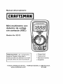
1
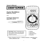
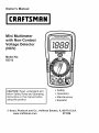
Owner's Manual
Mini Multimeter
with Non-Contact
Voltage
(NCV)
Detector
Model No.
82312
CAUTION: Read, understand and
follow Safety Rules and Operating
Instructions in this manual before
• Safety
using this product.
• EspafioI
O Sears, Roebuck and Co., Hoffman
www.craftsman.com
• Operation
• Maintenance
Estates,
IL 60179 U.S.A.
071006
IP'._:| II :[o] |o[o]
_ I / :1_ i I_
Warranty ............................................................................................
Safety Instructions ............................................................................
Safety Symbols .................................................................................
Controls And Jacks ...........................................................................
Symbols ............................................................................................
Specifications ....................................................................................
Battery Installation ..........................................................................
Operating Instructions ....................................................................
Non-Contact AC Voltage Detector .............................................
AC Voltage Measurements .........................................................
DC Voltage Measurements .........................................................
Battery Voltage Test ...................................................................
AC / DC Current Measurements .................................................
Resistance Measurements .........................................................
Continuity Check .........................................................................
Diode Test ...................................................................................
Maintenance ...................................................................................
3
4
5
6
7
8
11
12
13
14
15
16
17
18
19
20
21
Low Battery Indication ....................................................................
Battery Replacement ......................................................................
Replacing The Fuses ......................................................................
Troubleshooting ..............................................................................
Service And Parts ...........................................................................
21
22
22
24
24
D]_ I=li'd =!':1t,I =1II I IlVlVl:l t,]tJ':l _i I_
ONE YEAR FULL WARRANTY ON CRAFTSMAN MULTIMETER
If this CRAFTSMAN Multimeter fails to give complete satisfaction within
one year from the date of purchase, RETURN IT TO THE NEAREST
SEARS STORE OR OTHER CRAFTSMAN OUTLET IN THE UNITED
STATES, and Sears wiii replace it, free of charge.
This warranty gives you specific legal rights, and you may also have
other rights which vary from state to state.
Sears, Roebuck and Co., Dept. 817WA, Hoffman Estates, IL 60179
For Customer Assistance
Call 9am - 5pm (ET)
Monday through Friday 1-888-326-1006
WARNING:
USE EXTREME
CAUTION
IN THE
USE
OF THIS
DEVICE.
Improper
use of this device can result in injury or
death, Follow all safeguards
suggested
in this manual
in addition
to the normal safety precautions
used in working
with electrical
circuits, DO NOT service this device if you are not qualified
to do
so,
This meter has been designed for safe use, but must be
operated with caution. The rules listed below must be carefully
followed for safe operation.
NEVERapplyvoltage or current to the meterthat exceedsthe specified
maximum:
Input Protection
Function
Limits
Maximum Input
V DC or V AC
600V AC and DC
mA AC/DC
200mA DC/AC
AAC/DC
10A DC/AC (for 30 seconds max.
every 15 minutes)
Resistance,
Continuity
Diode Test,
250V DC/AC
2.
USEEXTREMECAUTIONwhenworking with high voltages.
3.
DONOT measurevoltageif the voltageon the "COM" inputjack exceeds
600V aboveearth ground.
NEVERconnectthe meterleads acrossa voltagesource while thefunction
switch is inthe current, resistance,or diode mode. Doingso can damage
the meter.
4.
5.
6.
7.
8.
ALWAYS dischargefilter capacitors inpower suppliesanddisconnectthe
powerwhen makingresistanceor diode tests.
ALWAYS turn off power and disconnecttest leadsbeforeopeningthe
covers to replacethe fuse or battery.
NEVERoperatethe meter unlessthe back cover and the batteryandfuse
covers are in place andfastenedsecurely.
If the equipmentis used in a mannernot specifiedby the manufacturer,the
protectionprovidedby the equipmentmay be impaired.
+.*I_1:11
Ik'dl,.'b'd
_v+
I:[o] I!_
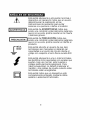
This symbol adjacent to another symbol,
terminal or operating device indicates that the
operator must refer to an explanation in the
Operating Instructions to avoid personal injury
or damage to the meter.
L WARNING
]
This WARNING symbol indicates a potentially
hazardous situation, which if not avoided,
could result in death or serious injury.
CAUTION symbol indicates a potentially
! cAOT'°N
I This
hazardous situation, which if not avoided, may
result damage to the product.
r
600V
MAX
This symbol advises the user that the
terminal(s) so marked must not be connected
to a circuit point at which the voltage with
respect to earth ground exceeds 600V.
This symbol adjacent to one or more terminals
identifies them as being associated with
ranges that may, in normal use, be subjected
to particularly hazardous voltages. For
maximum safety, the meter and its test leads
should not be handled when these terminals
are energized.
This symbol indicates that a device is
protected throughout by double insulation or
reinforced insulation.
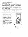
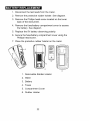
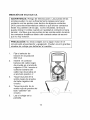
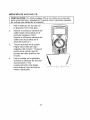
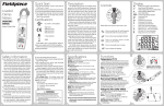
_o] _i / _To]iF.']r_*l_Ie]PF_*To_
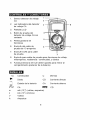
[(_
1. AC Voltage Detector Sensor
1
2.
AC Voltage Detector
indicator light
z
3.
LCD display
4.
Non-contact AC Voltage
Detector test button
5,
Rotary function dial
6.
10 ampere test lead jack
7.
COM test lead jack
8.
Test lead jack for voltage,
milliamp,
resistance/contin uity, and
diode functions
Protective rubber holster
3
4
7
(must be removed to access the rear battery compartment)
[(,.-._"d
_vj
I-[e] _-.]
.)))
Continuity
Diode
Battery status
AC
mmm
DC
m
milli
k
kilo
V
Volts
A
Amps
Ohms
£-)
AC
DC
(10 -3)
(10
3)
(volts, amps)
(ohms)
Alternating current
Direct current
_'.,1_[l! IiI [___1t [.] __
Function
Range
Noncontact AC
100 to Resolution & accuracy do not apply since
600V
the meter does not display the voltage in
this mode. The lamp at the top of the
meter's display flashes when voltage is
sensed and an audible warning will sound.
Voltage
detector
Resolution
Accuracy
DC Voltage
200mV
0.1 mV
_+(0.5% reading + 2 digits)
(V DC)
2000m
V
lmV
20V
0.01V
200V
0.1V
600V
1V
_+(1.5% reading + 2 digits)
AC Voltage
(VAC)
50/60Hz
200V
0.1V
_+(1.5% reading + 3 digits)
600V
1V
_+(2.0% reading + 4 digits
DC Current
200mA
0.1mA
_+(1.5% reading + 2 digits)
_+(1.0% reading + 2 digits)
(A DC)
10A
0.01A
_+(2.5% reading + 5 digits)
ACCurrent
200mA
0.1mA
_+(1.8% reading + 5 digits)
(AAC)
50/60Hz
10A
0.01A
Resistance
200£-2
0.1£-2
_+(3.0% reading + 7 digits)
_+(1.2% reading + 4 digits)
2000£-2 1£-2
20k£-2
0.01k£-2
_+(1.2% reading + 2 digits)
200k£-2 0.1k£-2
2000k£-2 1k£-2
Notes:
Accuracy
specifications
consist
oftwoelements:
• (%reading)
- Thisistheaccuracy
ofthemeasurement
circuit.
• (+digits)
- Thisistheaccuracy
oftheanalog
todigital
converter.
Accuracy
isstated
at65°F
to83°F
(18°C
to28°C)
andlessthan
75%RH.
Diode
Test
Bias voltage: 2.3VDC
Continuity
Check
Audible signal will sound if the
resistance is less than 100£-._
Input Impedance
AC Bandwidth
10MC2(VDC & VAC)
50 ! 60Hz
Display
2000 count (0 to 1999) LCD
Overrange
indication
Polarity
"1
" is displayed
Automatic (no indication for
positive); Minus (-) sign for negative
Measurement
Rate
2 r_times per second, nominal
Low Battery Indication
"LI " is displayed if battery voltage
drops below operating voltage
Battery
Fuses
One (1) 9V battery
mA range; 200mA/250V fast blow
A range; 10A/250V fast blow,
ceramic
Operating
Storage
Temperature
Temperature
Operating
Storage
Humidity
Humidity
Operating
Altitude
32°F to 122°F (0°C to 50°C)
-4°F to 140°F (-20°C to 60°C)
Max 70% up to 87°F (31°C)
decreasing linearly to 50% at 122°F
(50°C)
< 80% RH
7000 ft. (2000 meters) maximum.
Weight
Size
9.17 oz (260g) includes holster
Approvals
CE, UL
5.8" x 2.9" x 1.6" (147 x 76 x 42mm)
includes holster
Safety
ULLISTED
PER IEC1010 OVERVOLTAGE
Thismeter
isintended
forindoor
use
andprotected,
against
theusers,
by
doubleinsulation
perEN61010-1
andIEC61010-1
2ndEdition
(2001)
toCATII 1O00V
& CATIII600V;
Pollution
Degree
2.Themeter
also
meets
UL61010-1,
Second
Edition
(2004),
CAN/CSA
C22.2
No.610101,Second
Edition
(2004),
andUL
61010B-2-031,
First
Edition
(2003)
TheULmarkdoes
notindicate
that
thisproduct
hasbeenevaluated
for
theaccuracy
ofitsreadings.
INSTALLATION
CATEGORY
OVERVOL TAGE CATEGORY I
Equipment of OVERVOLTAGE
CATEGORY I is equipment for
connection to circuits in which measures are taken to limit the
transient overvoltages
to an appropriate
low level. Note Examples include protected electronic circuits.
OVERVOL TAGE CATEGORY II
Equipment
of OVERVOLTAGE
CATEGORY
II is energyconsuming equipment to be supplied from the fixed installation.
Note - Examples include household, office, and laboratory
appliances.
OVERVOL TAGE CATEGORY III
Equipment of OVERVOLTAGE
CATEGORY III is equipment in
fixed installations.
Note - Examples include switches in the fixed installation and
some equipment for industrial use with permanent connection to
the fixed installation.
OVERVOL TAGE CATEGORY
IV
Equipment of OVERVOLTAGE CATEGORY IV is for use at the
origin of the installation.
Note - Examples include electricity meters and primary overcurrent protection equipment
10
I from
WARNING:
an)/source
To avoid
of voltage
electricbefore
shock,removing
disconnect
the batter)/cover.
the test leads
1.
2.
3.
4.
I
Disconnect the test leads from the meter.
Remove the rear battery cover by removing the two screws
using a Phillips head screwdriver.
Insert the battery into battery clips, observing the correct
polarity.
Put the battery cover back in place and secure with the two
screws.
WARNING:
To avoid
shock,
not operate
the meter
until
the battery
cover electric
is in place
and do
fastened
securely.
NOTE: If your meter does not work properly, check the fuses and
batteries to make sure that they are still good and that they
are properly inserted.
11
]|
I
DC, are very dangerous and should be measured with great
I and
WARNING:
Risk
ofelectrocution.
High-voltage
circuits,
both
AC I
care.
NOTE: On some low AC and DC voltage ranges, with the test
leads not connected to a device, the display may show a
random, changing reading. This is normal and is caused by
the high-input sensitivity. The reading will stabilize and give
a proper measurement when connected to a circuit.
12
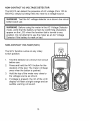
NON-CONTACT
ACVOLTAGE
DETECTOR
TheEX310
candetect
thepresence
ofACvoltage
(from100to
600VAC)
simply
bybeing
heldverynear
toavoltage
source.
WARNING:
TesttheACvoltage
detector
onaknown
livecircuit
before
each
use.
WARNING:
Before
using
themeter
intheACVoltage
Detector
mode,
verify
thatthebattery
isfreshbyconfirming
characters
appear
ontheLCD
when
thefunction
dialisturned
toany
position.
Donotattempt
tousethemeter
asanACVoltage
Detector
ifthebattery
isweak
orbad.
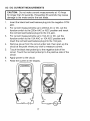
NON-CONTACT
VOLTAGE
(NCV)
TheNCV
function
works
onanyrotary
switch
position.
1. Test
thedetector
onaknown
livecircuit
before
use.
2. Press
andholdtheNCV
button
forthe
duration
ofthetest.Themeter
willbeep
once
when
thebutton
ispushed.
3. Hold
thetopofthemeter
veryclose
to
thevoltage
source
asshown.
4. Ifvoltage
ispresent,
therimoftheLCD
display
willflash
abright
orange
andan
audible
warning will sound.
13
@
AC VOLTAGE
MEASUREMENTS
WARNING: Risk of Electrocution. The probe tips may not be
long enough to contact the live parts inside some 240V outlets
for appliances because the contacts are recessed deep in the
outlets. As a result, the reading may show 0 volts when the
outlet actually has voltage on it. Make sure the probe tips are
touching the metal contacts inside the outlet before assuming
that no voltage is present.
CAUTION:
Do not measure AC voltages if a motor on the
circuit is being switched ON or OFF. Large voltage surges may
occur that can damage the meter.
1.
2.
Set the function switch to
the 600 VAC position.
Insert the black test lead
banana plug into the
negative COM jack. Insert
red test lead banana plug
into the positive V jack.
3.
Touch the black test probe
tip to the neutral side of the
circuit.
4.
Touch the red test probe tip
to the "hot" side of circuit.
5.
Read the voltage in the
display.
14
DC VOLTAGE
MEASUREMENTS
is being switched ON or OFF. Large voltage surges may occur
CAUTION:
Do not measure DC voltages if a motor on the circuit
that can damage the meter.
1.
2.
Set the function switch to the
highest VDC position.
Insert the black test lead
banana plug into the negative
COM jack.
Insert the red test lead
banana plug into the positive
V jack.
3.
Touch the black test probe tip
to the negative side of the
circuit. Touch the red test
probe tip to the positive side
of the circuit.
4.
Read the voltage in the
display. Move the function
switch to successively lower
VDC positions to obtain a
÷
higher resolution reading.
"_
15
I' I' _0
BATTERY VOLTAGE
TEST
CAUTION:
Do not measure batteries while they are installed
in the devices they are powering. The batteries must be
removed from installations before tests can be made.
1.
Set the function switch to the
1.5V or 9V BAT switch position.
Use the 1.5V position for 'AAA',
'AA', 'C', 'D', and other 1.5V
batteries. Use the 9V position
for square 9V transistor
batteries.
2.
Insert the black test lead
banana plug into the negative
COM jack.
Insert the red test lead banana
plug into the positive V jack.
3.
Touch the black test probe tip
to the negative side of the
battery. Touch the red test
probe tip to the positive side of
the battery.
4.
Read the voltage in the display.
16
AC / DC CURRENT
MEASUREMENTS
CAUTION:
Do not make current measurements at 10 Amps
for longer than 30 seconds. Exceeding 30 seconds may cause
damage to the meter and/or the test leads.
1.
Insert the black test lead banana plug into the negative COM
jack.
2.
For current measurements up to 200mA AC or DC, set the
function switch to the 200m AAC or ADC position and insert
the red test lead banana plug into the mA jack.
3.
For current measurements up to 10A AC or DC, set the
function switch to the 10A AAC or 10A ADC position and
insert the red test lead banana plug into the 10A jack.
4.
Remove power from the circuit under test, then open up the
circuit at the point where you wish to measure current.
5.
Touch the black test probe tip to the negative side of the
circuit. Touch the red test probe tip to the positive side of the
circuit.
6.
Apply power to the circuit.
7.
Read the current in the display.
17
I
I
RESISTANCE
MEASUREMENTS
WARNING: To avoid electric shock, disconnect power to the
unit under test and discharge all capacitors before taking any
resistance measurements.
Set the function switch to
the highest _2 position.
2.
3.
Insert the black test lead
banana plug into the
negative COM jack.
Insert the red test lead
banana plug into the
positive £-2jack.
4.
5.
Touch the test probe tips
across the circuit or part
under test. It is best to
disconnect one side of the
part under test so the rest
of the circuit will not
interfere with the resistance
reading.
Read the resistance in the
display. Move the function
switch to successively
lower £-2positions to obtain a higher resolution reading.
18
CONTINUITY
WARNING:
on circuits
1.
2.
3.
CHECK
To have
avoid aelectric
that
voltage shock,
potential,never
measure
continuity
Set the function switch
to the -I_ -)))position.
Insert the black lead
banana plug into the
negative COM jack.
Insert the red test lead
banana plug into the
positive £--)jack.
4.
5.
Touch the test probe
tips to the circuit or
wire you wish to check.
If the resistance is less
than approximately
100£-.),the audible
signal will sound. If the
circuit is open, the
display will indicate
"1
+
\./
19
DIODE
TEST
1. Setthefunction
switch
tothe-I)l--)_
position.
2. Insert
theblack
testlead
banana
plugintothenegative
COM
jackandtheredtest
leadbanana
plugintothe
positive
-IN-jack.
3. Touch
thetestprobes
tothe
diode
under
test.
4. Agood
diode
will indicate
approx. 700 ohms for the
forward test and "1
"for the
reverse test.
5.
A shorted diode will indicate
the same value of resistance
in both the reverse and
forward test directions. An
+
open diode will indicate "1
in both test directions.
20
from any source of voltage before removing the back cover or
J WARNING: To avoid electric shock, disconnect the test leads
the battery or fuse covers.
I
until the battery and fuse covers are in place and fastened
ARNING: To avoid electric shock, do not operate your meter
securely.
This MultiMeter is designed to provide years of dependable
if the following care instructions are performed:
1.
2.
3.
4.
5.
6.
service,
KEEP THE METER DRY. If it gets wet, wipe it off.
USE AND STORE THE METER IN NORMAL
TEMPERATURES.
Temperature extremes can shorten
the life of the electronic parts and distort or melt plastic
parts.
HANDLE THE METER GENTLY AND CAREFULLY.
Dropping it can damage the electronic parts or the case.
KEEP THE METER CLEAN, Wipe the case occasionally
with a damp cloth. DO NOT use chemicals, cleaning
solvents, or detergents.
USE ONLY FRESH BATTERIES OF THE
RECOMMENDED SIZE AND TYPE. Remove old or
weak batteries so they do not leak and damage the unit.
IF THE METER IS TO BE STORED FOR A LONG
PERIOD OF TIME, the battery should be removed to
prevent damage to the unit.
I[olvlVll
:yzlu
innl=1r,b"dlI#Im][o,7zlu
nl[o],'
I
any source of voltage before removing the battery cover. Do not
ARNING: To avoid electric shock, disconnect the test leads from
operate meter unless the battery is in place.
LOW BATTERY INDICATION
The _ icon will appear in the lower left-hand corner of the
display when the battery voltage becomes low. Replace the
batteries when this appears.
21
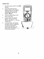
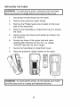
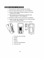
I
',_-'_n
n/d_I;_i'il;__I".,]
if_,_ _I_v_
I_I_i
1. Disconnect the test leads from the meter.
2. Remove the protective rubber holster. See diagram.
3. Remove the Phillips head screw located on the lower
back of the instrument.
4. Remove the fuse/battery compartment
the battery. See diagram.
cover to access
5. Replace the 9V battery observing polarity.
6. Secure the fuse/battery
Phillips head screw.
compartment
cover using the
7. Place the protective rubber holster on the meter.
4
6
1. Removable Rubber Holster
2. Meter
3. Battery
4.
Fuses
5. Compartment
Cover
6. Rubber Holster
22
REPLACING THE FUSES
I from
WARNING:
To avoid
electricbefore
shock,removing
disconnect
the test
leads
any source
of voltage
the fuse
cover.
1.
Disconnect the test leads from the meter.
2.
Remove the protective rubber holster.
3.
Remove the Phillips head screw located on the lower
back of the instrument.
4.
Remove the fuse/battery
the fuses.
5.
Gently remove the fuse(s) and install new fuse(s) into
the holder(s).
6.
Always use fuses of the proper size and value
(200mA/250V fast blow for the mA / #A ranges,
10A/250V fast blow for the A range).
7.
Secure the fuse/battery
8.
Place the protective rubber holster on the meter.
compartment
compartment
II
cover to access
cover.
6
I WARNING:
avoidis electric
do not operate
until the fuseTo
cover
in place shock,
and fastened
securely.your meter
23
I
/ ;(ellJ :] II :[_ -"[ele]l i I_[€
There may be times when your meter does not operate properly.
Here are some common problems that you may have and some
easy solutions to them.
Meter Does Not Operate:
1. Always read all the instructions in this manual before use.
2. Check to be sure the battery is properly installed.
3. Check to be sure the battery is good.
4. If the battery is good and the meter still doesn't operate, check
to be sure that both ends of the fuse are properly installed.
If You Do Not Understand
How the Meter Works:
1. Purchase *'Multitesters and Their Use for Electrical Testing",
(Item No. 82303).
2. Call our Customer Service Line 1-888-326-1006.
_ :1_kvJ[e,]:lr.,1_irail_/'.,I_JII_
Item Number
82374
93894
82312-L
Description
Fuse kit
9V battery
Set of black and red Test Leads
82312-D
82312-C
82312-CS
82394
Replacement battery cover
Front Cover
Rear cover screws
Thermocouple probe
For replacement parts shipped directly to your home
Call 9 am - 5 pm Eastern Time, M - F
1-888-326-1006
24
Manual del propietario
#
Mini multimetro
con
detector de voltaje
sin contacto (VSC)
Modelo No. 82312
PRECAUCION: Lea, comprenda y
siga las Reglas Seguridad e
Instrucciones de operaci6n en este
manual antes de usar el producto.
© Sears, Roebuck and Co.,
www.craftsman.com
•
•
•
•
Seguridad
Operaci6n
Mantenimiento
EspafioI
Hoffman Estates, IL 60179 U.S.A.
071006
Garantia
Instrucciones de Seguridad
Sefiales de Seguridad
Controles y Conectores
Sefiales
Especificaciones
Instalaci6n de la bateria
Instrucciones de operaci6n
Detector de voltaje CA sin contacto
Medici6n de voltaje CA
Medici6n de voltaje CD
Prueba de voltaje de bateria
Medici6n de corriente CA/CD
Medidas de resistencia
Verificaci6n de continuidad
Prueba de diodo
Mantenimiento
Indicaci6n de bateria debil
Reemplazo de la bateria
Reemplazo de los fusibles
Soluci6n de problemas
Servicio y repuestos
Pagina
3
4
5
6
6
7
10
11
11
12
13
14
15
16
17
18
19
19
2O
21
22
22
GARANTiA TOTAL POR UN ANO EN EL MULTiMETRO CRAFTSMAN
Si este multimetro CRAFTSMAN no le satisface totalmente dentro del
primer a_o a partir de la fecha de compra, REGRt_SELO A LA TIENDA
SEARS O DISTRIBUIDOR CRAFTSMAN M,_,S CERCANO EN LOS
ESTADOS UNIDOS, y Sears Io reemplazar& sin cargos.
Esta garantia la otorga derechos legales especificos, ademas de otros
derechos variables entre estados que usted pueda tenet.
Sears, Roebuck and Co., Dept. 817 WA, Hoffman Estates, IL 60179
Para ayuda al cliente Llame entre 9 a,m, y 5 p,m, (Hora del Este)
Lunes a Viernes 1-888-326-1006
ADVERTENCIA:
EXTREME SUS PRECAUCIONES
AL USAR
ESTE DISPOSITIVO. El uso inapropiado de este dispositivo
puede causar lesiones o la muerte. Cumpla todas las
salvaguardas sugeridas en este manual ademas de las
precauciones de seguridad habituales usadas al trabajar con
circuitos electricos. NO de servicio a este dispositivo si usted no
esta calificado para hacerlo.
k
(
ok
m
_. m_,m
Este medidor ha sido dise_ado para uso seguro, sin embargo
debe ser operado con precauci6n. Para operar con seguridad
debera cumplir las reglas enumeradas a continuaci6n.
1.
NUNCAapliqueal medidorvoltaje o corrienteque excedalos limites
m&ximosespecificados:
Limites
de protecci6n
Funci6n
Entrada
de alimentaci6n
m&xima
V CD o V CA
600V CA y CD
mA CA/CD
200mA CD/CA
A CA/CD
10A CA/CD (durante 30 segundos
max. cada 15 minutos)
Resistencia, Prueba de
diodo, Continuidad
250V CD/CA
2.
3.
EXTREMESUS PRECAUCIONESal trabajarcon alta tensi6n.
NO midavoltajessi el voltaje en el enchufede entrada"CON" excede
600Vsobretierrafisica.
4.
NUNCAconectelos cables del medidora unafuente devoltaje cuando el
selectordefunci6n est6 en modode corriente, resistenciao diodo. Hacerlo
puededafiaral medidor.
SIEMPREdescarguelos filtroscapacitoresen las fuentesde tensi6ny
desconectela energiaal realizarpruebas de diodo o de resistencia.
SIEMPREapaguela tensi6ny desconectelos cables de prueba antes de
abrirla tapa para reemplazarlabateria o fusible.
NUNCAopere el medidora menosque la tapa posteriory la tapa de la
bateriay de fusiblesest6n colocadasy aseguradas.
Si el equipo esusado en unamanerano especificadapor el fabricante,la
protecci6nsuministradapor el equipo puedeser afectada.
5.
6.
7.
8.
_ =1_P':_m=B,Im]
l
=1£,_
=[_u];._11
mT:_
m
±
ADVERTENCIA
I
PRECAUCION
F
m
m
m
600V
AX.
Esta seSal adyacente a otra seSal, terminal o
dispositivo en operaci6n indica que el usuario
debera buscar la explicaci6n en las
Instrucciones de operaci6n para evitar
lesiones a su persona o daSos al medidor.
Esta seSal de ADVERTENClA
indica que
J existe una condici6n potencialmente peligrosa,
que si no se evita, podria resultar en la muerte
o lesiones graves.
Esta sepal de PRECAUCION indica que
J existe una condici6n potencialmente peligrosa,
que si no se evita, podria resultar en daSos al
producto.
Esta seSal advierte al usuario de que la(s)
terminal(es) asi marcadas no deberan ser
conectadas a un punto del circuito donde el
voltaje con respecto a tierra fisica exceda 600
V.
Esta seSal adyacente a una o mas terminales
las identifica como asociadas con escalas que
pueden, bajo uso normal, estar sujetas a
voltajes particularmente peligrosos. Para
maxima seguridad, no debera manipular el
medidor y sus cables de prueba cuando estas
terminales esten energizadas.
Esta seSal indica que un dispositivo esta
completamente protegido mediante doble
aislante o aislamiento reforzado.
o[o]_i / _,[o]III:F._]k'|o[o]_I:[_ I[O]_,t:[_
1,
Sensor detector de voltaje
CA
1
2
2.
Luz indicadora del detector
de voltaje CA
3
3.
Pantalla LCD
4.
Bot6n de prueba del
detector de voltaje CA sin
contacto
5,
Perilla giratoria de
funciones
6.
Enchufe del cable de
prueba de 10 amperios
7.
Enchufe COM para cable
de prueba
8.
Enchufe para cable de prueba para funciones de voltaje,
miliamperios, resistencia ! continuidad, y diodos
9.
Funda protectora de hule (debe quitarla para entrar al
compartimiento posterior de la bateria)
7
Continuidad
£._
Ohmios
"_
Diodo
CD
Corriente directa
_]
Estado de la bateria
CA
Corriente alterna
CA
Emm
CD
•)))
m
mili (10 4) (voltios, amperios)
k
kilo (10 s) (ohmios)
V
Voltios
A
Amperios
=[,,,",)
",,,1
=[_]I_1[_I':__][e)_I=[_
Funci6n
Escala
Detector de
100
600V
voltaje CA
sin contacto
Resoluci6n
Voltaje CD
200mV
0.1mY
(V CD)
2000m
V
1mY
20V
0.01V
200V
0.1V
600V
Voltaje CA
(VCA)
50/60Hz
Corriente
CD
±(0.5%lectura
+ 2 digitos)
±(1.0%lectura
+ 2 digitos)
1V
±(1.5%lectura
+ 2 digitos)
200V
0.1V
±(1.5%lectura
+ 3 digitos)
600V
1V
±(2.0%lectura
+ 4 digitos
200mA
0.1mA
±(1.5%lectura
+ 2 digitos)
10A
0.01A
±(2.5%lectura
+ 5 digitos)
200mA
0,1mA
±(1.8%lectura
+ 5 digitos)
10A
0.01A
±(3.0%lectura
+ 7 digitos)
(A CD)
Corriente
CA
(ACA)
50/60Hz
Resistencia
Precisi6n
a ResoluciSn y orecisiSn no son aplicables
ya que el medidor no indica los voltajes en
este modo. La lampara arriba de la
oantalla del medidor destella al detectar
voltaje y sonara una advertencia audible.
200_
0.1_
2000_
1_
20k_
0.01k_
200k_
0.1k_
2000k_
lk_
±(1.2% lectura + 4 digitos)
±(1.2% lectura + 2 digitos)
Notas:
Lasespecificaciones
deprecisiSn
consisten
dedoselementos:
• (%delectura)
-Esta
eslaprecisiSn
delcircuito
demedidas.
•(+digitos)
- PrecisiSn
delconvertidor
analSgico
adigital.
LaprecisiSn
estaespecificada
de18°C
a28°C
(65°F
a83°F)
y
menos
de75%HR.
Prueba
dediodo
Voltaje
depolarizaciSn:
2.3VCD
Verificaci6n
decontinuidad
Seemitira
unaseSal
audible
sila
resistencia
esmenor
a 100£-._
Impedancia
deentrada 10M£2
(VCD
yVCA)
Amplitud
debanda
CA 50/60Hz
Pantalla
LCDde2000
cuentas
(0a 1999)
Indicaci6n
defuera
deescalaindica
"1
Polaridad
Automatica
(sinindicaciSn
para
positivo);
Signo
demenos
(-)para
negativo
Tasa
demedidas
2veces
porsegundo,
nominal
Indicaci6n
debateria
d6bil "LJ"sielvoltaje
delabateria
cae
bajodelvoltaje
deoperaciSn
Bateria
Una
(1)bateria
de9V
Fusibles
Escala
mA;200mA/250V
de
quemado
rapido
Escala
A;10A/250V
dequemado
rapido,
ceramica
Temp.
deoperaci6n
0°Ca50°C
(32°F
a122°F)
Temp.
dealmacenamiento
-20°C
a60°C
(-4°F
a140°F)
Humedad
deoperaci6n 70%
max.
hasta
31°C(87°F)
con
disminuciSn
linear
hasta
50%
a
50°F
(122°F)
Humedad
dealmacenamiento
<80%HR
Altitud
deoperaci6n 2000
metros
(7000ft.)
maximo
Peso
260g
(9.17
oz.)incluye
funda
TamaSo
147X76X42mm
(5.8"
X2.9"X1.6")
incluye
funda
Aprobaci6n
CE, UL
Seguridad
este medidor es para uso en interiores y
protegido, contra usuarios, por doble aislante
conforme a EN61010-1
y IEC61010-1
2°
Edici6n (2001) para CAT II 1000V y CAT III
600V; Grado de contaminaci6n 2. El medidor
ademas cumple con UL 61010-1, Segunda
edici6n (2004), CAN/CSA C22.2 No. 61010-1,
Segunda edici6n (2004), y UL 61010B.-2-031,
Primera edici6n (2003)
La marca UL no indica que este producto ha
sido evaluado en cuanto a la precisi6n de sus
lecturas.
Inscrito en UL
POR CATEGORIAS
IEC
DE SOBREVOLTAJE
DE INSTALAClON
CATEGORiA DE SOBRE VOLTAJE I
Equipo of CATEGORJA DE SOBRE VOLTAJE I es equipo para
conectar a circuitos en los que se hart tornado medidas para
limitar los sobre voltajes transitorios a niveles bajos. Nota - Los
ejemplos incluyen circuitos electricos protegidos.
CATEGORiA DE SOBRE VOLTAJE II
El equipo de CATEGORJA DE SOBRE VOLTAJE II es equipo
que consume energia suministrada desde una instalaci6n fija.
Nota - Los ejemplos incluyen equipos electricos del hogar,
oficina y laboratorio.
CATEGORiA DE SOBRE VOLTAJE III
El equipo de CATEGORJA DE SOBRE VOLTAJE III es el
equipo en instalaciones fijas.
Nota - Los ejemplos incluyen interruptores en instalaciones fijas
y algunos
equipos
de uso industrial
con
conexiones
permanentes a instalaciones fijas.
CATEGORiA DE SOBRE VOLTAJE IV
El equipo de CATEGORiA
DE SOBRE VOLTAJE IV es para
uso en el origen de la instalaci6n.
Nota - Los ejemplos incluyen medidores de electricidad y el
equipo primario de protecci6n de sobre voltaje
I
deprueba
decualquier
fuente
devoltaje
antes
dequitar
I cables
ADVERTENClA:
Para
evitar
choque
electrico,
desconecte
los
la tapa de la bateria.
1.
2.
3.
4.
Desconecte los cables de prueba del medidor.
Quite los dos tomillos de la tapa posterior (B) con un
destomillador Phillips.
Inserte la bateria en el porta bateria, observando la polaridad
correcta.
Coloque la tapa de la bateria en su lugar y asegure con los
dos tomillos.
medidor a menos que la tapa posterior y la tapa de la bateria y
I ADVERTENClA:
Para evitar choque electrico, no opere el
fusibles esten colocadas y aseguradas.
NOTA: Si su medidor no funciona apropiadamente, revise los
fusibles y la bateria para asegurar que estan en buenas
condiciones y que estan correctamente instalados.
10
I
I
_.
i
_
O_.
II
O"
__A
O_.
iesoodee,ect
I
tensidn, tanto de CA g CD, son mug peligrosos
medidos con gran cuidado.
g deberan
ser
NOTA: En algunas escalas bajas de voltaje CA g CD, sin estar
los cables de prueba conectados
a dispositivo alguno, la
pantalla puede mostrar una lectura aleatoria cambiante.
Esto es
normal g es causado por la alta sensibilidad
de la alimentacidn.
La lectura se estabilizara
g data una medida apropiada al estar
conectada
a un circuito.
DETECTOR DE VOLTAJE CA SIN CONTACTO
El EX310 puede detectar voltaje CA (de 100 a 600 VCA;)
simplemente al colocarse en la proximidad de una fuente de
voltaie.
ADVERTENClA: Pruebe el detector de voltaje CA en un circuito
vivo conocido antes de cada uso.
ADVERTENClA:
Antes de usar el medidor en modo detector de I
voltaje CA, verifique la carga de la bateria confirmando que se
I
ven los caracteres en la LCD al girar la perilla a cualquier
|
posiciSn. No intente usar el medidor como detector de voltaje CA_
si la bateria esta debil o mala.
|
VOLTAJE SIN CONTACTO (VSC)
La funciSn VSC trabaja en cualquier posiciSn
del interruptor giratorio.
1. Pruebe el detector de voltaje CA en un
circuito vivo conocido antes de cada uso.
2. Presione y sostenga el bot6n NCV (VSC)
durante la duraciSn de la prueba. El
medidor pitara una vez al presionar el
botSn.
3.
Sostenga la parte superior del medidor
muy cerca de la fuente de voltaje como se
indica.
4.
Si hay voltaje presente, la orilla de la
pantalla LCD brillara naranja intenso y
sonara una advertencia audible.
11
@
@
T
©
©
MEDICION
DE VOLTAJE
CA
ADVERTENCIA: Riesgo de electrocuci6n. Las puntas de las
sondas pueden no ser suficientemente largas para hacer
contacto con las partes vivas dentro de algunos contactos
240V para electrodomesticos debido a que dichos contactos
estan muy adentro de la caja. Como resultado, la lectura
puede indicar 0 voltios cuando en realidad el contacto si tiene
tensi6n. Verifique que las puntas de las sondas estan tocando
los contactos metalicos dentro del contacto antes de asumir
que no hay tensi6n.
PRECAUCION: No mida voltajes CA si algQn motor en el
circuito esta encendiendo y apagando. Pueden ocurrir grandes
oleadas de voltaje que daSarian al medidor.
1.
Fije el selector de
funci6n en la posici6n
600 VCA
2.
Inserte
el conector
banana del cable negro
de prueba en el enchufe
negativo COM. Inserte el
conector banana del
cable rojo de prueba en
el enchufe positivo V.
3.
Toque la punta de la
sonda negra de prueba
del lado negativo del
circuito.
4.
Toque la punta de la
sonda roja de prueba del
lado "caliente" del
circuito.
5.
Lea el voltaje en la
pantalla.
12
MEDICION
DE VOLTAJE
CD
esta encendiendo y apagando. Pueden ocurrir grandes oleadas
PRECAUCION: No mida voltajes CD si un motor en el circuito
de voltaje que daSarian al medidor.
1.
2.
Fije el selector de funci6n en
la posici6n VCD mas alta.
Inserte el conector banana del
cable negro de prueba en el
enchufe negativo COM.
Inserte el conector banana del
cable rojo de prueba en el
enchufe positivo V.
3.
Toque la punta de la sonda
negra de prueba del lado
negativo del circuito. Toque la
punta de la sonda roja de
prueba del lado positivo del
circuito.
4.
Lea el voltaje en la pantalla.
Cambie el selector de funci6n
a posiciones V CD
sucesivamente mas bajas
para obtener una lectura de
mayor resoluci6n.
13
PRUEBA
DE VOLTAJE
PRECAUCION:
DE BATERiA
No medir
baterias
mientras
esten
en los dispositivos
que alimentan,
Debe quitar
su instalaci6n
antes de realizar
las pruebas,
1.
Fije el selector de funci6n en la
posici6n 1.5V o 9V BAT. Use la
posici6n 1.5V para baterias
'AAA', 'AA', 'C', 'D' y otras de
1.5V. Use la posici6n 9V para
baterias cuadradas de 9V para
transistores.
2.
Inserte el conector banana del
cable negro de prueba en el
enchufe negativo COM.
Inserte el conector banana del
cable rojo de prueba en el
enchufe positivo V.
3.
Toque la punta de la sonda
negra de prueba del lado
negativo de la bateria. Toque
la punta de la sonda roja de
prueba del lado positivo de la
bateria.
4.
Lea el voltaje en la pantalla.
14
instaladas
las baterias
de
MEDICION
DE CORRIENTE
CA/CD
durante mas de 30 segundos. Exceder 30 segundos puede
I PRECAUCION:
No tome y/o
medidas
de corriente
sobre 10A
causar dafios al medidor
a los cables
de prueba.
1.
Inserte el conector banana del cable negro de prueba en el
enchufe negativo COM.
2.
Para medidas de corriente hasta 200mA CD o CA, fije el
selector de funci6n en la posici6n 200m ACD o ACA e inserte
el conector banana del cable rojo de prueba en el enchufe
mA.
3.
Para medidas de corriente hasta 10A CA o DC, fije el selector
de funci6n en la posici6n 10A AAC o 10A ADC e inserte el
conector banana del cable rojo de prueba en el enchufe 10A.
Corte la tensi6n del circuito bajo prueba, enseguida abra el
circuito en el punto donde desea medir la corriente.
4.
5.
Toque la punta de la sonda negra de prueba del lado
negativo del circuito. Toque la punta de la sonda roja de
prueba del lado positivo del circuito.
6.
Aplique tensi6n al circuito.
7.
Lea la corriente en la pantalla.
15
I
MEDIDAS DE RESISTENCIA
ADVERTENCIA: Para evitar choque electrico, desconecte la
tensiSn a la unidad bajo prueba y descargue todos los
capacitores antes de tomar cualquier medidas de resistencia.
1.
Fije el selector de funciSn a
la posiciSn £-._mas alta.
2.
Inserte el conector banana
del cable negro de prueba
en el enchufe negativo
COM.
3.
Inserte el conector banana
del cable rojo de prueba en
el enchufe positivo £-._.
4.
Toque las puntas de las
sondas a traves del circuito
o parte bajo prueba. Es
mejor desconectar un lado
de la pieza bajo prueba
para que el resto del
circuito no interfiera con la
lectura de resistencia.
5.
Lea la resistencia en la
,____
pantalla. Cambie el
selector de funci6n a posiciones £-2sucesivamente
para obtener una lectura de mayor resoluci6n.
÷
16
mas bajas
VERIFICACION
DE CONTINUIDAD
ADVERTENClA:
Para evitar choque electrico, nunca mida
continuidad en circuitos que tengan voltaje potencial.
1.
Fije el selector de
funci6n en la
posici6n _-))).
2.
Inserte el conector
banana del cable
3.
4.
5.
negro de prueba en el
enchufe negativo
(COM.
Inserte el conector
banana del cable rojo
de prueba en el
enchufe positivo £-2.
Toque las puntas de
las sondas al circuito o
alambre que desee
probar.
Si la resistencia es
--
menor a
aproximadamente
_-__--------_
_
100£-2,sonara una
seSal audible. Si el circuito esta abierto, la pantalla indicara
"1
".
17
+
_.
PRUEBA
DE DIODO
1.
2.
Fije el selector de funci6n en
la posici6n -IN-))).
Inserte el conector banana del
cable negro de prueba en el
enchufe negativo COM y el
conector banana del cable
rojo de prueba en el enchufe
positivo -IN.
3.
4.
Toque las puntas de las
sondas al diodo bajo prueba.
Un diodo bueno indicara
aproximadamente 700 ohmios
para la prueba hacia adelante
y "1i"
para la prueba en
reversa.
5.
Un diodo en corto indicara el
mismo valor de resistencia en
--
ambas direcciones de prueba.
Un diodo abierto indicara
"1
" en ambas direcciones de prueba.
18
+
©
,v_
!'__1
_IIII_1_II_V_l
I_1_IIl[O
cables de prueba de cualquier fuente de voltaje antes de quitar
I la DVERTENClA:
evitar
desconecte los
tapa posterior oPara
la tapa
de choque
la bateriaelectrico,
o fusibles.
choque
no
opere
medidor a menos que la tapa posterior y la tapa de la bateria y
I ADVERTENCIA: Para evitar
electrico,
el
fusibles esten colocadas y aseguradas.
Este Multimetro esta diseSado para proveer muchos aSos de
servicio confiable, si se Ilevan a cabo las siguientes instrucciones
de cuidado del manual:
1.
2.
3.
4.
5.
6.
k mm
MANTENGA SECO EL MEDIDOR. Si se moja, sequelo.
USE Y ALMACENE EL MEDIDOR BAJO TEMPERATURA
NORMAL. Los extremos de temperatura pueden acortar la
vida de las partes electr6nicas y distorsionar o fundir las
piezas de plastico.
MANIPULE EL MEDIDOR CON SUAVlDAD Y CUIDADO.
Dejarlo caer puede daSar las partes electr6nicas o la caja.
MANTENGA EL MEDIDOR LIMPIO. Ocasionalmente
limpie la caja con un paso hQmedo. NO use quimicos,
solventes para limpieza o detergentes.
USE SOLO BATERIAS NUEVAS DEL TAMANO Y TIPO
RECOMENDADO. Retire las baterias viejas o debiles de
manera que no se derramen y daSen la unidad.
Sl VA A ALMACENAR
EL MEDIDOR DURANTE UN
LARGO PERIODO DE TIEMPO, debera retirar la bateria
para prevenir daSos a la unidad.
mA
Ok
mm
_-_A
_ _A I
-"
I
de cualquier fuente de voltaje antes de quitar la tapa de la bateria. No
I ADVERTENClA: Para evitar choque electrico, desconecte los cables I
ha_a funcionar al medidor si la bateria no est_t en su lunar.
INDICACION DE BATERiA DIeBIL
El icono _ aparecer_l en la esquina inferior izquierda de la
pantalla cuando baje el voltaje de la bateria, Remplace las
baterJas cuando este se presente,
19
1.Desconecte
loscables
deprueba
delmedidor.
2.Quite
lafunda
protectora
dehule.
Veaeldiagrama.
3.Quite
eltornillo
cabeza
Phillips
Iocalizado
enlabase
posterior
delmedidor.
4.Quite
latapadelcompartimiento
debaterias
para
alcanzar
labateria.
Veaeldiagrama.
5.Remplace
labateria
de9Vobservando
lapolaridad.
6.Asegure
latapadelcompartimiento
delabateria/fusible
coneltornillo
cabeza
Phillips.
7.Coloque
lafunda
protectora
dehuleenelmedidor.
5
3
1. Funda de hule removible
2. Medidor
3. Bateria
4. Fusibles
5. Tapa del compartimiento
6. Funda de hule
20
REEMPLAZO
DE LOS FUSIBLES
cables de prueba de cualquier
la tapa de fusibles.
fuente
los cables
de voltaje antes
de prueba
de quitar
1.
Desconecte
2.
Quite la funda
3.
Quite el tornillo cabeza
posterior del medidor.
4.
Quite la tapa del compartimiento
alcanzar los fusibles.
5.
Suavemente quite los fusibles e instale los fusibles
nuevos en el porta fusibles.
6.
Use siempre un fusible de tamaSo y valor apropiado
(200mA/250V de quemado rapido para las escalas
mA/pA, 10A/250V de quemado rapido para la escala A).
7.
Asegure la tapa del compartimiento
8.
coloque la funda protectora de hule en el medidor.
protectora
del medidor.
de hule.
Phillips Iocalizado
__
en la base
de baterias para
de la bateria/fusible.
3
4
6
medidor hasta que la tapa de fusibles este colocada y
I ADVERTENCIA:
Para evitar choque electrico, no opere el
asegurada.
21
I
I
.'-[o]lu[e,][o]_II m]:11:,ir,{o]:] ml:l,v_
r.,_
Habra ocasiones en que su medidor no funcione correctamente.
En seguida encontrara algunos problemas comunes que puede
Ilegar a tener y algunas soluciones faciles.
El medidor no funciona:
1. Siempre lea todas las instrucciones en este manual antes de
usar.
2. Revise que la bateria esta bien instalada.
3. Revise que la bateria tenga buena carga.
4. Si la bateria esta en buen estado y el medidor aun no funciona,
revise el fusible para asegurar que ambos extremos esten bien
insertados.
Si usted no comprende c6mo funciona el medidor:
1. Compre "Multitesters and Their Use for Electrical Testing",
(Articulo No. 82303).
2. Llame a nuestra Linea de Servicio al Cliente 1-888-326-1006.
.1 ::1[kvj [e,][e]b'dl [_1::1".lIJ ::_,11lie}:
Nemero
82374
93894
82378
82312-D
82312-C
82312-CS
82377
de articulo
Descripci6n
Kit del Fusible
Bateria 9Va
Juego de cables de prueba rojo y negro
Tapa de bateria de reemplazo
Tapa del frente
Tornillos tapa posterior
Sensor termopar
Para piezas de reemplazo embarcadas directamente a su hogar
Llame de lunes a viemes de 9 a.m. a 5 p.m. hora del este
1-888-326-1006
22