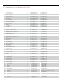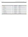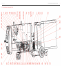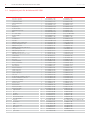
1
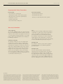
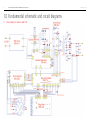
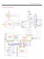
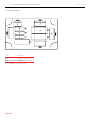
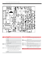
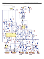
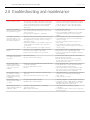
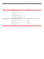
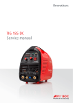
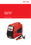
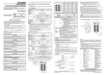
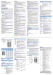
MIG 275R & MIG 350R
Service manual
2
BOC Smoothcut Advance MIG 275R & MIG 350R Service manual
Ver.1 Rev.1 . 0314
Recommended Safety Precautions
Electrical Shock
Avoid electric shock by:
• Never touch ‘live’ electrical parts.
• Wearing dry insulated boots.
• Always repair or replace worn or damaged parts.
• Wearing dry leather gloves.
• Disconnect power source before performing any
maintenance or service.
• Working on a dry insulated floor where possible.
• Earth all work materials.
• Never work in moist or damp areas.
Warranty Information
Terms of Warranty
The Smootharc ADVANCE machine has a limited warranty
that covers manufacturing and material defects only. The
warranty is affected on the day of purchase and does not
cover any freight, packaging and insurance costs. Verbal
promises that do not comply with terms of warranty are
not binding on warrantor.
Limitations on Warranty
The following conditions are not covered under terms
of warranty: loss or damage due to or resulting from
natural wear and tear, non‑compliance with operating
and maintenance instructions, connection to incorrect or
faulty voltage supply (including voltage surges outside
equipment specs), incorrect gas pressure overloading,
transport or storage damage or fire or damage due to
natural causes (e.g. lightning or flood). This warranty
does not cover direct or indirect expenses, loss, damage
of costs including, but not limited to, daily allowances or
accommodation and travelling costs.
NOTE
Under the terms of warranty, welding torches and their
consumables, feed, drive rollers and feeder guide tubes
are not covered. Direct or indirect damage due to a
defective product is not covered under the warranty.
The warranty is void if changes are made to the product
without approval of the manufacturer, or if repairs are
carried out using non-approved spare parts. The warranty
is void if a non-authorised agent carries out repairs.
Warranty Period
The warranty is valid for 3 years from date of purchase
provided the machine is used within the published
specification limits.
Warranty Repairs
Your service provider must be informed within the
warranty period of any warranty defect. The customer
must provide proof of purchase and serial number of
the equipment when making a warranty claim. Warranty
repairs may only be carried out by approved BOC service
providers. Please contact your local BOC Gas & Gear for a
directory of BOC approved service providers in your area.
Important Notice
This document has been prepared by BOC Limited ABN 95 000 029 729 (‘BOC’),
as general information and does not contain and is not to be taken as containing
any specific recommendation. The document has been prepared in good faith
and is professional opinion only. Information in this document has been derived
from third parties, and though BOC believes it to be reliable as at the time of
printing, BOC makes no representation or warranty as to the accuracy, reliability
or completeness of information in this document and does not assume any
responsibility for updating any information or correcting any error or omission
which may become apparent after the document has been issued. Neither BOC
nor any of its agents has independently verified the accuracy of the information
contained in this document. The information in this document is commercial
in confidence and is not to be reproduced. The recipient acknowledges and
agrees that it must make its own independent investigation and should
consider seeking appropriate professional recommendation in reviewing and
evaluating the information. This document does not take into account the
particular circumstances of the recipient and the recipient should not rely on
this document in making any decisions, including but not limited to business,
safety or other operations decisions. Except insofar as liability under any statute
cannot be excluded, BOC and its affiliates, directors, employees, contractors
and consultants do not accept any liability (whether arising in contract, tort or
otherwise) for any error or omission in this document or for any resulting loss
or damage (whether direct, indirect, consequential or otherwise) suffered by
the recipient of this document or any other person relying on the information
contained herein. The recipient agrees that it shall not seek to sue or hold BOC
or their respective agents liable in any such respect for the provision of this
document or any other information.
Ver.1 Rev.1 . 0314
3
BOC Smoothcut Advance MIG 275R & MIG 350R Service manual
Contents.
1.0Fundamental schematic and circuit diagrams
4
1.1 1.2
1.3
4
5
6
Wiring diagram for Advance MIG 275R
Wiring diagram for Advance MIG 350R
Advance MIG 275R/350R boards 2.0Troubleshooting and maintenance
14
3.0
16
Exploded view and component parts list 3.1 Exploded view of Advance MIG 275R
3.2
Component parts list for Advance MIG 275R
3.3Exploded view of Advance MIG 350R
3.4
Component parts list for Advance MIG 350R
16
17
19
20
4
BOC Smoothcut Advance MIG 275R & MIG 350R Service manual
1.0Fundamental schematic and circuit diagrams
1.1 Wiring diagram for Advance MIG 275R
Ver.1 Rev.1 . 0314
Ver.1 Rev.1 . 0314
1.2 Wiring diagram for Advance MIG 350R
BOC Smoothcut Advance MIG 275R & MIG 350R Service manual
5
6
BOC Smoothcut Advance MIG 275R & MIG 350R Service manual
1.3 Advance MIG 275R & MIG 350R boards
1.3.1 Control panel schematic
Ser. No.
Pin
Description
J3
1
2
3
15V
GND
voltmeter
4
5
6
7
8
1
2
3
Ampere meter
GND
Arc characteristic
GND
Volt Set signal
GND
Set wire feed speed
Once pin 4 is at high potential, fast wire speed;
once at low potential, low wire speed
12V
Once pin 5 is at high potential check gas;
once at low potential, do not check gas
12V
NC
NC
Once pin 2 is at high potential, 2T; once at low
potential, 4T
12V
J2
4
5
6
7
8
9
10
Ver.1 Rev.1 . 0314
Ver.1 Rev.1 . 0314
BOC Smoothcut Advance MIG 275R & MIG 350R Service manual
1.3.2 Bottom board schematic
Ser. No. Pin
Description
CON3
CON4
CON6
AC240V
AC240V connect solenoid valve
GND
24V
GND
+DC340V
Solenoid valve relay if the solenoid valve is not pulling in: if 24V relay pulls in solenoid valve
damaged; if 24V relay does not pull in Q1 Z24 circuit damage check it.
Slow starting relay
Field-discharge resistance: if startup frequency is high, field-discharge resistance will break
off cool down for a while and re-start.
CON7
K1
K2
RX1
1
3
1
2
1.3.3 Bottom board circuit diagram
7
8
BOC Smoothcut Advance MIG 275R & MIG 350R Service manual
1.3.4 Fan board schematic
Ser. No.
Description
CON1
CON2
Fan, C5 fan startup capacitor
AC220V input
Notice: :MIG350R has common principle
Caption needed
Ver.1 Rev.1 . 0314
Ver.1 Rev.1 . 0314
9
BOC Smoothcut Advance MIG 275R & MIG 350R Service manual
10
1.3.5 Control board schematic
Ser. No.
Pin
CON1
CON2
CON3
CON4
1
2
1
2
3
4
1
2
CON5
CON6
CON7
CON8
1
2
3
4
1
2
3
Description
DC auxiliary current,MIG275R DC auxiliary current
is 310V,while MIG350R is 540V,if the above DC
auxiliary current needs to be repaired,particular
attention must be paid to the positive and
negative pole
24V
GND
5V
Arc characteristic signal
GND
NC
Current detection signal, if pin 1 is at low potential,
no output current; if high potential, no output
GND
Mutual inductor, current sampled signal
5V
Volt Set signal
Lowest Volt Set signal
GND
CON7 pin 2 voltmeter sampled signal
5V
Ampere sampled signal
GND
Ser. No.
CON9
CON10
CON11
CON12
CON13
CON14
CON15
Pin
1
2
3
4
1
2
3
4
1
2
1
2
3
4
5
6
7
Description
Current feedback signal
GND
Voltage feedback signal
24V
Guard lamp
24V
Power light (NC)
15V
GND
Current detection signal
Drive signal
GND
24V
24V
GND
GND
GND (pin 5 and pin 6 short circuit)
24V seal signal
NC
10
BOC Smoothcut Advance MIG 275R & MIG 350R Service manual
1.3.6 Control board circuit diagram
Ver.1 Rev.1 . 0314
Ver.1 Rev.1 . 0314
BOC Smoothcut Advance MIG 275R & MIG 350R Service manual
1.3.7 Control module schematic
Ser. No.
Description
1
2
3
4
5
6
7
GND
GND
Seal signal pin. Seals if low potential, lower 3525 pin 8.
GND
NC
15V
Overheating protection signal: if low potential, overheating protection
is activated.
NC
Over current protection: Pin 9 is a mutual inductor current sampled signal. If
the potential is higher than the set value, it will close
GND
24V
Set signal
GND
Drive signal
15V
Drive signal
24V
Drive signal
NC
Drive signal
NC
GND
8
9
10
11
12
13
14
15
16
17
18
19
20
21
22
11
12
BOC Smoothcut Advance MIG 275R & MIG 350R Service manual
Ver.1 Rev.1 . 0314
1.3.8 Wire feed board schematic
Ser. No.
Pin
Description
CON1
1
2
3
4
5
6
7
GND
24V
24V
GND
GND
GND (pin 5 and pin 6 short circuit)
24V seal signal
Wire feeder
NC
12V
Check gas. If pin 3 potential is higher, Q6 break
over, solenoid valve pull in, gas feeds.
Current detection signal. If output end current
exists, feeds wire in normally, if no load, no current,
pin 1 has low potential, TL494 pin 2 potential will
be lowered, wire feed speed becomes slow.
GND
NC
CON2
CON3
CON4
1
2
3
1
2
3
Ser. No.
CON5
CON6
CON7
CON8
CON9
CON10
CON11
Pin
1
3
2
1
2
1
Description
If solenoid valve, gas-check and hand switch is
on, solenoid valve should pull in thus allowing gas
feed.
Fan switch signal
12V
2T/4T. If pin 3 potential is high 2T, If low potential,
4T.
NC (wire diameter option))
Wire feed speed set signal, other pins NC
12V
If pin 2 is at high potential, Q8 breaks over, closes,
stable volt D20 reverse break down. TL494 pin 2
high potential, wire feed speed is at maximum
24V.
Ver.1 Rev.1 . 0314
1.3.9 Wire feed board circuit diagram
BOC Smoothcut Advance MIG 275R & MIG 350R Service manual
13
14
BOC Smoothcut Advance MIG 275R & MIG 350R Service manual
Ver.1 Rev.1 . 0314
2.0Troubleshooting and maintenance
Problem
Possible Reasons
1Switch on and no response
1The external power supply is abnormal, power wires may
not be properly connected; (Test point 1, test the input
voltage on the EMC board and power board input pin)
2Rectifier silicon bridge damage causes the input to
short circuit.
2Switch on,fan is working,
1 Torch switch is damaged or the control wire is loose
turn on the switch of welding 2Poor contact of the torch and the power source or wire
torch, but still no response
feeder connections
3 The auxiliary power supply has a circuit failure
3Power light is on, the fan
stops after a while, or once
the torch switch is pressed,
the machine shuts down
4Start up and the air switch
breaks
1Bottom board PZ-60-A degaussing resistance damage, the
main relay K2, 7D361 pressure-sensitive resistor damage
2The supply voltage is too high, causing over-voltage
protection to activate
3Continuously switching on and off within a short period
of time resulting in the startup resistor overheating.
Can’t start up.
4The control board auxiliary power supply is damaged
1Power wire or power supply bottom board short circuit.
2Over-voltage causes damage to the varistor.
3Damage to the silicon bridge causes short circuit
5Start up, no gas feed or valve
not working, other functions
are normal
1Gas circuit is blocked.
2The valve control circuit is damaged
6Press the torch switch,
gas flows, but no voltage
indication in the panel (no
load), wire feeder is not
working
1Measure the control panel PK01-077-A whether the drive
is 24V with a multimeter;
2Seal wave, without drive waveform
3No wave
7Press the torch switch,
gas out, there is a voltage
indication in the panel (no
load) but the wire feeder is
not working
8Press the torch switch,
abnormal indication light on,
no output
1Wire feed board wire feed MOSFET and control circuit
damaged
2Wire feeder control wire③④ broken or poor contact
9Abnormally high welding
current or abnormal indicator
light while welding
1The 2nd rectifier module is damaged
2The IGBT or drive circuit is damaged
1Machine is overheating and causes overheating
protection to activate
2IGBT absorption board failure
Solution
1Check and confirm whether the input voltage into the
machine, no over-voltage or under-voltage condition,
make sure the power cord is connected correctly.
2Test the performance of the rectifier silicon bridge
1 Check the torch control wire
2 Reconnect the wire feeder
3Detect if it’s 24V with a multimeter, if not, check the
control board auxiliary power for any component
damage
1Check and replace the components or bottom board
2Check whether the voltage exceeds AC 380V or grid
voltage is too high
3Stop for a few minutes, allow the resistor to cool
before restart.
4Check whether the auxiliary power part MOSFET,
IC3843, resistors and other components are damaged
and if so, replace.
1Replace the power wire or repair bottom board.
2Replace the varistor, re-adjust the input voltage.
3Check for a short circuit with a multimeter and replace
the silicon bridge
1PZ-60-A relay K1 pulls in, replace the solenoid valve
2Inspect and replace if needed
3If PZ-60-A has 24V, and the relay does not pull in,
then check the valve control circuit components, i.e.
MOSFET, Z24 and wire circuit
1If not 24V, then the R70 (1 ohm) resistor is damaged
2Check whether there is a drive waveform from the
3525 chip, check the circuit in this area;
3Wire feed board PHB-93 control circuit: Check CON1
pin 7. Check seal-wave control signal. If pin 7 high,
transistor Q5 damaged and needs replacing
1Check whether there is a cold joint in wire feed board
PHB-93 Q1;②check TL494 pin 4 potential; If high,
replace TL494
2Check and replace in needed
1Check the performance of rectifier module and replace
2Check the performance of IGBT module or LED light in
the IGBT board, resistors, tantalum capacitors, single
tube IGBT and the diode. Replace board
1Check whether the fan is damage and causes
overheating
2Check IGBT absorption cement resistors, and capacitors.
If damaged, replace.
Ver.1 Rev.1 . 0314
BOC Smoothcut Advance MIG 275R & MIG 350R Service manual
Problem
Possible Reasons
Solution
10Porosity in the weld
1Solenoid valve does not respond:
a Solenoid valve coil broken;
b Solenoid valve cable broken;
c Solenoid voltage control circuit damaged;
2Lack of shielding gas:
a The gas flow rate is too low
b The solenoid valve is blocked
c Check the connection between the cylinder and torch,
also check the inside of the gas tube
dIf using CO2, the regulator heater power supply may not
have been turned on or is not being used.
1 Output controlling voltage is not stable
2 Voltage and current are not adjusted in right position
3 The potentiometer has been damaged
4The unstable current is caused by using incorrect size
contact tip
5 Wire-feeder has been damaged or wire feed rolls are worn
6 Wire-feeder guide tube is aged
7 The torch has been damaged or is worn
8 Wire stick-out is too long
1 Check and replace if needed
2 Adjust or replace
11Welding current unstable
and large spatter
1 Adjust suitable voltage with current.
2 Adjust again
3Replace
4Replace
5Replace
6Replace
7Replace
8 Shorten stick out
15
16
BOC Smoothcut Advance MIG 275R & MIG 350R Service manual
3.0 Exploded view and component parts list
3.1 Exploded view of Advance MIG 275R
Ver.1 Rev.1 . 0314
17
BOC Smoothcut Advance MIG 275R & MIG 350R Service manual
Ver.1 Rev.1 . 0314
3.2 Component parts list for Advance MIG 275R
Item
Description
1
2
3
4
5
6
7
8
9
10
11
12
13
14
15
16
17
18
19
20
21
22
23
24
25
26
27
28
29
30
31
32
33
34
35
36
37
38
39
40
41
42
43
44
45
46
47
48
49
50
51
52
53
54
55
Polyester capacitor
Polyester capacitor
Toroidal transformer
Current transformer
Reactor
Magnet ring
Rectifier module
3P rectifier bridge
LED luminous (yellow)
Thermo switch
Diffuser
Circuit breaker
Fuse tube
MIG 275R control output panel
BOC host front plastic cover
MIG 275R rear panel
MIG 200C/275C/275R/350R chassis
BOC cylinder tray
MIG 275R right side cover
MIG 200C left side cover
MIG 275R left top side active cover
Central board
Partition board
Rear axle
Bottom insulation
Control insulation
Wire feed insulation
3P insulation
EMC insulation
Thermal buffer aluminum
Radiator insulation
Cylinder top plate
Cylinder left plate
Cylinder right plate
Fan cover
Spring
Front roll mounting
Supporting frame
Radiator stand
Capacitor stand
Radiator board
Radiator/heatsink
Radiator/heatsink
Circlip for Shaft
Fan
Fan guard
Wheel rear
Universal wheel front
Self-locking buckle
Push lock
Protection box
Handle
–
Handle screw cover
Wheel cover
Qty
1
2
1
1
1
4
2
1
1
1
1
1
1
1
1
1
1
1
1
1
1
1
1
2
1
1
1
1
1
2
2
1
1
1
2
2
1
1
4
2
1
1
1
2
1
1
2
2
1
2
1
1
–
2
2
Material Part No.
BOC Part No.
R-02-010403-02-00
R-02-010403-04-00
R-03-010303-23-01
R-03-010400-05-00
R-03-020200-27-01
R-03-030200-04-00
R-04-010300-26-00
R-04-010403-02-00
R-04-010700-17-01
R-06-030000-03-01
R-06-060000-10-00
R-07-070003-03-00
N-09-010000-05-00
R-15-019690-01-A0
N-15-900600-01-A0
R-16-037092-01-A2
R-18-171000-01-A1
R-18-205000-01-A0
R-19-067269-03-A1
R-19-068222-01-A1
R-19-069269-03-A0
R-21-049200-01-A1
R-21-051200-01-A0
R-22-043001-01-A0
R-23-010300-56-A0
R-23-010400-12-A0
R-23-010500-60-A0
R-23-010500-67-A0
R-23-010500-72-A0
R-23-010800-23-A0
R-23-010800-26-A1
R-23-020103-02-A0
R-23-020303-03-A0
R-23-020403-03-A0
N-23-020602-05-A0
R-23-040000-58-A0
R-25-020102-51-A0
R-25-020102-52-A0
N-25-020200-13-A0
N-25-020200-14-A0
R-26-010270-01-A0
R-26-020531-01-A1
R-26-020532-01-A6
R-36-810253-01-00
R-37-120211-03-00
R-37-130210-01-00
R-37-160220-11-02
R-37-160320-10-00
R-37-190400-08-00
N-37-190401-01-00
R-37-190500-11-00
N-37-241200-10-00
–
N-37-251900-02-00
N-37-252000-01-A1
02-010403-02-00
02-010403-04-00
03-010303-23-00
03-010400-05-00
03-020200-27-01
03-030200-04-00
04-010300-26-00
04-010403-02-00
04-010700-17-01
06-030000-03-01
06-060000-10-00
07-070003-03-00
09-010000-05-00
15-019690-01-A0
15-900600-01-A0
16-037092-01-A1
18-171000-01-A1
18-205000-01-A0
19-067269-03-A0
19-068222-01-A0
19-069269-03-A0
21-049200-01-A0
21-051200-01-A0
22-043001-01-A0
23-010300-56-A0
23-010400-12-A0
23-010500-60-A0
23-010500-67-A0
23-010500-72-A0
23-010800-23-A0
23-010800-26-A0
23-020103-02-A0
23-020303-03-A0
23-020403-03-A0
23-020602-05-A0
23-040000-58-A0
25-020102-51-A0
25-020102-52-A0
25-020200-13-A0
25-020200-14-A0
26-010270-01-A0
26-020531-01-A0
26-020532-01-A2
36-810253-01-00
37-120211-03-00
37-130210-01-00
37-160220-11-02
37-160320-10-00
37-190400-08-00
N-37-190401-01-00 / 37-190401-01-00
37-190500-11-00
37-241200-10-00
–
37-251900-02-00
37-252000-01-A0
Ver.1 Rev.1 . 0314
Item
Description
56
57
58
59
60
61
62
63
64
65
66
67
68
69
70
71
Hinge
Tubular column
14-pin socket
35mm female socket
Wire feed board
Absorption board (1)
Absorption board (2)
3P board
EMC board
Absorption board (3)
Control board digital
Control board (main)
IGBT inverter PCB (top)
Capacitor PCB (bottom)
Interconnecting cable 1m
Interconnecting cable 10m
BOC Smoothcut Advance MIG 275R & MIG 350R Service manual
Qty
2
4
1
2
1
2
1
1
1
1
1
1
1
1
1
1
Material Part No.
BOC Part No.
R-37-290000-01-00
R-38-503070-11-00
R-40-141010-04-00
R-40-160810-01-00
R-51-PH01-093-B
R-51-PH02-033-B
R-51-PH02-077-C-RL
R-51-PH01-081-C-RL
R-51-PH02-091-A-RL
R-51-PH02-092-C-RL
R-51-PK01-076-B-RL
R-51-PK01-077-E-RL
R-51-PM01-049-D1
R-51-PZ01-060-A-RL
R-52-3501-00-A0
R-52-3510-00-A0
37-290000-01-00
38-503070-11-00
R-40-141010-04-00
R-40-160810-01-00 / 40-160810-01-00
PH-01-093-A1
51-PH-33-B-RL
51-PH-77-C-RL
51-PH-81-C-RL
51-PH-91-A-RL
51-PH-92-B-RL
51-PK-76-D-RL
51-PK-77-E-RL
51-PM-49-D1-RL
51-PZ-60-A-RL
R-52-3501-00-A0
R-52-3510-00-A0
18
Ver.1 Rev.1 . 0314
3.3Exploded view of Advance MIG 350R
BOC Smoothcut Advance MIG 275R & MIG 350R Service manual
19
20
BOC Smoothcut Advance MIG 275R & MIG 350R Service manual
Ver.1 Rev.1 . 0314
3.4 Component parts list for Advance MIG 350R
Item
Description
1
2
3
4
5
6
7
8
9
10
11
12
13
14
15
16
17
18
19
20
21
22
23
24
25
26
27
28
29
30
31
32
33
34
35
36
37
38
39
40
41
42
43
44
45
46
47
48
49
50
51
52
53
54
55
Polyester capacitor
Polyester capacitor
Toroidal transformer
Current transformer
Reactor
Magnet ring
Rectifier module
LED luminous (yellow)
IGBT
3P rectifier bridge
Thermo switch
Diffuser
Circuit breaker
Fuse tube
MIG350R control output panel
BOC host front plastic cover
MIG350R rear panel
MIG200C/275C/275R/350R chassis
BOC cylinder tray
MIG 350R right side cover
MIG200C left side cover
MIG 350R left top side active cover
Central board
Partition board
Rear axle
Control insulation
Wire feed insulation
3P insulation
EMC insulation
Radiator insulation
Cylinder top plate
Cylinder left plate
Cylinder right plate
Fan cover
Rectifier bridge and IGBT connector
Positive and radiator connector
Front wheel mounting
Partition board stand
Radiator stand
Radiator frame
Radiator/heatsink
Radiator/heatsink
Circlip for shaft
Fan
Fan guard
Wheel rear
Universal wheel front
Self-locking buckle
Push-lock
Protection box
Handle
Handle screw cover
Wheel cover
Hinge
14 pin socket
Qty
1
1
1
1
1
5
2
1
1
1
1
1
1
1
1
1
1
1
1
1
1
1
1
1
2
1
1
1
1
2
1
1
1
2
2
1
1
1
4
4
1
1
2
1
1
2
2
1
2
1
1
2
2
2
1
Material Part No.
BOC Part No.
R-02-010400-14-00
R-02-010403-01-00
R-03-010303-24-01
R-03-010400-05-00
R-03-020200-17-01
R-03-030200-04-00
R-04-010300-22-00
R-04-010700-17-01
R-04-050100-02-00
04-QS-06100A1400V
R-06-030000-06-01
R-06-060000-11-00
R-07-070003-04-00
N-09-010000-05-00
R-15-019790-01-A0
N-15-900600-01-A0
R-16-038092-01-A2
R-18-171000-01-A1
R-18-205000-01-A0
R-19-067269-04-A1
R-19-068222-01-A1
R-19-069269-04-A0
R-21-049200-01-A1
R-21-051200-01-A0
R-22-043001-01-A0
R-23-010400-12-A0
R-23-010500-60-A0
R-23-010500-67-A0
R-23-010800-18-A1
R-23-010800-27-A0
R-23-020103-02-A0
R-23-020303-03-A0
R-23-020403-03-A0
N-23-020602-07-A0
R-24-021300-05-A0
R-24-021800-06-A0
R-25-020102-51-A0
R-25-020102-52-A0
R-25-020200-10-A1
R-25-020200-30-A0
R-26-020551-01-A0
R-26-020552-01-A0
R-36-810253-01-00
N-37-120522-02-00
R-37-130310-01-00
R-37-160220-11-02
R-37-160320-10-00
R-37-190400-08-00
N-37-190401-01-00
R-37-190500-11-00
N-37-241200-10-00
N-37-251900-02-00
N-37-252000-01-A1
R-37-290000-01-00
R-40-141010-04-00
02-010400-14-00
02-010403-01-00
03-010303-24-00
03-010400-05-00
03-020200-17-01
03-030200-04-00
04-010300-22-00
04-010700-17-01
04-050100-02-00
04-QS-06100A1400V
06-030000-06-01
06-060000-11-00
07-070003-04-00
09-010000-05-00
15-019790-01-A0
15-900600-01-A0
16-038092-01-A0
18-171000-01-A1
18-205000-01-A0
19-067269-04-A0
19-068222-01-A0
19-069269-04-A0
21-049200-01-A0
21-051200-01-A0
22-043001-01-A0
23-010400-12-A0
23-010500-60-A0
23-010500-67-A0
23-010800-18-A1
23-010800-27-A0
23-020103-02-A0
23-020303-03-A0
23-020403-03-A0
23-020602-07-A0
24-021300-05-A0
24-021800-06-A0
25-020102-51-A0
25-020102-52-A0
25-020200-10-A0
25-020200-30-A0
26-020551-01-A0
26-020552-01-A0
36-810253-01-00
37-120522-02-00
37-130310-01-00
37-160220-11-00
37-160320-10-00
37-190400-08-00
N-37-190401-01-00 / 37-190401-01-00
37-190500-11-00
37-241200-10-00
37-251900-02-00
37-252000-01-A0
37-290000-01-00
R-40-141010-04-00
Ver.1 Rev.1 . 0314
Item
Description
56
57
58
59
60
61
62
63
64
65
66
67
68
35mm female socket
Wire feed board
Absorption board (1)
3P board
IGBT absorption board
EMC board
Absorption board (2)
MIG control module
IGBT drive module
Control board
Control board
Interconnecting cable 1m
Interconnecting cable 10m
BOC Smoothcut Advance MIG 275R & MIG 350R Service manual
Qty
2
1
2
1
1
1
1
1
1
1
1
1
1
Material Part No.
BOC Part No.
R-40-160810-01-00
R-51-PH01-093-B
R-51-PH02-033-B
R-51-PH01-081-C-RL
R-51-PH02-083-A-RL
R-51-PH02-085-B-RL
R-51-PH02-092-C-RL
R-51-PK04-004-D-RL
R-51-PK03-015-D-RL
R-51-PK01-076-D-RL
R-51-PK01-077-D-RL
R-52-3501-00-A0
R-52-3510-00-A0
R-40-160810-01-00
PH-01-093-A1
51-PH-33-B-RL
51-PH-81-C-RL
51-PH-83-A-RL
51-PH-85-B-RL
51-PH-92-C-RL
51-PK-04-D-RL
51-PK-15-D-RL
51-PK-76-D-RL
51-PK-77-D-RL
R-52-3501-00-A0
R-52-3510-00-A0
21
For more information contact the BOC warranty department at [email protected]
BOC Customer Service Centre
Australia
131 262
www.boc.com.au
BOC Limited
10 Julius Avenue, North Ryde NSW 2113, Australia
970–988 Great South Road, Penrose, Auckland, New Zealand
© BOC Limited 2014. BOC is a trading name of BOC Limited, a Member of The Linde Group. Reproduction without permission is strictly prohibited. Details given in this document are
believed to be correct at the time of printing. Whilst proper care has been taken in the preparation, no liability for injury or damage resulting from its improper use can be accepted.
MP12-0813-1 . FDAUS . 0314
New Zealand
0800 111 333
www.boc.co.nz