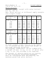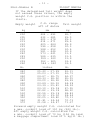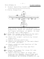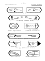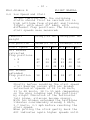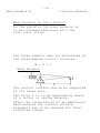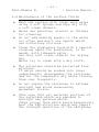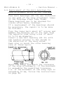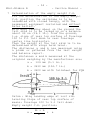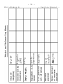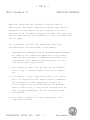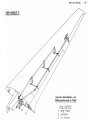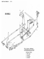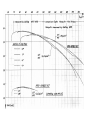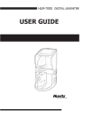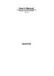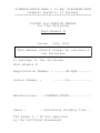
1
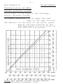
SCHEMPP-HIRTH GmbH & Co KG, KIRCHEIM-TECK Federal Republic of Germany ========================================= FLIGHT and SERVICE MANUAL for the Sailplane Mini-Nimbus B Issue: July 1979 This Manual should always be carried in the Sailplane It belongs to the Sailplane Mini-Nimbus B Registration Number : ......VH-FQB........ Serial Number : ......29............ Manufacturer: ...SCHEMPP-HIRTH............ Owner : ...Balaklava Gliding Club... The pages 5 - 38 are approved by the Luftfahrt-Bundesamt This page intentionally left blank - 1 Mini-Nimbus B FLIGHT MANUAL Table of Contents ================= Amendments 1 General 2 Operating Limits Page 2.1 2.2 2.3 2.4 2.5 2.6 2.7 2.8 2.9 2.10 Airspeeds Airworthiness Category Load Factors Weights Cockpit load C.G. Positions Weak links for Towing Minimum Equipment Acrobatics Wing and Tail Setting Control Surface Movements 5 7 7 8 8 10 12 12 13 13 14 3 Emergencies 15 3.1 3.2 3.3 Recovery from Spins Malfunction Canopy Jettison 15 15 16 4 Normal Operating Conditions 4.1 4.2 4.3 4.4 4.5 4.6 4.7 4.8 4.9 4.10 4.11 4.12 Daily Inspection Cockpit Lay-out Check before Takeoff Takeoff Free Flight Slow Speed Flight, Stalls High Speed Flight Flight with Water Ballast Cloud Flying Flights below Ice Point Acrobatics Approach and Landing 3 4 5 17 19 26 26 28 30 31 32 34 34 35 37 - 2 Mini-Nimbus B Maintenance and Service Manual Table of Contents 5. Page Storage, Transport, Assembly 5.1 Storage, Parking, Ground Towing 5.2 Assembly 5.3 Disassembly 39 40 42 6. 6.1 6.2 6.3 6.4 6.5 6.6 6.7 43 45 47 48 49 49 51 6.8 6.9 6.10 6.11 7. Maintenance Periodic Inspections Annual Inspections Backlash of Controls Backlash of Attachments Damages Tow Release Hook Weights and Hinge Moments of the Control Surfaces Maintenance of Surface Finish Replacement of Wing Attachment Bearings Safety Belts Instruments 53 54 55 55 Determination of the Empty 56 Weight and Gross Weight C.G. Position Weight and Balance Log Sheet 58 Inspection program for extension of service time 58a/b Exploded Views of Flight Controls and Attachments 59 Appendix Polar Curves Repair Instructions for FRP-Sailplanes November 1985 - 3 Mini-Nimbus B FLIGHT MANUAL Amendments - 4 Mini-Nimbus B FLIGHT MANUAL 1 GENERAL The Mini-Nimbus B is a single seat 15 m flapped sailplane in all fiber-glass construction. W i n g The cantilever two-piece wing has a double trapezoidal shape. It is built as a FRP-foam-sandwich shell with spar caps of parallel glass fibers and shear webs of FRP-foam-sandwich. The trailing edge air brakes are a combination of spoilers and flaps. The ailerons have internal drive. Two integral water tanks have a total capacity of 125 liters, serial no. up to 83. F u s e l ag e The fuselage is necked behind the wing. The one-piece canopy is faired into the fuselage and hinged at the right hand side. The fuselage shell is built in a pure glass-fiber lay-up and therefore has a high energy absorption. The fuselage shell is stiffened by FRP-foam-sandwich bulkheads The pilot is seated in a semireclined position. The landing gear wheel is retractable. A towing hook is installed as standard just in front of the landing wheel. Horizontal Tail Plane The horizontal tail plane is of a T-type with stabilizer and elevator. The elevator is trimmed by a spring loaded click-stop device on the flap operating rod in the cockpit. The stabilizer is built in a FRP-foam-sandwich, the elevator in pure FRP Vertical Tail Plane Fin and rudder are built in a FRP-foamsandwich construction. The rudder has an internal drive. - 5 Mini-Nimbus B 2 FLIGHT MANUAL OPERATING LIMITS 2.1 Airspeed limits (IAS) km/h knots mph Maximum speed Flap pos. -4, -7 VNE 250 135 155 Maximum speed Flaps pos. 0, + 8 VFE 180 97 112 In strong turbulence VB 200 108 124 Maneuvering speed VA 200 108 124 Airplane tow VAT 180 97 112 Auto-winch tow VWT 150 81 93 Note At increasing altitudes the true airspeed (TAS) is higher than the airspeed indicated on the ASI (IAS). This has no influence on the strength and loading capacity of the sailplane. For reasons of flutter safety however the following indicated airspeeds should not be exceeded. m Altitude ft. 0 3 000 6 000 10 000 0 9 800 19 700 32 800 VNE IAS IAS km/h knots 250 250 223 177 135 135 120 96 IAS mph 155 155 139 110 - 6 Mini-Nimbus B FLIGHT MANUAL Pressure error (at MSL) Dynamic pressure intake Pitot tube in the nose of the fuselage. Static pressure intake Airspeed Indicator: 15 cm under the rear edge of the spar cut-out. Variometer: In the area of the instr. panel and at the rear portion of the fuselage about 0.9 m in front of the vertical tail plane. Note: All speeds stated in this Manual are indicated airspeeds (IAS). - 7 Mini-Nimbus B FLIGHT MANUAL 2.2 Airworthiness Category U (Utility) according to the LFMS Based on the Airworthiness Requirements LFSM full control movements can be applied up to the maneuvering speed V A. At higher speeds it is possible to overstress the sailplane, therefore full control movements are not allowed at speeds exceeding 200 km/h, 108 knots or 124 mph. At the maximum airspeed VNE = 250 km/h, 135 knots or 155 mph a maximum of one third of the full control movement is permitted. The elevator control movement at V NE must be even less which depends on the permitted maneuvering load factor. Under normal weather conditions this sailplane can be safely flown at high speeds up to VNE = 250 km/h, 135 knots or 155 mph. In strong turbulence, i.e. in wave rotors, thunder clouds, visible upcurrents, or when flying over mountain ridges, the airspeed VB = 200 km/h, 108 knots or 124 mph must not be exceeded. 2.3 Load Factors The following load factors should not be exceeded: + 5.3 / - 2.65 at speeds of | 200 km/h,108 knots, 124 mph | air brakes + 4.0 / - 1.5 at speeds of | closed 250 km/h, 135 knots, 155 mph| + 3.5 air brakes extended The safety factor then is j = 1.5 - 8 Mini-Nimbus B FLIGHT MANUAL 2.4 Weights Maximum takeoff weight 450 kg, 992 lb. Max. weight of non-lifting parts 230 kg, 507 lb. Max. weight of water ballast (kg or liters) see page 9. 2.5 Loading instructions Cockpit load (pilot and parachute) Max. 110 kg, 243 lb. Min. 70 kg, 154 lb. The maximum takeoff weight must not be exceeded. Less weight than 70 kg, 154 lb. must be compensated with ballast (lead or sand cushion) on the seat, safely attached, e.g. onto the suspension of the seat belt. C.G. arm of the pilot incl. parachute or back cushion 550 mm, 21.65 inches ahead of datum. - 9 Mini-Nimbus B FLIGHT MANUAL (Serial Nr. up to 82) Water ballast Maximum takeoff weight with water ballast 450 kg, 992 lb. Max. water ballast at different empty weights and cockpit loads: Cockpit kg load Empty weight kg 220 230 240 250 260 Cockpit lb. load Empty weight lb. 485 507 529 551 573 70 80 90 100 110 lit. 125 125 125 125 120 lit. 125 125 125 120 110 lit. 125 125 120 110 100 lit. 125 120 110 100 90 lit. 125 110 100 90 80 154 176 198 220 243 lit. 125 125 125 125 120 lit. 125 125 125 120 110 lit. 125 125 120 110 100 lit. 125 120 110 100 90 lit. 125 110 100 90 80 At high cockpit loads care is to be taken not to exceed the max. permitted weight of non-load carrying structure. The baggage compartment can be loaded with a weight of max. 15 kg, 33 lb. of which only 5 kg, 11 lb. are allowed to be removed. The weight of objects which do not belong to the originally installed equipment must be considered when determining the maximum permitted water ballast. - 10 Mini-Nimbus B FLIGHT MANUAL 2.6 C.G. Range ========== a) C.G. range in flight (gross weight C.G.) +220mm(+8.66in.) to +380 mm(+14.96 in.) at all weights. Datum Wing leading edge at root rib. Leveling means Slope of rear top surface of fuselage: 100 to 5.1 tail down, i.e. main landing gear wheel on the ground and tail skid jacked up about 49 cm (19.3 in.). Be cautious not to exceed the permitted aft C.G. position. When a minimum cockpit load (pilot and parachute) of 70 kg (154 lb.) is observed, it is certain to be within the limits. Less weight is to be compensated with ballast on the seat (see page 8). b) Empty weight C.G. range After repair work, installation of additional equipment, new painting etc. the empty weight C.G. position must be checked. If it should not be within the limits, compensating weight must be added. If the limits of the empty weight C.G. are followed, it is certain that the gross weight C.G. is also within the permitted range. To facilitate the checking of the empty weight C.G. position the following table shows besides of the C.G. range for different empty weights also the max. permitted tail weight, calculated for the corresponding aft empty weight C.G. position. - 11 Mini-Nimbus B FLIGHT MANUAL If the determined tail weight does not exceed these values, the empty weight C.G. position is within the limits. Empty weight kg 200 205 210 215 220 225 230 235 240 245 250 255 260 lb. 440 450 460 470 480 490 500 510 520 530 540 550 560 570 C.G. range aft of datum mm 644 - 693 633 - 685 623 - 678 614 - 671 605 - 664 596 - 658 588 - 652 581 - 646 573 - 641 566 - 635 559 - 630 552 - 625 546 - 620 inches 25.40 25.03 24.67 24.33 24.00 23.69 23.39 23.10 22.82 22.56 22.30 22.05 21.81 21.58 - 27.29 27.01 26.75 26.50 26.26 26.03 25.81 25.59 25.39 25.19 25.00 24.82 24.64 24.47 Tail weight kg 28.7 29.0 29.3 29.6 29.9 30.3 30.6 30.9 31.2 31.5 31.9 32.2 32.5 lb. 63.11 63.73 64.37 65.01 65.65 66.29 66.93 67.55 68.20 68.83 69.46 70.11 70.73 71.37 Forward empty weight C.G. calculated for a max. cockpit load of 110 kg (243 lb.). Aft empty weight C.G. calculated for a min. cockpit load of 70 kg (154 lb.)and a baggage compartment load of 5 kg(11 lb.) - 12 Mini-Nimbus B FLIGHT MANUAL 2.7 Weak links for towing Winch and Airplane tow max. 600 ± 30 kg (1320 ± 66 lb.) 2.8 Mimimum Equipment Airspeed Indicator with a range of min. 50 km/h to min. 270 km/h min. 27 knots to min. 146 knots min. 31 mph to min. 168 mph marked as follows: km/h knots mph White Arc 77-180 41-97 48-112 flaps 0, +8 Green Arc 77-200 41-108 48-124 normal range Yellow Arc 200-250 108-135 124-155 warning range Red Radial 250 135 155 max. speed Yellow Arrow 85 46 53 approach Altimeter Four-piece safety belt Manual or automatic parachute or back cushion, compressed 10 cm (4 in.) thick. Placards (see pages 23 - 25) Flight and Service Manual For Cloud Flying (additional to the minimum equipment) Magnetic Compass, Variometer, Turn & Bank. The installed ASI system was found to be suitable for cloud flying. - 13 Mini-Nimbus B FLIGHT MANUAL 2.9 Acrobatics The Mini-Nimbus B is approved for the following acrobatic maneuvers: recommended entry speeds km/h knots mph Inside loops Spins Turns Lazy eight 200 60 200 180 108 32 108 97 124 37 124 112 It is recommended to install a recording accelerometer in addition to the equipment listed under 2.8. Acrobatic maneuvers are permitted only without water ballast. Loose objects are to be removed. 2.10 Wing and Tail Setting Reference: Rear fuselage center line. Angle of wing setting 0.70 Angle of tail setting 00 Control surface movements See page 14. Pay attention to the tolerances if repair work should be necessary. FLIGHT MANUAL - 14 - CONTROL SURFACE MOVEMENTS Mini- Nimbus B - 15 Mini-Nimbus B FLIGHT MANUAL 3 EMERGENCIES 3.1 Recovery from a Spin If the sailplane with the C.G. in medium or aft positions enters unintentionally into a spin ease the control stick forward immediately and apply opposite rudder until rotation ceases. It is very important to ease the control stick forward in order to avoid a rotation to the opposite direction when applying opposite rudder. 3.2 Malfunction Takeoffs by winch or airplane tow on uncutted grass fields should not be conducted. If a wing is caught in the grass release immediately to avoid a ground loop and therewith damage. To prevent the sailplane from unintentional and unnoticeable stall in an emergency release in low altitude a speed of 85 to 90 km/h, 46 to 49 knots or 53 to 56 mph (depending on the wing loading and flap position) should be maintained in a straight flight. In a turning flight the speed is to be increased corresponding to the angle of bank. If slight oscillations are observed or if the controls become spongy the sailplane is stalled though the ASI indicates 65 to 85 km/h, 35 to 46 knots or 40 to 53 mph (dependent on the wing loading and flap position). The control stick then is to be released forward immediately. - 16 Mini-Nimbus B FLIGHT MANUAL 3.3 Emergency Exit The roomy and well faired cockpit warrants a quick and safe bailing out in emergency. Jettisoning of the Canopy 1. PULL BACK the red ball knob at the left-hand side of the canopy frame. 2. PULL BACK the red ball knob at the right-hand side of the cockpit just below of the side fairing. 3. Throw off the canopy. The cord which holds the opened canopy in place is attached such to rip immediately when throwing off the canopy. The canopy frame on the fuselage is built of strong glass fibers without sharp edges and is well suited as a support for the pilot to jump off. - 17 Mini-Nimbus B FLIGHT MANUAL 4 Normal Operating Conditions =========================== 4.1 Daily Inspection 1 a) b) c) d) e) 2 When going around the sailplane for inspection, check all external surfaces for tears, blisters, or dents. In case of doubt ask a FRP-expert. Open the canopy and check if the main bolt is installed and secured. Check the cockpit controls by visual inspection Remove foreign particles. Check tire pressure of the main wheel (3.5 Atm. (50 psi). Check condition and function of the towing hook. Check ailerons for free and full movement. 3 a) Check air brakes for close fit and proper operation. b) Check trailing edges of flaps and ailerons for damage. Check flaps and ailerons for excessive backlash of attachments by rocking slightly at the - 18 Mini-Nimbus B FLIGHT MANUAL trailing edge. c) Check the function of the gas spring with flaps in position -7. Push the flaps down at the inner root into neutral position and then release. The flaps must return to the initial position -7. d) Check hinges for damage. e) Check if the holes for static pressure intake under the wing are open. 4 a) Check if the holes for static pressure intake in the rear fuselage shell are open. b) If available install the venturi and check the tubing by blowing into the venturi (the connected variometer must indicate "Climb"). 5 Check if the attachment of the horizontal tail plane is locked. 6 7 8 9 Check elevator and rudder for free and full movement, trailing edges for damage, attachments for excessive backlash by rocking slightly at the trailing edge. See 3 See 2 Check the pitot tube for contamination. When blowing into the tube the ASI must work. After heavy landings or excessive acceleration the frequency of flexural wing vibration should be checked (about 141/min.). Check also the elevator drive fitting on the horizontal tail plane for tears using a fivefold magnifying lens. If necessary the fitting should be replaced, - 19 Mini-Nimbus B FLIGHT MANUAL Disassemble the sailplane and check surfaces of fuselage, wing, and horizontal tail plane. If damages should be observed, e.g. tears in the painting of the rear fuselage and of the horizontal tail plane, white spots at the spar stubs or at the root ribs in the area of bearings and attachment bolts, deformation of the main bolt and of the elevator control fittings etc. The sailplane is unserviceable until the damages are properly repaired. 4.2 Cockpit Layout 1. Instrument panel With canopy opened the instruments are well accessible. The instrument compartment cover is fastened by four screws. The instrument panel is attached onto the fuselage canopy frame and is easy to remove. 2. Control stick The main landing wheel brake lever is mounted on the control stick. 3. Tow release The yellow handle at the left-hand side of the control stick operates the towing hook. - 20 Mini-Nimbus B FLIGHT MANUAL 4. Air brakes Extension: Pull back the blue handle at the left-hand side of the cockpit. Retraction: Push the handle forward. 5. Wing flaps Tilt the grey handle at the left-hand side of the seat inward and choose the desired position. High speed: Push the handle forward and catch it. Low speed: Pull back the handle and catch it. 6. Trimming control The spring loaded trimming control (green knob) is mounted onto the flap control rod at the left-hand side of the cockpit. It is gradually adjustable. Tilt the knob slightly inward, choose the position and lock. Nose heavy : Push forward. Tail heavy : Pull back. 7. Canopy The one-piece plexiglass hood is attached by flush hinges at the right-hand side of the fuselage. It is opened at the left-hand side of the cockpit. PULL BACK the red ball knob of the locking device on the canopy frame and lift the canopy. Take care that the cord which holds the opened canopy in place is attached. The jettisoning device is mounted at the right-hand side of the cockpit, just under the side fairing. - 21 Mini-Nimbus B FLIGHT MANUAL For jettisoning open the canopy as described before, then PULL BACK the red ball knob. 8. Landing gear RETRACTION : Unlock the black handle at the right-hand side of the seat, pull it back and lock. EXTENSION : Push the handle forward and lock. 9. Water ballast Black knob at the right-hand side of the cockpit, just under the side fairing. Knob in aft position: Dump valve closed. Knob in front position and locked: Dump valve open. 10. Pedal adjustment The adjustment device is operated by a Bowden cable with a plastic T-handle at the right-hand side of the control stick. Adjustment backward: Pull the cable and move the pedals into the desired backward position. Give the pedals a slight forward push with the heels, not with the toes, until the locking pin engages self-acting with a clear clicking noise. Adjustment forward: Pull the cable slightly back to unlock the mechanism and push the pedals with the heels into the desired forward position and lock as before. 11. Parachute support A molded glass fiber support, serving as a stowage recess for automatlc back-type parachutes, is attached onto the rear - 22 Mini-Nimbus B FLIGHT MANUAL part of the seat by means of four screws. When using a manual long back-pack parachute it is advisable to take it off. 12. Cockpit ventilation The ventilator is closed by pulling the small black knob at the right-hand side of the instrument panel. In addition the sliding window of the canopy or its air scoop can be opened. - 23 Mini-Nimbus B FLIGHT MANUAL 13. Cockpit Placards Identification plate (fire-proof) Hersteller: SCHEMPP-HIRTH KIRCHHEIM-TECK Bau-Muster Werknummer T.C. No. Operating limits Max. take-off weight 450 kg, 992 lb. Maximum permitted speeds (I.A.S.) Flaps: Positions -4 or -7 Positions 0 or +8 In strong turbulence Maneuvering speed Airplane tow Auto and winch tow km/h knots mph 250 180 200 200 180 150 135 97 108 108 97 81 Altitude VNE (IAS) m ft. km/h knots mph 3000 9800 250 135 155 6000 19700 223 120 139 10000 32800 177 96 110 Weak links for towing 600 ±30 kg, 1320 ±66 lb. Landing wheel tire pressure 3.5 Atm., 50 psi 155 112 124 124 112 93 - 24 Mini-Nimbus B FLIGHT MANUAL Cockpit load Payload (pilot and parachute) The maximum weight must not be exceeded. Minimum payload: 70 kg, 154 lb. Less weight must be compensated with ballast on the seat. Check List before take-off Parachute put on properly? Strapped. in safely? Back rest and rudder pedals in comfortable position? Operating handles and instruments well accessible? Air ~brakes locked after having checked the function? Movement of control surfaces checked? Flight controls unrestricted? Trim adjusted properly? Wing flaps in take-off position? Canopy closed and locked? The following acrobatic maneuvers are permitted: recommended km/h knots mph entry speed Inside loops 200 108 124 Spins 60 32 37 Turns 200 108 124 Lazy eight 180 97 112 - 25 Mini-Nimbus B FLIGHT MANUAL Extended Landing gear Retracted Trimming (GREEN knob) Pedal adjustment Tow release (YELLOW T-handle) Air brakes (BLUE handle) OPENING JETTISONING Canopy (RED ball knobs) Ventilation Water ballast - 26 Mini-Nimbus B 4.3 FLIGHT MANUAL Check before take-off See cockpit placard on page 24. 4.4 Take-off Aerotow Maximum permitted speed on aerotow: VT = 180 km/h (97 kt, 112 mph). Use the C/G hook for aerotow or, if installed, the nose tow hook. The Mini-Nimbus has been aerotowed using Nylon ropes of between 40 and 60 m length (130-200 ft). When commencinq the ground run apply the wheel brake gently so that the sailplane does not overrun the tow rope. For take off set flaps at "-4" and the trim to "neutral" for forward to middle C.G. positions, or to "nose heavy" for middle to aft C.G. positions. With the C.G. in a middle to forward position, the elevator should be neutral for the groundrun; in the case of rear C.G. positions it is recommended that down elevator is applied until the tail lifts. As the speed increases select flap setting "0". With middle to rear C.G. positions the sailplanes leaves the ground at "0" flap setting, and in the case of forward C.G. positions or if the all-up weight is high, flap setting "+8" should be selected to shorten the take-off run. After the sailplane left the ground, at speeds of about 70 to 75 km/h (38-40 kt, 43-47 mph), the trim can be set for minimum control stick loads. Normal towing speed is in the region of 100 to 120 km/h (54-65 kt, 62-75 mph) with flap setting "0". At speeds in excess of 120 km/h (65 kt, 75 mph) the appropriate flap setting is "-4". When water ballast is carried the normal towing speed should be increased by up to 15%. TECHNICAL NOTE NO. 328 - 7 November 1985 - 27 Mini-Nimbus B FLIGHT MANUAL The undercarriage may be retracted during the aerotow; this is not, however, recommended at low altitude, as changing hands on the control stick could easily cause the sailplane to lose station behind the tug. When releasing the rope, pull the yellow cable release handle fully several times and confirm that you have released successfully before turning. Winch launch Maximum permitted winch launch speed : VW = 150 km/h (81 kt, 93 mph). For winch launching only the C/G hook must be used. The flaps are set at "0" (or at "+8" if the all-up weight is more than 400 kg/882 Ib). Before taking-off the trim should be set to "neutral" for forward to middle C.G. positions or to "nose heavy" for middle to aft C.G. positions. AS the cable tightens, apply the wheel brake gently to prevent the sailplane overrunning the cable. Ground run and take-off are normal - there is no tendency to climb excessively steeply on leaving the ground. At the moment of lift-off, depending on the C.G., the control stick should be held in a well forward position (in the case of aft C.G. positions) or slightly pulled back (in case of forward C.G. positions). After climbing gently to a safety height of about 50 m (164 ft), the transition to a typical winch launch climbing attitude is effected by easing the control stick back. If pitching motions occur during the last stage of the tow, ease the control stick slightly forwards. Climbing take-offs and low towing speeds must be avoided. TECHNICAL NOTE NO. 328 - 7 November 1985 - 28 Mini-Nimbus B FLIGHT MANUAL With normal cockpit load and without water ballast the towing speed should not be less than 90 km/h, 49 knots, 56 mph, with water ballast not less than 100 km/h, 54 knots, 62 mph. When using low-powered winches or engines with limitation of RPMs, when towing with the wind, in calm air or with filled water ballast tanks make sure that the winch has enough power reserve to maintain the required minimum towing speed. Normal towing speed km/h knots mph without water ballast 100 54 62 with water ballast 115 62 71 When reaching the maximum towing height the tow rope is released automatically, nevertheless pull the release handle several times. 4.5 Free Flight Test the effectiveness of the air brakes in safe altitude, observe the loss of height at different speeds and get familiar with the operation of the wing flaps. Since the trim is combined with the flaps it is to be adjusted for zero stick force in straight flight with flaps in position O. The sailplane then is trimmed for all other flap positions over the optimum speed range (except of high speeds). The sailplane has well balanced flight characteristics and controls. With flaps in position 0 and at a speed of 1.4 Vstall the time taken to roll from a 45 degr. banked turn through an angle of 90 degrees is 3 seconds. - 29 Mini-Nimbus B FLIGHT MANUAL Flight performances (W/S = 33 kg/m², 6.76 lb./sq.ft.) Stall speed (flap position +8) 61 km/h, 33 knots, 38 mph Minimum sink (flap position +8) 0.57 m/sec, 1.87 ft./sec. at 80 km/h, 43 knots, 50 mph Best gliding ratio 1 : 41 at 95 km/h Max. L/D 51 knots, (flap position 0) 59 mph Wing flaps The flaps have the purpose to adapt the laminar bucket of the wing airfoil to the respective airspeed in the best way. Since the laminar buckets of the applied airfoil are covering eachother widely, the following flap positions can be accepted: Normal flight - four positions Landing - one position High speed flight - one position Application Flaps Approach +8 Thermal flight +8 Best glide Flight between thermals High speed Airspeed km/h knots mph see page 37 70-90 38-49 43-56 0 80-120 43-65 50-75 -4 110-170 59-92 68-106 -7 160-250 86-135 99-155 With water ballast the speeds increase about 15 %. - 30 Mini-Nimbus B FLIGHT MANUAL 4.6 Low Speed and Stall To get familiar with the sailplane stalls should first be carried out in high altitude from straight and turning flight, with about 45° bank, with different flap positions. The following stall speeds were measured: Take-off weight 335kg(739 lb.) 450kg(992 lb. C.G.position 380mm(15 in.) 220mm(8.7in.) km/h knots mph km/h knots mph Stall speed air brakes retracted flap positions + 8 62 33 38 75 40 47 0 67 36 42 81 44 50 - 7 77 42 48 89 48 55 air brakes extended flap position + 8 58 31 36 68 37 42 Shortly before reaching the stall speed stall warning occurs with air brakes retracted at speeds of 62 to 89 km/h, 33 to 48 knots, 38 to 55 mph (depending on the wing loading and flap position) by slight vibration of the horizontal tail plane, ailerons become spongy. With air brakes extended the sailplane vibrates considerably already 5 km/h, 2.7 knots, 3.1 mph before reaching the stall speed. When pulling the stick gently back the ASI indicates again higher speeds until - 31 Mini-Nimbus B FLIGHT MANUAL (with the C.G. in aft positions) control is lost by wing dropping or (with the C.G. in forward positions) the sailplane pancakes when the control stick reaches the limit of backward travel. The control stick then is to be eased forward. With air brakes extended the loss of height during recovery to normal flight is about 50 m, 164 ft. With the C.G. in aft positions full rudder in a stall brings the sailplane into a spin. It recovers safely from the spin by the standard method which is defined as: a) apply opposite rudder (i.e. against the direction of rotation of the spin) b) pause; c) ease the control stick forward until the rotation ceases and the sailplane becomes unstalled; d) neutralize the rudder and allow the sailplane to dive out. 4.7 High Speed Flight When flying at high speed observe the maximum limiting speeds for the respective flap positions as marked on the ASI by corresponding colors. Full control movements are permitted at speeds up to VA = 200 km/h, 108 knots, 124 mph only. At a speed of VNE = 250 km/h, 135 knots, 155 mph only one third of the full control movements is allowed. Avoid sharp elevator control movement in any case. In strong turbulence, e.g. in wave rotors, thunder clouds, visible vertical whirlwind or when flying over mountain ridges - 32 Mini-Nimbus B FLIGHT MANUAL the speed must not exceed VB = 200 km/h, 108 knots, 124 mph. With the C.G. in aft positions the required stick travel at all speeds up to VNE is relatively small, the change of speed however is clearly noticed by a change of the stick force. The air brakes can be extended at speeds up to VNE = 250 km/h, 135 knots, 155 mph. Since sudden deceleration of about 2g can occur, the air brakes should be used only in emergencies or when exceeding unintentionally the maximum permitted speeds (see page 5). Take care that the safety belt and the shoulder harness have a tight fit. Do not push inadvertently the control stick when extending the air brakes. Avoid loose objects in the cockpit. With air brakes extended do not pull-out too rapidly but gently (see load factors page 7). Due to the steep flight attitude the air brakes should not be retracted at speeds exceeding 140 km/h, 76 knots, 87 mph. The terminal velocity in a dive with an inclination of the flight path of 45 0 is about 150 km/h, 81 knots, 93 mph, air brakes and landing gear extended. - 33a Mini-Nimbus B FLIGHT MANUAL 4.8 Flight with water ballast When an average climbing speed of less than 1.5 m/sec., 3 knots or 5 ft./sec. is expected or when flying in narrow thermals where highly banked circling is required the use of water ballast is not worthwhile. Before filling water into the wing tanks the maximum permitted water ballast is to be determined following the instructions on page 9. The wing tanks have a total capacity of about 125 liter water. With wings held level the tanks are filled through a hole in the upper surface next to the station of the inboard aileron root. Do not fill under high pressure, e.g. directly from the water main. Both tanks must be filled with the same water quantity. Due to the installed baffles no noticeable shifting of the water is observed. The filling holes are closed by a cap which has a small 5 mm dia hole for pulling it out by means of the provided pin. The hole in the cap serves also as a vent hole and therefore must be kept open. The tanks have an additional vent by means of plastic tubing leading through the wing with outlet at the outboard aileron root. The water is drained off through a hole in the lower wing surface next to the root rib. With the dump valve operating knob at the right-hand side of the cockpit pushed back (dump valve closed) the connection of the water ballast system of the wing to the fuselage is made automatically when attaching wings. - 33b Mini-Nimbus B FLIGHT MANUAL Pushing the knob forward opens the dump valve in the wings, moving the knob down locks it in that position. When flying at temperatures lower than 0 degr.C (32 degr.F) the water must be drained off to avoid icing. Drain off the water before landing to reduce the approach speed and therewith the landing run. Full water tanks are drained off within about 4 minutes. In the improbable case that the water tanks should be unequally drained off or only one-sided, stalls are to be avoided and an adequate margin of safety in the lower speed range should be observed. When the glider with the C.G. in aft positions comes to stall yet and enters unintended a spin, set the flaps on negative position immediately, apply opposite rudder and ease the control stick forward. Dive out gently when rotation has ceased. During the landing run care is to be taken of the tendency for the glider to ground loop due to the earlier ground contact of the heavier wing. Never park the sailplane with filled water tanks, Drain off the water, open the caps and let the tanks dry. If the dump valves with filled water tanks should leak, coat the closing caps slightly with grease before the next filling; pull the cap down by means of a M6 mm bolt screwed into the threaded hole in the center of the cap. This page intentionally left blank - 34 Mini-Nimbus B FLIGHT MANUAL 4.9 Cloud flying The sailplane has sufficient strength and stability for cloud flying. It is easy to control and has stable circling qualities. Nevertheless observe the following instructions: Do avoid extreme airspeeds in any case. To prevent the sailplane from a spiral dive do not execute spins as a rescue action. It is recommended to extend fully the air brakes already at an indicated speed of 130 km/h, 70 knots, 81 mph or at a load factor exceeding 2g. At speeds exceeding 140 km/h, 76 knots, 87 mph the air brakes should not be retracted again, due to its steep attitude the sailplane then could exceed the maximum permitted speed. Take care that the required equipment for cloud flying is installed in the sailplane (see page 12). 4.10 Flight below freezing point At temperatures below 0 degr.C (32 degr.F) as in wave flights or during winter it is possible that the flight controls cannot be operated with sufficient ease and smoothness, therefore all controls should be free from moisture to avoid icing. - 35 Mini-Nimbus B FLIGHT MANUAL This, in particular, applies to the AIR BRAKES. Experiences have shown that it is very advantageous to coat the full span of the top covers on the air brakes with Vaseline to avoid jamming by icing. Flaps and control surfaces are to be moved frequently. When flying with water ballast observe the instructions on page 33. 4.ll Acrobatics (without water ballast only) Inside loops, flaps in position -7° The maneuver should be entered at speeds not less than 180 km/h, 97 knots, 112 mph. A speed of 200 km/h, 108 knots, 124 mph is recommended. The speed during recovery is 180 km/h, 97 knots, 112 mph. Spins, flaps in position +8° or 00 Steady spins are possible only with the C.G. in the aftmost position. With the C.G. in forward positions the sailplane goes into a spiral dive. Recovery then must be initiated immediately by neutralizing all controls and diving out. Entry to the spin is initiated from dynamic stall by applying rudder in the direction of rotation just before stalling out.(Ailerons neutral). Speed during entry to the spin: 60 km/h, 32 knots, 37 mph. Speed during recovery from the spin: 120-150 km/h, 65-81 knots, 75 - 93 mph. Action for recovery from the spin is initiated by applying opposite rudder and easing the control stick forward. - 36 Mini-Nimbus B FLIGHT MANUAL Turns, flaps in position -7° Entry to the turn at speeds not less than 180 km/h, 97 knots, 112 mph. A speed of 200 km/h, 108 knots, 124 mph is recommended. After entry to the turn apply rudder in the vertical climb at a speed of 130 km/h, 70 knots, 81 mph. Speed during recovery from the turn: 180-200 km/h, 97-I08 knots, 112-124 mph. Lazy Eight Entry to the maneuver at a speed of 180 km/h, 97 knots, 112 mph, followed by a climb of about 30 to 45 degrees from which a turn is initiated at a speed of 120 km/h, 65 knots, 75 mph. Speed during recovery: 180 km/h, 97 knots, 112 mph. Dependent on the load factor and the angle of bank the speed in steep turns should not be less than the values given in the following table: Load factor + + + + 2.0 2.5 3.0 3.5 Angle of bank 600 650 70o 73° km/h 110 125 135 150 Speed knots 59 67 73 81 mph 68 78 84 93 Acrobatics are permitted only when flying without water ballast. - 37Mini-Nimbus B FLIGHT MANUAL 4.12 Approach and Landing The very effective air brakes are a combination of spoilers and flaps and allow steep and slow approaches. They do not notably increase or decrease the lift. The normal flap position during the landing is +8. Pulling back the air brake handle until a clear resistance is observed means extending only the spoilers by which the sailplane can be controlled during the approach. When pulling the handle further back the spoilers and flaps are cooperating. The normal approach speed is about 75 - 80 km/h, 40 - 43 knots, 47 - 50 mph with flaps in position +8, air brakes and landing gear extended. With water ballast the speeds increase up to 15%. The gliding angle is about 1 : 4.5. In the approach pull-out arc or shortly before landing at speeds less than 70 km/h, 38 knots, 43 mph the air brakes must not be slowly retracted but rapidly and fully, otherwise only the flaps are taken back into normal position (loss of lift) while the spoilers with their full drag and decrease of lift are still fully extended. Rapid and full retraction of the air brakes does not considerably change the lift and longitudinal inclination of the sailplane; the sinking speed resp. the gliding angle however promptly improve. - 38 Mini-Nimbus B FLIGHT MANUAL With semi-retracted air brakes the Mini-Nimbus pancakes. Landings always should be carried out with fully extended air brakes, for this configuration ensures the lowest touch down speed. Steep approaches (e.g. in strong ground turbulence or over high obstacles) should be made with fully extended air brakes while the gliding angle is corrected with elevator control only. Excessive height can be reduced without gaining much speed by easing the control stick forward. The sailplane touches down on the landing wheel and the tail skid simultaneously. The wheel brake (drum brake) is sUfficiently effective. The brake lever is mounted onto the control stick. To avoid a long landing run it is advisable to touch down at a minimum speed of 60 - 65 km/h, 32 - 35 kts, 37-40 mph. Touching down at 90 km/h, 49 knots, 56 mph instead means doubling the energy of the sailplane and considerably increases the running distance. Landings have been demonstrated with cross winds up to 20 km/h, 11 knots, 12 mph. When off-field landings are inevitable always extend the landing gear. Flying in rain or with iced-up wings means a loss of performance and aerodynamic qualities. Therefore be cautious when landing! Come in at a speed of about 95 - 100 km/h, 51 - 54 knots, 59 - 62 mph. - 39 Mini-Nimbus B - Service Manual - 5 Storage, Transport, Assembly ============================ 5.1 Storage, Parking, Ground towing The sailplane should be stored or parked in well ventilated rooms. Closed weatherproof trailers should be equipped with sufficiently large vent holes. Store or park always with fully drained off water tanks. Take care to keep the sailplane free from any strain, especially at higher temperatures. Due to their high fineness ratio the wings with leading edge down must be supported very carefully at the center of the spar stubs and in a section-true wing support at a distance of about 2.4 m from the tip. The fuselage should be supported on a wide cradle just in front of the C.G. towing hook and on the tail skid. The horizontal tail plane is to be supported with leading edge down on section-true cradles which should have a distance of about 1.5 to 2.0 m. In trailers the horizontal tail plane must not be supported at the attachment fittings. Sailplanes which are kept assembled for longer periods must be maintained so to avoid corrosion of the attachments of the fuselage, wings and tail surfaces. The use of dust covers on high performance sailplanes should be taken for granted. When towing the sailplane by car always use a tail dolly to avoid excessive stress and therewith wear of the tail plane attachments due to vibration. - 40 Mini-Nimbus B - Service Manual - When towing off by hand do not push at the wing tips but at the wing root area. 5.2 Assembly Wings. 1) Clean and lubricate the attachment bolts and bearings. 2) Adjust the flap control lever in the cockpit on "high speed" position -7°, the air brake control lever and the dump valve operating lever on position "CLOSED". 3) Put the left wing (fork spar root) with the flap in position -70 and lifting it slightly into the cut-out of the fuselage up to a distance from the fuselage of about 1 cm, unlock the air brake control lever, push the wing fully in and insert the main bolt into the front fork spar bushing only. Be cautious that the bell cranks on the root rib are safely engaged into the funnel-type fittings on the fuselage and that the flap control is catching properly the torsion drive tube. The wing then can be laid down on a support (e.g. on the tail plane support). Lock the flap control lever in position 0° and extend fully the air brake. 4) Put in the right wing (tongue spar root) up to a distance from the fuselage of about 10 cm. Open fully the air brake. Push in the wing with aileron in neutral position while moving the wing tip slightly back and forth and lifting the trailing edge a little to avoid a tilting of the attachment bearings on the fuselage When a distance of 1 to 2 cm between wing root rib and fuselage is reached remove the main bolt. - 41 Mini-Nimbus B - Service Manual - Take the provided assembly tool, push it through the main bolt spar bushings and pull the wings together. Take care of the proper connection of the controls as described by the instructions No.3. 5) Push the main bolt through the aligned spar bushings and secure its handle onto the fuselage shell by means of a cowling safety pin. 6) Horizontal tail plane Screw the ring bolt (mounting aid provided in the side pocket of the cockpit) into the front attachment bolt on the fin. Put the horizontal tail plane onto the two control connection bolts, pull the spring-loaded front bolt by means of the ring andinsert the bolt into the bearing of the attachment fitting on the lower surface of the stabilizer. Remove the ring bolt. Check if the two control connection bolts are properly inserted into their bearings by moving the elevator. 7) After assembly Check the function of all controls. Seal the joints of the wing and fuselage with an adhesive tape. Seal also the hole in the fin for the front attachment bolt and the joint of stabilizer and fin. The sealing is very important to ensure good fight qualities. - 42 Mini-Nimbus B - Service Manual - 5.3 Disassembly 1) Horizontal tail plane. Pull the front attachment bolt using the ring bolt. Lift slightly the leading edge of the stabilizer and take off the tail plane in forward direction. 2) Wings. With air brakes unlocked and flaps in position 00 load the wings and pull out the main bolt. Disconnect the wing attachment by pulling thoroughly at the wing tips and take off the wings. - 43 Mini-Nimbus B - Service Manual - 6 Maintenance =========== 6.1 Periodic Inspections Rudder control cables After every 200 flight hours and at every annual inspection the rudder control cables are to be checked in the area of the S-shaped tubular guide on the pedals with pedals in front and aft position. The control cables should be replaced if injured, worn or corroded. A wear of single outer strands up to 25% is permissible. If a replacement of the cables should be necessary cables 3.2 mm (1/8") LN 9374 made of zinked carbon steel strands are to be used. The thimble eye-splices are made with Nicopress Oval Sleeves No. l8-3-M or No. 28-3-M using a tool No. 5l-M-850 and following the special instructions for making and checking the sleeves. Gas springs After removal of the upper fiber-glass fairing on the front steel tube frame the gas springs are accessible behind the front wing attachment tube. The piston rods must be clean and without any damage. If a leakage of the piston rod oil seal should be observed the gas spring must be replaced. The expansion force of the gas spring is to be checked on the assembled sailplane with flaps in position -70. It must be possible to hold the flap in this position without moving down when applying a moment of 16 to 19 Nm resp. 1.6 to 1.9 mkg or 11.6 to 13.7 ft.lb. - 44 Mini-Nimbus B - Service Manual - The required moment is obtained by pulling the trailing edge of the flap in the area of its root using a spring balance or by attaching weights. The force or the weight should be P = 7.0 to 8.5 kg or 15.4 to 18.7 lb. Towing hook Inspections are to be carried out in accord with the Operating and Maintenance Instructions for Special Towing Hooks "S 72 and SH 72", dated May 1975, LBAapproved. Instruments Follow the instructions of the respective manufacturers. Suppliers Schempp-Hirth GmbH & Co KG Krebenstr. 25, D - 7312 Kirchheim-Teck (Cables, Sleeves, Gas springs, Main landing wheel) R. Lindemann Osterrade 12, D-2050 Hamburg 80 (Nicopress sleeves, Tools) TOST Flugzeuggerätebau Thalkirchnerstr. 62, D-8000 München 2 (Towing hook) -45Mini-Nimbus B - Service Manual - 6.2 Annual Inspections Maintenance schedule (See control system views on pages 59, 60, 61). Accessibilty of controls for inspection: Wing controls Aileron drive accessible through cut-outs in the rear wing spar with air brake opened and aileron dismounted. Air brake drive accessible through cutouts in the rear wing spar with air brake opened. Fuselage controls Drives in the fuselage accessible after removal of the seat panel and the fairing on the front steel tube frame. Elevator control Accessible after disassembly of the horizontal tail plane. Rudder control Accessible through the cut-out in the nose with rudder deflected to the right. After having cleaned the sailplane proceed as follows: Check all external surfaces for holes, tears, scratches, dents, and detached laminates. If the outer laminate of a sandwich shell is damaged also the inner glass cloth layer is to be inspected. It is advisable to ask an expert's advice. Check all accessible metal parts for damage. As known from experience no damage occurs when operating the sailplane properly. - 46 Mini-Nimbus B - Service Manual - If any repair should be necessary ask the advice of the manufacturer. Check all accessible metal parts for corrosion. If necessary remove the rust and protect the surface again by a new painting. Corroded fittings, push rods, and levers should be thoroughly cleaned and consequently primed and painted, using a special primer and Nitro paint (primer and paint can be supplied by Schempp-Hirth. If the controls cannot be operated with sufficient ease and smoothness, clean and lubricate the corresponding hinges or bearings. Replace bearings which have an excessive radial clearance. The automatic connections of ailerons and air brakes between wing and fuselage can be adjusted free from backlash by correcting screws on the funnel-type levers of the fuselage. The backlash of controls and air brake drive is to be checked in accord with paragraph 6.3. All fittings attached onto glass-fiber structure are to be checked for a tight fit. Check the glass-fiber structure for tears, white spots, and broken glass cloth laminate. If a loss of the braking effect of the landing wheel is observed, clean the brake drum, inspect the brake lining, replace the lining if worn. Check the brake Bowden cable and the brake lever, adjust if necessary. Check the wheel hub for lateral clearance. Follow the instructions of the manufacturer TOST. Check the wheel axle and landing gear struts for deformation and the attachment fittings for damage. - 47 Mini-Nimbus B - Service Manual - Check the tire pressure of the main landing wheel (3.5 Atm. or 50 psi). Inspect the static and dynamic pressure intakes, the tubing, and couplings for free air pass and tightness. Check instruments for loose glasses. Assemble the sailplane and check the control surface movements and all controls for easy and smooth operation. The gap between flap, air brake and aileron should be at least 2 mm, 0.08 in. Check the wings and control surfaces for excessive backlash of controls and attachments (see paragraphs 6.3 and 6.4). Check the function of the tow release mechanism. 6.3 Backlash of the controls With controls held fixed the backlash of the control surfaces must not exceed the following values: Control surface Backlash Measuring point aft of hinge axis mm in. mm in. Elevator ±3 ±0.12 162 Rudder ±5 ±0.2 350 13.8 Flaps ±5 ±0.2 235 9.3 Ailerons ±4 ±0.16 136 5.4 *Air brakes ±2 ±0.08 *120 *4.7 6.38 *measured above hinge axis at fully opened air brake. - 48 Mini-Nimbus B - Service Manual - 6.4 Backlash of the attachments Wings Tangential backlash (movement forth and back) can occur, due to the wear of the washers which are pressed onto the wing attachment bolts. If the movement at the wing tips exceeds 30 mm (1 3/16") additional washers of an inner diameter of 13.95 mm about 0.3 to 0.5 mm thick should be pressed onto the bolts until the backlash is eliminated. - 49 Mini-Nimbus B - Service Manual - 6.5 Damages Before every take-off, especially after a longer period of storage, a ground inspection should be carried out (see Flight Manual, page 17). Pay attention to damages as tears in the paint, holes, white spots in glass-fiber laminate etc. In case of doubt about the seriousness of the damage ask the advice of a FRP-expert. Smaller damages which do not impair the airworthiness of the sailplane can be repaired by the owner himself. (See Appendix: "Repair Instructions"). 6.6 Tow release hook The tow release hook, mounted on the bottom of the fuselage just in front of the landing wheel, is much exposed to dirt and must be checked quite often for damages. Keep it clean and lubricated. It is easy to take off the tow release hook for inspection or repair. Remove the seat panel, disconnect the release cable and unscrew the two attachment bolts. In case of belly landings the towing hook is protected by two angular fittings which are bolted onto the attachment brackets of the hook. If these fittings show an abrasion up to the heads of the attachment bolts, they must be replaced. When mounting the towing hook again take care to attach it onto the bracket as shown on sketch, page 51. - 50 Mini-Nimbus B - Service Manual - Attachment of the tow release hook in front of the landing wheel Towing hook to be attached onto the bracket by the bolt holes 3 and 5. - 51 Mini-Nimbus B - Service Manual - 6.7 Weights and hinge moments of the Control surfaces After repair or a new painting the weight and hinge moment of the control surfaces must not exceed the following values: Control surface Flap Aileron Elevator Rudder Weight kg lb. 4.3 3.3 1.0 5.2 9.48 7.28 2.20 11.46 Hinge moment mkg ft.lb. 0.177 0.086 0.060 0.083 1.28 0.62 0.43 0.60 If these values are exceeded a mass balance must be installed in front of the hinge axis. Mass balance on flaps and ailerons A square bar of lead or of similar heavy material is to be attached onto the inside of the nose strip between the first and second hinge fittings by means of 4 mm or 5/32" counter sunk screws in a distance of 100 to 150 mm, 4 to 6 in. each. Mass balance on the rudder Parallel to the already installed round bar a square or round bar of the required weight is to be glued onto the inside of the nose strip and covered with a glass cloth layer. additional mass balance - 52 Mini-Nimbus B - Service Manual - Mass balance on the elevator On the elevator the mass balance is to be attached span-wise onto the nose joint strip. The hinge moments must be determined on the disassembled control surfaces. M = P • r Mass balance The control surface should be supported at its hinge axis. The force P is to be measured by means of a letter or spring balance. After the installation of an additional mass balance the control surface movements are to be checked for their inlimited travel. - 53 Mini-Nimbus B - Service Manual - 6.8 Maintenance of the surface finish Wash the surface with clean warm water using a soft sponge and wipe dry with a soft clean chamois. Never use gasoline, alcohol or thinner for cleaning. Do not add washing agents to the water too often and don't use agents which are containing Silicone. Clean the plexiglass hood with a special cleaning agent for plexiglass, or in needs, with lukewarm water. Use only soft clean chamois for wiping dry. Never try to clean with a dry cloth. The sailplane should be protected from moisture. If water should be soaked into inner compartments, disassemble the sailplane and let the components dry while turning them over frequently. Do not expose the sailplane to extreme sunlight and avoid unnecessary permanent strain. Take care that all external portions of the sailplane which are exposed to sunlight are painted white. Other colors than white would excessively heat the FRP-structure which may impair the strength qualities of the sailplane. - 54 Mini-Nimbus B - Service Manual - 6.9 Replacement of the ball bearings for wing attachment bolts on the fuselage Four ball bearings (GL 14) are installed at the ends of the wing attachment tubes of the fuselage steel tube frame. These bearings are to be checked for cracks after heavy landings. If a replacement of the bearings should be necessary, the repair is to be done as follows: Turn the inner ball about 90° across and hammer the bearing out of its seat from the opposite side using a bar of about 12 to 14 mm diameter. Insert a new ball bearing (GL 14) with the lead-in grooves to the inside in the direction of the wing chord. Peen over or punch the outer bearing race at three spots. Mount the wings and check the clearance of the wing attachments. If the backlash is exceeding the permitted tolerance, i.e. if the movement at the wing tips is exceeding 30 mm, follow the instructions on page 48. - 55 Mini-NIMBUS B - Service Manual - 6.10 Safety belts A four-piece safety belt is required. Following makes and models are approved: Seat belt Gadringer - Bagu IV-D or IV-E Autoflug - Bagu FAG - 7F/0 Attachment: Brackets on the fuselage shell and accessible through cut-outs in the seat panel. Shoulder harness Gadringer - Schugu II-C Autoflug - Schugu FAG - 7H/0 Attachment: Front wing attachment tube accessible through cut-outs in the upper FRPfairing. 6.11 Instruments The original certification of the Mini-Nimbus B was carried out using the following instruments: Airspeed Indicator 30- 300 km/h marked in accord with 2.8, page 12 Winter 6FMS 4-2 Altimeter 10-1000-10000 m Winter 4 FGH 10 Magnetic Compass, Ludolph FK 16 Variometer, Winter St V 5 Radio, Dittel FSG 40 S For the basic equipment or for cloud flying any approved instruments can be used, if they meet the requirements of 2.8, page 12. - 56 Mini-Nimbus B 7 - Service Manual - Determination of the empty weight C.G. For the determination of the empty weight C.G. position the sailplane is to be assembled with closed canopy, with the permanent equipment installed and without water ballast. With main landing wheel on the ground the tail skid is to be jacked up on a balance about 49 cm (19.3 in.) from the ground, i.e. slope of rear top surface of fuselage 100 to 5.1 tail down or rear fuselage center line horizontal. Then the weight at the tail skid is to be determined with wings held level. The distances a and b are measured using a plumb or gathered from the last weight and balance report. The distances a and b measured at the original weighing by the manufacturer are: a = 129 mm (5.1 in.) b = 3930 mm (154.7 in.) b = 3900 mm with tailwheel for FQB Datum : Wing leading edge at root rib. Leveling Slope of rear top surface of means: fuselage 100 to 5.1 tail down. Empty weight C.G. position: W2 • b x = + W a - 57 Mini-Nimbus B - Service Manual - The empty weight C.G. position must be within the limits given in the Table on page 11 of the FLIGHT MANUAL. A determination of the empty weight C.G. position is required after the installation of additional equipment, after repair or modifications which are changing the weight of the sailplane. Changes of weight and C.G. position are to be entered into the log book and confirmed by a designated inspector. Gross weight C.G. position Before conducting performance flights it is recommended to determine the true gross weight C.G. position in order to check if it is within the optimum range for high performance. Optimum gross weight C.G. range: 310 mm to 380 mm (12.2 in. to 15 in.) aft of datum. The sailplane is to be weighed as described on page 57 with pilot and parachute and additional equipment as seat cushion, barograph, cameras etc. Take care that the rudder pedals and back rest have the proper position. W2(Flight) • b x(Flight) = + a W + W(Payload) - 58 Mini-Nimbus B - Service Manual - - 58 a Mini-Nimbus B SERVICE MANUAL Inspection program for extension of service time 1. General The results of fatigue tests of wingspar sections have demonstrated recently that the service time of GFRP sailplanes may be extended to 6000 hours, if for each individual aircraft (in addition to the obligatory annual inspections) the airworthiness is demonstrated according to a special multi-step inspection program, particularly with regard to the service life. CFRP components are approved for a service time of 6000 hours. 2. Dates When the sailplane has reached a service time of 3000 hours, an inspection must be done in accordance with the inspection program mentioned under section 3. If the results of this inspection are positive or if any defects found have been duly repaired, the service time of the sailplane is extended by another 1000 hours to a total of 4000 hours (first step). The above inspection program must be repeated when the sailplane has reached a service time of 4000 hours. If the results of this inspection are positive or if any defects found have been duly repaired, the service time of the sailplane is extended to 5000 hours (second step). TECHNICAL NOTE NO. 328 - 7 November 1985 - 58 b Mini-Nimbus B SERVICE MANUAL When the sailplane has reached a service time of 5000 hours, the above inspection program again must be repeated. If the results of the inspection are still positive or if any defects found have been duly repaired, the service time may be extended to a total of 6000 hours (third step). For a possible service time exceeding 6000 hours procedures will be evaluated in the future. 3. LBA-approved Schempp-Hirth Flugzeugbau GmbH document No. XXXX (to be issued and approved in the future) contains the structural inspection procedures and limitations to be used for extending the service life above 3000 flight hours. 4. The inspection must only be done by the manufacturer or by a licensed repair station or inspector. 5. The results of the inspections have to be recorded in an inspection test report wherein comments are required for each inspection instruction. If the inspections are done outside the manufacturer's facilities, a copy of the records must be sent to the manufacturer for his evaluation and information. 6. The annual inspection is not affected by this inspection program. TECHNICAL NOTE NO. 328 - 7 November 1985 Repair Instructions for the Sailplane Mini-Nimbus B In the Mini-Nimbus B we find the following construction methods: 1. Inner wing panel Carbon-glass-fiber foam sandwich Foam: CONTICELL 60, 8 mm thick 2. Outer wing panel Carbon-glass-fiber foam sandwich Foam: CONTICELL 60, 6 mm thick 3. Flaps,Ailerons, Air brakes Pure glass-fiber layup 4. Fuselage Pure glass-fiber layup 5. Vertical tail plane Fin: Glass-fiber foam sandwich Foam: CONTICELL 60, in front of the spar 6 mm thick aft of the spar 4 mm thick Rudder: Glass-fiber foam sandwich Foam: CONTICELL 60, 4 mm thick 6. Horizontal tail plane Stabilizer: Glass-fiber foam sandwich Foam: CONTICELL 60, 6 mm thick Elevator: Pure glass fiber layup If a fracture or damage occurs to the sailplane, you should first inspect the damaged area to determine exactly the type of construction and to find the appropriate method for the repair. Repairs can be carried out as described by the enclosed instructions for the "Cirrus" as far as glass-fiber structures are concerned. If repairs on carbon-glassfiber parts should be necessary, ask the manufacturer for advice. - 2 Mini-Nimbus B Repair Instructions Note At the construction of this sailplane Mini-Nimbus B the following CIBA resin system was used: Resin XB 2878 A Hardener XB 2878 B Mixing proportions: by weight - 100 resin to 36 hardener Curing instructions: (After precuring or during the cure) 15 hours at 50°C (122°F) or 10 hours at 80°C (176°F) Recommended maximum curing temperature 1000 C (212°F) Repairs on this sailplane should be made using the above CIBA resin system. Do not use the resin system Epikote 162 with Laromin C 260 as specified by the repair instructions for the "CIRRUS". Schempp-Hirth KG. 7312 Kirchheim-Teck W.Germany Repair Instructions for the Glass Fiber-Plastic Sailplane "CIRRUS" Construction In the CIRRUS sailplane we find three basically different construction methods. Repairs must for this reason be performed differently on the respective parts. We differentiate 1. Wing and stabilizer 2. Rudder, elevator and ailerons 3. Fuselage 1.) Wings and stabilizer are built in a ribless glass fiberplastic foam sandwich construction. This means in event of damage that we rind a PVC rigid roam (5/16 inch thick, 3.7 lb./cu.ft.) bonded on both sides with a glass cloth laminate. 2.) The controls likewise consist of a sandwich construction. However here the supporting core is not PVC rigid foam but a 5/32 inch thick foamed polystyrene (Styropor) sheet with a specific weight of only one lb./cu.ft. 3.) The fuselage, in contrast to the above parts, is not in sandwich construction but in a pure approximately 1/16 to 3/32 in. thick glass tiber-plastic layup which is reinforced at two locations with bonded-in foam rings. The following materials apply to all parts: Resin Shell Epikote 162 Hardener BASF Laromin C 260 Mixing proportions by weight 100 resin to 38 hardener by volume 2 resin to 1 hardener After proportioning stir until striations disappear. Add filler after stirring. Glass fibers and cloth Use only alkali-free "E" glass cloth with Volan A or I-550 finish (INTERGLAS). INTERGLAS Style U.S. Style Weave Weight lb./sq.ft. .022 .033 Application 91110 92110 120 --- 92125 --- .058 Elevator & rudder Fuselage, ailerons, stabilizer Wings & fuselage 92140 152-150 .082 Fuselage 92145 uni181-150 directional .044 Wings Crosstwill - 2 - Rovings GEVETEX Type ES 10-40x 60 K 43 Foams PVC Rigid Foam Conticell 60 5/16 in. thick, 3.7 lb./cu.ft. Styropor THERMOPETE Super 5/32 in. thick, 1 lb./cu.ft. Continental AG PORON Kunststoff Werke Resin - Fillers Microballoons, white Microballoons, brown Aerosil Styropor kernels 1/16 - 3/32 dia. (expanded polystyrene kernels) Chopped cotton wool Lacquer PE - Lackvorgelat, white No. (resin paint) PE - Hardener No. Mixing proportions by weight 100 parts Lackvorgelat PE - Thinner No. Textilg1as GmbH GEVETEX Union Carbide (Brenntag GmbH) Degussa-Wolfgang BASF Lesonal-Werke 3-6910 7-2050 to 10 parts hardener 6-3026 Repair Should a fracture or damage occur to the sailplane, you should first inspect the damaged area to determine exactly the extent of damage and type of construction. The type and density of weave can usually be determined by sanding to the cloth. If this is not possible, break off a piece ot the laminate and ignite it. After the resin is burned the type, density and direction ot the weave will be evident. I. Damage to Wing or Stabilizer The damages which can be repaired by you fall into two groups. a) Simple surface damage (only the outer glass fiber laminate damaged) - 3 b) Destruction of the whole shell (also the inner glass fiber laminate destroyed) a.) If the outer shell receives a puncture or a fracture, tap to determine the extent of delamination from the foam. Follow by removing the lacquer with a sanding disc or block and remove from the foam the portion of the shell which has become delaminated. Around the edge of the damaged area where the shell is still firmly bonded, scarf with an abrasive block or a plane blade at least 1-1/2 inches (for each cloth layer about 3/4 inch is necessary). After scarfing the shell, blowout thoroughly the whole repair area including the pores of the foam and wash the scarf with carbon tetrachloride or acetone. Now fill the hole in the foam with microballoons and simultaneously fill the pores of the exposed foam. Then lay three patches of the 92110 cloth with diagonal weave direction (stepwise largest patch first) over the damaged area. The applied cloth must be dry and dust free. After hardening (appr. 8 hrs. at 20 deg. C. or 68 deg.F.) the damaged area should be smoothed, filled and painted. In smoothing take care that only the edges of the patches are sanded. b.) If there is a through hole in the sandwich shell then the inner laminate must be repaired. We remove the outer laminate in the region of the damage which is no longer bonded to the foam and enlarge the hole in the foam and inner laminate until good bonding to the foam is evidenced. Then the foam is further removed 3/4 inch around the hole in the innor laminate and the outer laminate scarfed as under paragraph a. Now the projecting inner laminate is cleaned of any toam and feathered. If the hole in the foam is smaller than a fist then glue with Patex ,a thin plywood or polyester plate from the inside to the laminate, lay on the inner laminate (1 layer 92125 or 2 layers 92110 ) and till the hole in the foam with microballoons mixed with Styropor kernels or crumbled Styropor. - 4 If you are not hurried let it harden (8 hrs. at 68 deg. F.) sand and apply the outer patches. A tip on gluing the plywood plate - the hole in the inner laminate should always be a bit oblong so as to insert the plywood backing plate. Betore inserting the plywood drive through the middle of the ply a pin or nail by which it can be drawn against the inner shell. With additional nails or pins it is in this manner possible to close very large holes to the proper contour to lay the cloth patch on. Basically it is possible to repair also larger shell parts in the foregoing manner. Because ot weight you should use a plug of foam in place ot the microballoons and Styropor kernels. In these cases proceed as fallows: You cut or sand a plug of toam (Conticell 60) to fit the hole, spread the inner side thinly with microballoons (to close the pores) and lay on it the inner laminate. The inner laminate must harden betore doing further work. If the hardening is complete or at least progressed so that the laminate does not separate from the toam then glue the plug in the hole with thickened resin (chopped cotton wool, microballoons). The foam with laminate on one side is flexible so that it can be fitted to the wing contour (it necessary warm the foam with a hairdryer and bend). Once the toam is glued it can be smoothed, puttied with microballoons and the outer laminate applied. Caution: Avoid strong heat, otherwise air bubbles form. II. Damage to the Controls Basically the same procedure can be used as on the wing. Only in place of the PVC foam a polystyrene foam layer, "8tyropor Thermopete Super" 5/32 inch thick, is used. The Styropor piece need not be coated with mlcroballoons, the cloth adheres very well with pure or slightly - 5 thickened resin which must not harden in any case before doing further work. However with larger replacement pieces you should let the laminate harden on one side and glue the foam thereto in order to keep the surface wave free. Caution: Do not apply too much heat to freshly laid cloth otherwise it causes ugly blisters and you must start over. Caution: On the controls minimize weight in the repair. The surface should require very little filling. III. Damage to the Fuselage In the repair of the fuselage we save the annoying replacement of the foam. We have here, as already mentioned, only to do with the simple glass laminate which in most places consists of five layers. Therefore we need larger scarfs. These should, for larger holes or cuts, never be less than 2-3/8 inches wide. With all fuselage shell repairs apply resin first to a layer of 92110 cloth following with four layers of 92140 cloth alternating the weave lengthwise and diagonally. Then you are always on the safe side. Each succeeding layer should be about 3/8 to 1/2 inch smaller than that under it. For small holes or fractures the repair is no problem. You sand your scarf, clean well with carbon tetrachloride or acetone lay on the cloth layers and, if the resin is dry, can finish the whole repair with microballoons after 2 or 3 hours. Caution: If the room is cold or if you are hurried you should nonetheless not use a concentrated hot air stream. Detter, make a large tent over the area from aluminum foil and heat the space from a safe distance. There is little likelihood of blisters but overheating can occur and the resin may become brown. If you do not have a source of hot air, put a sheet of foil over the applied cloth and use a heat pad or hot water bottle. For larger holes in the tailcone not accessible from the inside, we must again fabricate a backing on which to contour the repair cloth. This can be retained as discussed previously with the aid of plywood, a nail and a little Patex. It cannot later fallout, the cloth being directly on the plywood and so is bonded thereto. After the plywood backing is secured proceed as preViously discussed. - 6 Lacquer Work After sanding the edges of the patch or the area filled with microballoons until the original contour is attained the puttying can be abandoned and the lacquer (PE-Vorgelat or PE-Vorgelat and filler in 1 to 1 proportion) applied directly with a brush (not sprayed). After hardening sand the area and wet sand with 360 grit wet-or-dry paper. If at no place the weave shows then final sanding can be done with 600 grit wet-or-dry. Polish with rubbing compound. If the weave shows repaint with lacquer. Repairs to Fittings At the appearance of a damage to a fitting, the cause of which is not known, contact the factory. Welding should be carried out only by an approved aircraft welder. All weldments made by the factory are by the Argon-arc method using 1.7324.0 welding rod. Larger Repairs You should not attempt to make larger repairs of the following types: If the wing, fuselage or controls are broken apart. If the spar flanges are damaged. If the main fittings at the root rib, fuselage or in the controls are broken out. If in the area of the fittings the laminate shows white areas or cracks. When you cannot guarantee the repair. Kirchheim-Teck 26th March 1968 Schempp-Hirth K.G. ss Klaus Holighaus Translation by F. H. Matteson