1
Flight
Manual
anus
VH-GWQ
SCHEMPP-HIRTH K.G., KIRCHH~Ilvl-:l'bCA
WEST GERMANY
Flight and Service Manual
tor the Sailplane
"JANUS"
Translation of the German Manual
Issue: July 1975
This Manual should always be carried in
the Sailplane
It belongs to the tow-place Sailplane
JANUS
• V.8. :~\JV.~
Registration Marks :
.•
Serial Number
-
'
.
; .=t
-·
24
..
~
'
,;_
I
Manufacturer
••••••••••
•••• •• •••••
,
• • • • •
l/
·-,
' •
> .-
;
r .- ,-..
. .'
-
!. i '.,
• • • •
·,,.
' •. '
;
'.
.
r·'·lP·:'!<h
' ' ' i, .. ~ ~-. :
#..
,.."J
........ .
. •
"':
•
,:: :\
•• ••• •
•
• •
I
Owner
LBA-approved: November 10, 1975
- 1 -
- Flight and Service Manual -
- JANUS -
Table of Contents
Page
General
Table of contents
Amendments
0
1
2
FLIGHT MANUAL
Operating data and limitations
Operating instructions
Minimum eouipment
Wing and tail settin~,
control surface movements
Weight and C.G. range
Cockpit load.
Three-sides view
Weight and balance
3 - 5
6 - 16
16
17
18 - 19
20
21
22
Service Manual
Rigging
Check list
Maintenance
Backlash of attachments
Appendix
Polar curves
Repair instructions
Operating and maintenance
instructions for dra~ chutes
23 - 26
27 - 28
2g - 31
32 - 33
- 2 - FLIGHT MANUAL -
-JANUS-
Amendments
No.
Item
Page
Date
I
I
- 3 -
-JANUS-
- FLIGHT MANUAL -
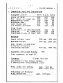
1. Operating Data and Limitations
ssaa:aa=====2•========m=•===••
Airspeed limits
Glide or dive
Max. speed in rough air
Maneuvering speed
Airplane tow
Auto winch tow
Air brakes extended
Wing flaps:
Positions L or +10 (down)
Position
+6 (down)
Positions O, -4, -7 (up)
Weights
Empty weight, appr.
Maximum weight
Max. weight of non-load
carrying structure
including payload
Approved for cloud flying
(see comments on page 16)
km/h m.p.h. knots
137
220
220
119
220
137
105
105
75
137
119
92
92
65
119
170
105
92
119
119
170
170
120
220
220
137
137
838 lbs.
380 kg,
620 kg,
1367 lbs.
400 kg,
882 lbs.
YES
Category
Glider Utility
according to the German Glider
Airworthiness Reauirements (LFS)
Weak links for towing
Frequency of flexural
wing vibration
max. 600 kg
Max. 1320 lbs.
appr. 127/min.
- 4 -
- FLIGHT MANUAL -
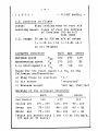
-JANUSC.G. position in flight
Win~ leading edge at root rib
Datum:
Leveling means: Slope of rear top surface
of fusela~e 100 to 4.5
tail down
C.G. range: 30 mm to 300 mm aft of datum
(+ 1.18 in.) to (+ 11.81 in.)
at all weights
Airspeed Indicator
km/h
mph
knots
Maximum speed
Maneuvering speed
l.lx stall speed 1.1
220
170
75
13?
105
46
119
92
40
Basic for the stall speed 1.1 VS1 is the
following confi~ration:
II L "
a) Wing flaps in position
"retracted"
b) Air brakes
"620 kg, 1367
c) Maximum weight
lbs·~
Marking of the Airspeed Indicator
km/h
mph
knots
i1g
Red Radial
220
13?
Yellow Arc
170- 220
105 - 137
92 - 119
Green Arc
46 - 105
40 - 92
75 - 170
46 - 105
White Arc
75 - 170
40 - 92
(white arc marked with L and +10 at 170 km/h,
105 mph or g2 knots)
- 5 J A N US -
- FLIGHT MANUAL -
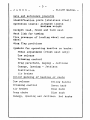
Data and Reference placards
Identification plate (stainless steel)
Operation limits: Airspeed limits
Maximum wei~ht
Cockpit load, front and back seat
Weak link for towing
Tire pressure of landing wheel and nose
wheel
Wing flap positions
Symbols for operating handles or knobs:
Pedal adjustment (front seat only)
Tow release
Trimming control
Drag parachute, Deploy - Jettison
Canopy, Opening - Jettison
Ventilation
Air brakes
Colour marking of handles or knobs
Tow release
Yellow handle
Trimming control
Green knob
Air brakes
Blue mark
Drag chute
Blue knob
Canopy, Opening and Jettison Red knobs
- 6 -JANUS-
- FLIGHT MANUAL -
2. Operating Instructions
Winch launching
Maximum tow speed:
120 km/h, 75 mph, 65 knots.
Wing flaps should be in positions o0 or+ 6°.
,-WO
The sailplane has -o-a& tow release hookson
the bottom of the fuselage(i)just in front
of the main landing wheel .{"•I) No~E~ '4.oo~
Under normal conditions winch launchings
are conducted without any difficulty.
There is no tendency to ~round loop.
With two heavy pilots the glider tends to
stand on the nose and main wheel. Then the
ground run should be started with stick
fully pulled back until the nose wheel has
ground clearance.
With the C.G. in normal positions the
take-off run should be made with stick in
neutral position.
When the glider is flown by very li~ht
pilots it is recommended to make the first
launches with stick in forward position.
Instructions for the winch driver
Especially when using a strong winch care
should be taken to avoid an excessively
sharp start, due to the acceleration which
presses the pilot back into the seat, by
which he unintentionally may pull the
stick aft.
Airplane tow
Maximum tow speed:
170 km/h, 105 mph, 92 knots.
Wing flaps should be in positions
o0 •
- 7 -JANUS-
- FLIGHT MANUAL -
There is no tendency for the ~lider to
~round loop.
With the C.G. in forward position the nose
wheel is in ~round contact. The ground run
should be started with stick fully pulled
back. Then ease the stick slowly forward
until the nose wheel has ground clearance
and the glider is running on the main wheel.
With the C.G. in normal positions take-off
should be made with stick in neutral
position.
For pilots of light wei~ht it is recommended
to begin the ground run at the first
launches with stick in forward position.
The glider pulls up very gently and does
not show any tendency to oscillate.
The take-off speed is about 70 to 90 km/h,
44 to 56 mph, 38 to 48 knots.
Due to the T-type tail plane, avoid flying
lower than the towing airplane, because
flying in its wake causes an unpleasant
beating of the control stick as a result of
wake turbulence.
Tow release
Pull the release handle fully back.
The tow release is operated by a
cable with a yellow plastic T-handle, in
the front seat at the left-hand side of the
stick and in the back seat at the left-hand
side of the instrument panel.
Adjustment of the front seat rudder pedals
The adjustment device is operated by a
Bowdencable with a plastic T-handle at the
right-hand side of the control stick.
Adjustment backward: Pull the handle and
move the pedals into the desired backward
position.
- 8 - J A N US -
- FLIGHT MANUAL -
Give the pedals a sli~ht forward push with
the heels, not with the toes, until the
locking pin en~ages self-acting with a clear
clicking noise.
Adjustment forward: Pull the handle slightly
back to unlock the mechanism and push the
pedals with the heels into the desired
forward position and lock as before.
Canopy
The one-piece plexi~lass hood is attached
by flush hin~es at the ri~ht-hand side or
the fuselage.
It is opened at the left-hand side of the
cockpit. PULL BACK the red knob of the
locking device on the canopy frame and lift
the canopy with the free hand.
Take care that the cord which holds the
opened canopy in place is attached.
The jettisoning device is mounted on the
right-hand side of the cockpit, just under
the canopy frame. For jettisoning open the
canopy as described before, then PULL BACK
the red knob at the right-hand side and
push off the canopy.
Drag parachute
The operating handle with a blue knob is
installed at the right-hand side of the
cockpit where the molded seat is attached
to the fuselage shell. It should be operated
with the right hand.
To deploy the chute push the handle forward
through the gide slot up to the center stop,
where the slot is branched off.
Moving the handle further forward up to the
front stop of the slot means jettisoning
the chute.
- 9 -
J A N U S -
- FLIGHT MANUAL -
Do not push the handle too far forward if
the drag chute should be deployed unless it
is desired to jettison the chute.
For normal landings the use of the drag
parachute is not necessary, since the air
brakes are very effective. Deploy the
parachute only in emergency.
Pack the drag parachute very carefully,
following the enclosed ''Operation and
Maintenance Instructions" of drag parachutes.
- 10 -
- FLIGHT MANUAL -
J A N U S -
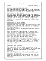
Calibration of the Airspeed indicator
Dynamic Pressure intake
Pitot tube in the nose of the fuselage.
Static pressure intake
Airspeed indicator. Cockpit frame, about
and Variometer
· 6 cm., 2 3/8" in front of
the front instr. panel.
Altimeter : Rear fuselage, about 1.2 m,
47" in front of the vertical
tail plane.
Equivalent airspeed : V (~AS)
Indicated airspeed
V' (IAS)
V(EAS) V' ( IAS) V(EAS) V' ( IAS) V(EAS) V' ( IAS)
km/h
70
80
90
100
110
120
140
160
180
200
km/h
69
80
90
100
108
117
138
158
177
198
mph
45
50
60
70
80
go
100
110
120
130
mph
44.7
50
60
68.3
78. 3
88.8
98.8
108.1
118.3
128.6
knots
38
40
50
60
70
80
go
100
110
Air density fo =- 0.125 kgs 2/m 4
knots
37.8
40
50
59.4
68.6
78.8
88.7
98.4
108.8
- 11 -
J
ANUS -
- FLIGHT MANUAL -
Flight Performances (two-seat)
W/S • 36.5 kp/m 2 , 7.48 lb/ft 2
Stall speed
70 km/h, 44 mph, 38 knots
Minimum sink
0.7 m/sec, 2.3 ft/sec
at 90 km/h, 56 mph, 49 knots
Best gliding ratio
39.5 at 110 km/h,
Max. L/D
68 mph, 59 knots
Wing flaps
The flaps have the purpose to adapt the
laminar bucket of the wing airfoil to the
respective airspeed in the best way.
Since the laminar buckets of the applied
airfoil are covering eachother widely, the
following flap positions can be accepted:
Normal flight
four positions
Landing
one position
High speed fli~ht
one position
Application
Approach and
Landin~
Flaps
L
Thermal flight +10°
Airspeed
km/h
mph
80-llo 50-68
knots
43-59
80-loo 50-62
43-54
80-loo 50-62
43-54
9o-14o
56-87
49-76
Turbulent
thermals
Best glide
+60
Flight between
thermals
High speed
_40
120-16C 75-99
65-86
-70
150-22C 93-137
81-119
00
Due to excessive stressing the airspeed
at the flap positions L and +100 (down)
must not exceed VM • 170 km/h, 105 mph or
92 knots.
- 12 -
- JANUS -
- FLIGHT MANUAL -
Longitudinal trim
The spring-type trimming device (green knob)
at the left-hand side or the cockpit,where
the seat is supported, is gradually variable.
With the C.G. in a medium position the
glider can be trimmed for steady flight at
speeds or 75 to 170 km/h, 46 to 105 mph,
40 to 92 knots.
Circling flight
The increase of stick forces when pulling
back during circling is clearly noticeable.
Opposite aileron is necessary only in turns
with greater bank, due to the selected
aileron differential.
The rudder is very effective and must be
held almost in neutral position during the
circling flight.
Full rudder and aileron is necessary to roll
from a 45° banked turn through an angle of
90 degrees.
Time taken for this motion with flaps in
position +6° is 5 seconds at a speed of
100 km/h, 62 mph, 54 knots.
Stalling characteristic
Stalls from straight flight:
Depending on the wing loading and wing flap
position, stall warning occurs at speeds of
65 to 85 km/h, 40 to 53 mph, 35 to 46 knots
by a slight oscillation of the horizontal
tail plane and the ailerons become sloppy.
By pulling the stick gently back the glider
stalls. When pulling the stick sharply back
or under gusts the glider pitches down or,
depending on the position of control surfaces
a wing may drop.
Speed is increasing very fast.
- 13 - JANUS -
- FLIGHT MANUAL -
Stalls from turnin~ fli~ht:
Pulling the stick slowly back in a turning
!light requires increasing opposite aileron
and rudder control, i.e. a~ainst the
direction of the turn.
In the fully stalled condition the ~lider
pitches down by the lower wing. It recovers
promptly from this attitude by easing the
control stick forward. Normal unstalled
flight is restored by opposite rudder and
aileron.
Behaviour at high speeds
Neglecting the influence of the high fli~ht
loads the controls are easy to be handled
at high speeds.
Excessive control movements however should
be avoided.
When flyin~ at high speeds in gusty air
care is to be taken that the safety belts
are firmly attached, due to the high
acceleration which acts upon the pilot.
Hold the control stick well fixed!
In a flight with an inclination of the
flight path of 45 degrees the air speed is
set at VNE= 220 km/h, 137 mph, 119 knots,
air brakes extended and win~ flaps in the
positiofi +6°.
Approach and Landing
The approach is normally conducted at a
speed of about 90 to 100 km/h, 56 to 62 mph,
48 to 54 knots, dependent on the wing
loading.
The air brakes are extended smoothly and
are very effective.
Sideslip is easily controlable and can be
used as landin~ aid, also with air brakes
extended.
- 14 -
- JANUS -
- FLIGHT MANUAL -
The sideslin should be initiated or
recovered with air brakes retracted to
avoid the influence of turbulence on the
horizontal tail surface.
The glider touches down on the landing wheel
and tail skid simultaneously.
The wheel brake (drum brake) works well. It
is operated by a handle on the sticks.
To avoid a long landin~ run it is advisable
to touch down at a minimum speed of 70 to
80 km/h, 43 to 50 mph, 38 to 43 knots,
dependent on the wing loading. Landing with
a speed of 95 km/h, 59 mph, 51 knots instead
means doubling the time to slow down the
energy and considerably increases the runnin
distance.
Emergencies
The sailplane can be held in a stalling
position with fully pulled stick and
necessary rudder control. Applying full
rudder in a stall brin~s the glider into a
spin.
Safe recovery from the spin is effected by
the STANDARD METHOD, which is defined as:
a) apply opposite rudder (i.e. a~ainst the
direction of the spin);
b) pause;
c) ease the control stick forward until
rotation ceases and the ~lider becomes
unstalled;
d) take the rudder into neutral position
and allow the ~lider to dive out.
The loss of hei~ht in one complete rotation
of the spin is 80 to 100 meters.
After havin~ initiated action for recovery
from the spin the ~lider speeds up very fast,
- 15 - JANUS -
- FLIGHT MANUAL -
therefore be cautious to bring the ~lider
out of the dive promptly but ~ently.
Flying in rain or with iced-up win~s means
a considerable loss of performance and
aerodynamic qualities. The minimum speed
can increase about 15 km/h, 9 mph, 8 knots.
Therefore be cautious when landing!
Come in at a speed of about 100 to 110 km/h,
62 to 68 mph, 54 to 59 knots.
Emergency exit
The roomy and well faired cockpits guarantee
a quick and safe bailing out in emergency.
Jettisoning of the canopy
1. PULL BACK the red ball knob at the
left-hand side of the canopy frame.
2. PULL BACK the red ball knob at the
right-hand side of the cockpit.
3. Throw off the canopy.
The cord which holds the opened canopy in
place is released when pullin~ back the
knob of the jettisoning device at the
right-hand side of the cockpit.
The canopy frame on the fusela~e is built
of strong fiber glass without sharp edges
and is well suited as a support for the
pilots to jump off.
- 16 -
- JANUS -
- FLIGHT MANUAL -
Cloud Flying
The sailplane has sufficient strength and
stability for cloud flying.
Nevertheless observe the following
instructions:
a) Do avoid extreme airspeeds in any case.
Make it a rule to extend the air brakes
already at speeds about 150 km/h, 93 mph,
81 knots.
b) Cloud flying is permitted only when the
following approved instruments are
installed:
(1) Airspeed Indicator
Altimeter
Turn and Bank
Variometer
5) Magnetic Compass
!~
The installation of an artificial horizon,
a clock, an accelerometer and a radio is
recommended.
c) Take care to follow the official
regulations about cloud flying.
3. Minimum Equipment
a) Airspeed Indicator 250 km/h, 160 mph,
Altimeter
14 0 knots
Four-piece safety belt
Back.cushion or parachute
b) Operating Instructions:
Flight and Service Manual
Placards indicating operation limits
- 17 - JANUS -
- FLIGHT MANUAL -
4. Wing and tail setting
Control surface movements
Angle of wing setting
2.6°
Reference: Fuselage center line
Angle or tail setting
-2.0°
Reference: Wing chord at root rib
For control surface movements see pa~e 21.
Pay attention to the tolerances if repair
work is necessary.
The travel of controls is limited by stops.
Rudder
- Adjustable stops on the back
side of the fuselage steel
tube frame.
Firm stops at the lower rudder
hinge.
Elevator
- Adjustable stops on the sticks
and their attachment bulkheads
(setscrews).
Ailerons
- Adjustable stops on the sticks,
firm stops in the wing.
Wing flaps - Locking device in the cockpit.
Air brakes - Firm stops at the operation
handles in the cockpit and on
the fusela~~ steel tube frame.
- 18 -
- FLIGHT MANUAL -
- JANUS -
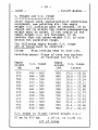
5. Weight and C.G. range
After repair work, installation of additional
equipment, new painting etc. the empty
weight C.G. position must be checked. If it
should not be within the limits,compensating
weight must be added. If the limits of the
empty weight C.G. are followed, it is
certain that the gross weight C.G. is also
within the permitted range.
The following empty wei~ht C.G. range
aft of datum must be observed.
Datum:
Wing leading edge at root rib.
Leveling means: Slope of rear top surface
of fuselage 100 to 4.5.
Empty
weight
kg
370
375
380
385
390
395
400
405
410
415
420
425
C.G. range
mm
490
484
478
472
467
461
456
448
440
-
602
598
594
591
587
583
580
576
573
432 - 569
425 - 566
418 - 563
Empty
weight
lbs.
830
840
850
860
870
880
890
goo
g10
920
930
940
C.G. range
inches
19.0
18.8
18.6
18.4
18.2
18.0
17.3
16.6
15.8
15.1
14.4
13.7
-
23.52
23.38
23.24
23.11
22.98
22.85
22.73
22.61
22.49
22.37
22.26
22.15
C.G. range in fli~ht (~ross weight C.G.)
30 mm to 300 mm;
1.18 in. to 11.81 in.
aft of datum
- 19 -
- JANUS -
- FLIGHT MANUAL -
Checking of the empty wei~ht C.G. position
To facilitate the checking of the empty
weight C.G. position by weighing the glider
at the tail skid (with fuselage in horizontal
position i.e. main landing wheel on the
ground and tail skid jacked up about 42 cm,
16.5 in. from the ground), the following
table shows the permitted maximum weight at
the tail skid for different empty weights
incl. equipment. If these tail weights,
calculated for the corresponding limits of
the extended aft empty wei~ht C.G., are not
exceeded it is certain that the empty weight
C.G. position is within the limits.
W(e) - Empty weight incl. equipment
CG(a) - Extended aft empty weight C.G.
(calculated for a min. front cockpit
load of 70 kg, 154.3 lbs.)
W(t) - Permitted maximum weight at tail skid
W(e)
CG( a)
W(t)
kg
mm
kg
602
598
594
591
587
583
580
576
573
569
566
563
30.6
30.7
30.8
31.0
31.1
31.2
31.4
31.5
31.6
31.7
31.9
32.0
370
375
380
385
390
395
400
405
410
415
420
425
W(e) CG( a)
lbs. inches
W(t)
lbs.
830
840
850
860
870
880
890
68.0
68.2
68.5
68.8
69.0
69.3
69.5
69.8
70.0
70.3
70.5
70.8
goo
910
920
930
940
23.52
23.38
23.24
23.11
22.98
22.85
22.73
22.61
22.49
22.37
22.26
22.15
- 20 -
- FLIGHT MANUAL -
- JANUS -
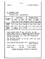
6. Cockpit load
···········•*••
(Pilots incl.
parachutes)
single-place
two-place
Cockpit
load
min.
max.
leg
lbs.
kg
front
seat
?O
154
back
seat
not
limited
min.
lbs. kg
lbs.
110
243
70
154
110
243
--
--
max.
kg lbs.
110
243
·- --
Less weight taan 70 kg, 154 lbs. in the
front seat must be compensated with ballast.
The ballast (lead or sand cushion is to be
safely attached, e.g. onto the suspension
of the seat belt.
The maximum weight or 620 kg, 1367 lbs. must
not be exceeded.
C.G. arm or the pilots incl. parachute or
back cushion
front seat :
1300 mm,
51.18 inches
back seat :
190 mm,
7.48 inches
ahead of datum (negative moments)
.59-7 (I
===--=--===:-=-==:,-?=~~=-=·~
-,-
- 21
~~==J
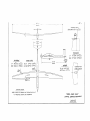
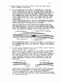
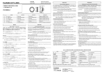
/8.20m
'
MEASURING POINT
REAR UPPER EDGE OF THE FIN
---·-------···-----,-----.--
"
~
~--·--·--·
1t::
a.gft
2.?0m
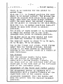
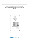
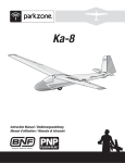
ELEVATOR
AILERONS
UP
DOWN
BO!'fJmm 3./5:-g:~in.
40~J mm
1.57~~:~ in.
WING FLAPS
MAX.lJP
2J;.±3mm o.9q.±O.IZ/n
MAK.DOWN 6(?!:'1mm 2.lf.'f±0.3/n.
201
7.'1 in
"'
f;::
UP
lf7 !'j
mm
DOWN
72 ':.'$
mq1
/.85 ~gLn
2.83 ~~·J
in.
,RUDDER
'11'0 LEFT AND RIGHT
255!:20 mm
10 to.8 in.
ON THE ELEVATOR
·~
·3mmm±SIJ
fl.8 ± 2 in.
LEVELING MEANS
SLOPE OF REAR TOP Sl.JRf:ACE OF FUSELAGE 100 TO Lf,S
i.e. FUSELAGE CENTER LINE HORIZONTAL
THREE - .SIDES V1£W"
CONTROL Sl.JRFACE MOVEMENTS
;JANUS
- 22 -
- FLIGHT MANUAL -
- JANUS -
Weight and Balance
Datum
a
...w_1_ _ _ _ b
Datum:
Wing leading edge at root rib
Leveling means: Slope or rear top surface
or fuselage 100 to 4.5
~h:__ -z~-.·- ~
Weight at landing wheel
w1
•
~3-~q:~ .....
Weight at tail skid
W2 •
• ').J·.4; ••••• •
w
=-
•••• •••• • ••
Distance
a
•
•••
Distance
b
::z
Empty weight
w1 + w2 •
)Cjj
))o5
•
• •• • • ••
5290 mm
•••••••••••
Empty weight C.G. position (aft of datum)
W2 • b
X•
W
+a•
Maximum cockpit load
•
GL
•••••• ••• ••••
D
•••••••••••
- 23 - JANUS -
- Service Manual -
R i g g i n g
The rigging of the JANUS can be done by
three persons if a support for one wing is
provided. Generally four persons will do
the rigging.
Wi n g s
Clean and lubricate the wing attachment
bolts and their bearings on the fuselage.
Put the main bolt into the cockpit within
reach.
Align the central fuselage push rods of
ailerons, wing flaps, and air brakes.
Push the air brake operating handle up to
its front stop.
Put the left wing (fork spar root) into the
cut-out of the fuselage until the wing
attachment bolts are fully inserted into
their bearings on the fuselage. Insert the
main bolt about 4 cm, 1.5 inches into the
spar bushing. Push the 8 mm dia mounting
pin through the bushing on the right-hand
side of the fuselage and the corresponding
bushing of the spar.
The wing now can be laid down on the support.
The fuselage must not be held in place any
longer.
Put in the right wing (tongue spar root)
likewise into the fuselage, wing attachment
bolts however only partly inserted into their
bearings and fork spar bolts not yet
contacting their bearings in the root rib.
Lift the right wing until the fork spar bolts
are aligned with their bearings in the root
rib. Then push the wing further into the
fuselage by moving it slightly up and down
and let the bolts slide into the bearings.
Now take out the main bolt and pull the
wings fully together by the main bolt
- 24 -
- JANUS -
- Service Manual -
bushings using the flat end of the provided
lever bar. Push the main bolt fully through
and secure its handle onto the fuselage
shell by means or a safety cowling pin.
Remove the 8mm mounting pin and put into the
cockpit pocket.
The connection of the push rods of the flaps,
ailerons, and air brakes must be made behind
the spar. The connection by the ball-spring
safety couplings requires some experience,
therefore it is advisable to get familiar
with before rigging the wings.
Connect ailerons first and flaps thereafter
taking care that the flap handle is locked
in position "L".
Each coupling should be checked after locking
by pulling across with a force of about 5 kg,
11 lbs. in the direction of releasing.
Additionally make a visual inspection!
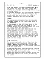
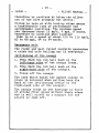
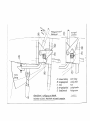
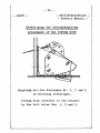
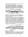
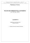
Horizontal Tail Plane (See sketch on page 26)
The horizontal tail plane should be mounted
by one person only.
Put the plane from the front onto the fin
so that the front bolt bearing fitting (A)
is just dipping into the upper opening of the
movable glass-fiber fairing on the top of the
fin.
Push the tail plane sli~htly down until its
lower surface is fully sitting on the
fairing.
Push the tail plane backwards until a clear
audible "CLICK" indicates that the locking
hooks (B) are engaged onto the axle (C).
Move the locking handle (D) using a mounting
pin of 8 mm dia in order to lock the hooks
tightly up to the rear stop.
®
}..fonfaqesftft 8mm1'
Mounti!!gp1n __ _
entriegelt
unlocked
=-=
--~-
re
(J'
Hutze
---------
---- ---- ---- ----
~
A
Vorderer 73eJChlag
8 Vernegelungshaken
C Achse
D Vern~gelunq;·hebel
E Ernstell.rchrau6e
Ho'he11Zeitwerk, Aufhangung uncl. Anfrieb
Horizontal tail plane, Attachment and control connecfton
!=ront f 1"tting
Locking hook
Axle
Lock/ng ho.ndle
selfing screw
J
A N U S
- 25 - JANUS -
- Service Manual -
When taking off the horizontal tail plane
it is advisable to do it from the rear.
Unlock the hooks (B) by pushing the locking
handle (D) forward using the 8 mm dia pin.
Push the plane simultaneously forward about
some mm (one inch) whilst knocking against
the trailing edge until the bolt is
disengaged from the bearing fitting (A).
Take otr the plane.
After rigging
Check the function or the controls.
Seal the joints of the wing and fuselage
with an adhesive tape. Seal also the access
hole for the locking handle of the horizontal
tail plane.
The sealing is very important to ensure
good flight qualities.
- 27 - JANUS C h e c k
- Service Manual L 1 s t
A) After rigging
1. Is the handle of the main bolt secured
to the fuselage by the safety cowling
pin?
2. Are the push rods of the aileronst flaps,
and air brakes safely connected by their
ball-spring couplings and checked?
3. Are the joints ot the wing and fuselage
and the hole tor the locking handle or
the horizontal tail plane sealed?
4. Does the tow release mechanism £unction
properly?
5. Does the wheel brake function properly?
6. Is the tire pressure of the main landing
wheel and nose wheel checked?
Main landing wheel: 2.75 atm., 39 psi.
N
h 1 fixed
: 1.5 atm, 21 psi.
ose w ee retractable: 2.0 atm, 28 psi.
?.
Is the horizontal tail plane safely
attached. i.e. are the locking hooks
tightly snapped onto the axle up to the
rear stop?
B) Before Take-off
1. Check the function of the control
surfaces. Do the controls reach the
limit of their travel with sufficient
ease and smoothness?
2. Do the air brakes operate properly?
Make sure to lock them after checking.
3. Is the drag chute handle locked at the
rear~stop
of the guide slot?
- 28 -
- JANUS -
- Service Manual -
4. Is the flap position in the o0 or +4°
position?
5. Is the canopy properly closed and locked?
The red knobs at the left-and right-hand
side must be in the front position.
6. Is the pilot's parachute properly
attached?
7. Are the safety belts put on and secured?
8. Is the altimeter adjusted for the
equivalent altitude or tor NN?
9. Is the radio frequency adjusted for the
airfield and/or tor the air traffic
control?
C) After take-off
Check the trim.
- 29 - JANUS -
- Service Manual -
Maintenance
Take good care ot the surface finish.
Remove all contaminations such as dust,
grass seeds, insects eto., using warm water
and a soft sponge. Use mild soap 1!
necessary. Use no polish which might attack
the paint. It is recommended to polish the
glider twice a year, using a burr and
buffing wax. By this all contamination is
removed and the surface becomes less
sensitive to new dust.
Smooth all scratches carefully with resin
filler.
Though the glider is not very affected,
protect it from moisture.
Never
a dry
after
clean
try to clean the plexiglass hood with
cloth. Use special plexiglass polish
cleaning with warm water and a sort
chamois.
Check the safety belts frequently for cuts
and stains; the metal parts for rust.
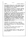
The tow release hook, mounted on the bottom
of the fuselage just in front of the main
landing wheel, is much exposed to dirt and
must be checked quite often for damages.
Keep it clean and lubricated.
It is easy to take off the tow release hook
for inspection or repair. Remove the seat,
disconnect the release cable and unscrew
the three attachment bolts.
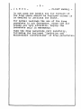
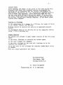
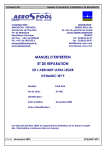
When mounting the tow release hook again
take care to attach it onto the bracket as
shown on the sketch, page 30.
- 30 - JANUS -
- Betriebshandbuoh - Service Manual -
Betest!gung der Schleppkupplung
Attachment ot the towing hook
Kupplung mit den Bohrungen Nr. 1, 3 und 5
am Beschlag befestigen.
Towing hook attached to the bracket
by the bolt holes Nos. 1, 3 and 5.
- 31 - JANUS -
- Service Manual -
The landing wheel has a drum brake which is
operated by a handle on the control sticks.
Its Bowden cable can be adjusted as usual
by a setscrew on the wheel.
The inflation pressure of the main landing
wheel should be 2.75 atm., 39 psi, that or
the nose wheel should be for the fixed
type 1.5 atm., 21 psi and for the retractable type 2.0 atm., 28 psi.
To take off the landing wheel for inspection,
cleaning, and lubrication disconnect the
Bowden cable. Remove the cotter pin and the
castle nut on one side of the wheel axle
and pull it out. Take off the wheel by
pulling it slightly back and down in order
to disengage the drum locking titting from
its guide pin on the fuselage steel tube
frame. Take care that no washers, spacers,
and bushings get lost.
Clean all parts and lubricate the bearings,
bushings and the axle.
Lubricate the bearings when a complete
overhaul is carried out, except for the
bolts and bearings of the wing attachments,
which must be cleaned and lubricated before
every rigging.
If there is any lar~er repair work to be
done, ask the manufacturer or his
representative for advice.
If a new painting should be made, take care
that the surfaces exposed to sunlight are
painted white.
- 32 -
- JANUS -
- Service Manual -
Backlash of the attachments
•••••••••••••••••••••••••••
All attachments of a glider are wearing
more or less with time. In the following
the permitted tolerances and the provisions
of repair are stated.
Wing
Tangential backlash (movement forth and
back) can occur, due to the wear of the
washers which are pressed onto the wing
attachment bolts. If the movement at the
wing tips exceeds 50 mm (1- 31/32")
additional washers of an inner diameter of
l?.95 mm and about 0.3 up to 0.5 mm thick
should be pressed onto the bolts until the
backlash is eliminated.
Ailerons and wing flaps
A backlash or up to 5 mm (3/16") measured at
the trailing ed~e of the inner aileron and
flap roots is allowable as tested in flight.
If the tolerances are exceeded ask the
manufacturer for instructions.
Horizontal tail plane (see sketch on page 26)
If tangential backlash should be observed,
i.e. if the tail plane can be moved at the
tips excessively back and forth, the setting
screws (E) must be adjusted.
Take off the tail plane. Screw out the
setting screws little by little until the
tail plane cannot be locked any longer.
Then the setting screws are to be screwed in
about a quarter turn. Tighten the lock nut
using a 5.5 mm socket wrench. When mounting
the plane thereafter the locking hooks (B)
should snap tightly onto the axle (C).
- 33 - JANUS -
- Service Manual -
It may be possible that the adjustment or
one setting screw must be different from
the other. This is the case it there is
still a backlash existing though the locking
mechanism has a very tight !it. The setting
screws then must be adjusted gradually until
both locking hooks are catching the axle
with the same tight fit.
Rudder
Due to the continuous control cables no
backlash of the rudder control occurs.
;·
:J.
11;
t
I''
ihi
i
µ
n
~~
"S
,,-:-
u
lh
1t;
: ~fo
t
,'.::"
.#·.,
• ;tjj:t
11 .;::
•fl
.,
:211.,
,;
:l';'
•• ~;· [l
. l
,; !flj
u
-ri
..
ti [i
!.'
l';
1.1
I
n~ ;::
'
·i;
1 ~ ·"
n
fl.ii
!JJ ~
!!:fjjj
[ln'-rn11m:u
. !~ i;.
.-1
~il mu:;:.ruu:='=1"'~i':"'"~10·m
:1i
" :!E
f;.{
~
l! llli
;i. lI rt
.;:tt
HU
.
t!.~: h-i
ffL't? T
. .... .
••. Ui t:.
~
~
'
tf: ; '
.
Repair Instructions for the " J A N U S "
The construction methods on the JANUS are
almost the same as used on the OPEN CIRRUS.
Therefore repairs can be performed in the
same way as described in the enclosed
instructions for the CIRRUS.
In the JANUS we find the following
construction methods:
1. Wing and Horizontal Tail Plane
Glass fiber-plastic foam sandwich,
i.e. foam CONTICELL 60, 8 mm thick
bonded on both sides with glass cloth.
2. Wing Flaps and Ailerons
Glass !iber-plaatio foam sandwich,
i.e. foam CONTICELL 60, 6 mm thick
bonded on both aides with glass cloth.
3. Rudder
Glass fiber-plastic foam sandwich,
i.e. foam CONTICELL 60, 4 mm thick
bonded on both sides with glass cloth.
4. Vertical Tail Plane (Fin)
Glass fiber-plastic foam
i.e. foam CONTICELL 60,
in the front of the spar
in the rear of the spar
5 • .Fuselage
Pure glass fiber-plastic
sandwich,
- 6 mm thick,
- 4 mm thick.
layup.
If a fracture or damage occurs to the
glider, you should first inspect the
damaged area to determine exactly the
type of construction and to find the
appropriate repair method.
Schempp-Hirth KG.
7312 Kirchheim-Teck
W.Germany
Repair Instructions
!or the Glass Fiber-Pla~tic Sailplane
"CIRRUS"
Construction
In the CIRRUS sailplane we find three basically dif !erent
construction methods. Repairs must for this reason be performed
differently on the respective pSArts.
We dif!erentiate
1. Wing and stabilizer
2. Rudder, elevator and ailerons
3. Fuselage
1.) Wings and stabilizer are built in a ribless glass fiberplastic !oam sandwich construction. This means in event of
damage that we find a PVC rigid foam (5/16 inch thick,
3.7 lb./cu.ft.) bonded on both sides with a glass cloth
laminate.
2.) The controls likewise consist of a sandwich construction.
However here the supporting core is not PVC rigid roam but
a 5/32 inch thick foamed polystyrene (Styropor) sheet with
a specific weight o! only one lb./cu.rt.
3.) The .fuselage, in contrast to the above parts, is not in sandwich construction but in a pure approximately 1/16 to 3/32 in.
thick glass fiber-plastic layup which is reinforced at two
locations with bonded-in foam rings.
The following materials apply to all parts:
Resin
Shell Epikote 162
Hardener
BASF Laromin c 260
.Mixing proportions
by weight
100 resin to 38 hardener
by volume
2 resin to 1 hardener
After proportioning stir until striations disappear.
Add filler BJfter stirring.
Glass fibers and cloth
Use only alkali-.free "E" glass cloth with Volan A or
I-550 finish (INTERGLAS).
u.s.
Weave
INTERGLAS
Style
Style
Weight
lb./sq • .ft.
91110
120
.022
92110
---
92125
---
92140
152-150
92145
uni181-150 directional
t
Crosstwill
l
Application
.058
Elevator & rudder
Fuselage, ailerons,
stabilizer
Wings & fuselage
.082
Fuselage
.044
Wings
.033
- 2 -
Rovings
GEVETEX Type ES 10-40 x 60 K 43
Foams
PVC Rigid Foam Conticell 60
5/16 in. thick, 3.7 lb./cu.ft.
Styropor THERMOPETE Super
5/32 in. thick,
1 lb./cu.ft.
Textilglas GmbH
GEVETEX
Continental AG
PORON
Kunststoff Werke
Resin - Fillers
Microballoons, white
Union Carbide
Microballoons, brown
(Brenntag GmbH)
Aerosil
Degussa-Wolf gang
Styropor kernels 1/16 - 3/32 dia.
BASF
(expanded polystyrene kernels)
Chopped cotton wool
Lacquer
PE - Lackvorgelatt white
Lesonal-Werke
No. 3-6910
(resin paint)
PE - Hardener
No. 7-2050 or 7-2051 (100 "kJ l.S)
Mixing proportions by weight
100 parts Lackvorgelat to 10 parts hardener
PE - Thinner
No. 6-3026
No. 62 507 2-6q15
PE - Hardener
No. 7-2050 or 7-2051{!OOto1.5)
Mixing proportions by weight
100 parts filler to 10 parts hardener
Resin paint "La.ckvorgelat" and filler can be mixed in
one-to-one or other proportions.
PE - Filler, white
Repair
Should a fracture or damage occur to the sailplane, you should
first inspect the damaged area to determine exactly the extent
of dam.age and type of construction. The type and density of
weave can usually be determined by sanding to the cloth.
If this is not possible, break off a piece of the laminate
and ignite it. After the resin is burned the type, density and
direction of the weave will be evident.
I. Damage to Wing or Stabilizer
The dam.ages which can be repaired by you fall into two
groups.
a) Simple surface damage (only the outer glass fiber
laminate damaged)
- 3 b) Destruction of the whole shell (also the inner glass
fiber laminate destroyed)
a.) I! the outer shell receives a puncture or a fracture,
tap to determine the extent of delamination from the
foam.. Follow by removing the lacquer with a sanding diac
or block and remove from the foam the portion or the
shell which has become delaminated. Around the edge or
the dam.aged area where the shell is still firmly bonded,
scarf with an abrasive block or a plane blade at least
1-1/2 inches (for each cloth layer about 3/4 inch is
necessary).
After scarfing the shell, blow out thoroughly the whole
repair area including the pores of the foam and wash the
scarf with carbon tetrachloride or acetone.
Now fill the hole in the foam. with microballoons and
simultaneously !ill the pores of the exposed foam. Then
lay three ~atches of the 92110 cloth with diagonal weave
direction lstepwise largest patch first) over the damaged
area.. The applied cloth must be dry and dust free.
c
3 latYers 92110 diagonal
Outer laminate
0
t>
o o o ·o
& O
O
o
t>
o
o o
•o o o o o o
Oo
oo
-
C>OOOa
0
0
0
0
0
0
Micro balloons
Conticell 60
After hardening (appr. 8 hrs. at 20 deg. C. or 68 deg. F.)
the damaged area should be smoothed, filled and painted.
In smoothing take care that only the edges of the patches
are sanded.
Inner laminate
b.) If there is a through hole in the sandwich shell then the
inner laminate must be repaired.
We remove the outer laminate in the region of the damage
which is no longer bonded to the foam and enlarge the
hole in the foam and inner laminate until good bonding to
the foam is evidenced. Then the foam is further removed
3/4 inch around the hole in the inner laminate and the
outer laminate scarfed as under paragraph a. Now the
projecting inner laminate is cleaned of any f oa.m and
!eathered.
l~q--
l~q
ot7ouoooo
C>O
0
0
00
o
0
0
00
o
0
00
0
0
0
•o
0
0
3/4"'
I! the hole in the foam is smaller than a fist then glue
with Patex a thin plywood or polyester plate from the
inside to the laminate, lay on the inner laminate
( 1 layer 92125 ~ or 2 layers 92110 ~ ) and fill the hole
in the foam with microballoons mixed with Styropor kernels
or crumbled Styropor.
- 4 -
If you are not hurried let it harden (8 hrs. at 68 deg. F.)
sand and apply the outer patches.
A tip on gluing the plywood plate - the hole in the
inner laminate should always be a bit oblong so as to
insert the plywood backing plate. Be!ore inserting the
plywood drive through the middle of the ply a pin or
nail by which it can be drawn against the inner shell.
With additional nails or pine it is in this manner
possible to close very large holes to the proper contour
to lay the cloth patch on.
[Outer laminate
Microb. with
Styropor kernels
ooo
0
-Pin
ooo
I
¥z
II
Scarf'
0
0
0
0
0
0
C>
0
6
Inner laminate
Thin plywood backing
Basically it is possible to repair also larger shell
parts in the foregoing manner. Because of weight you
should use a plug of foam in place of the microballoons
and Styropor kernels.
In these cases proceed as fallows: You cut or sand a
plug of foam (Conticell 60) to fit the hole, spread the
inner side thinly with microbaJ.loons (to close the pores)
and lay on it the inner laminate. The inner laminate must
harden before doing further work. If the hardening is
complete or at least progressed so that the laminate does
not separate from the foam. then glue the plug in the
hole with thickened resin ~chopped cotton wool, microballoons). The foam with laminate on one side is flexible
so that it can be fitted to the wing contour (if necessary
warm the foam with a hairdryer and bend). Once the foam
is glued it can be smoothed, puttied with microballoons
and the outer laminate applied.
Caution: Avoid strong heat, otherwise air bubbles form.
r
Outer laminate
I
Puttied microb. surfac:=
0
0
.
c
0
o
0
11
0
0
0
Replacement piece
Conticell 60
II. Damage to the Controls
Basically the same procedure can be used as on the wing.
Only in place of the PVC foam a polystyrene foam layer,
"Styropor Thermopete Super" 5/32 inch thick, is used.
The Styropor piece need not be coated with microballoons,
the cloth adheres very well with pure or slightly
- 5 thickened resin which must not harden in any case before
doing further work. However with larger replacement
pieces you should let the laminate harden on one side
and glue the foam thereto in order to keep the surface
wave free.
Caution: Do not apply too much heat to freshly laid cloth
otherwise it causes ugly blisters and you must
a.tart over.
Caution: On the controls minimize weight in the repair.
The surface should require very little filling.
III. Damage to the Fuselage
In the repair of the fuselage we save the annoying
replacement of the foam. We have here, as already mentioned,
only to do with the simple glass laminate which in most
places consists of ~Slayers. Therefore we need larger
scarfs. These should, for larger holes or cuts, never be
less than3-1/8 inches wide. With all fuselage shell
repairs apply resin first to a layer of 92110
cloth
following with ~Slayers of 92140 cloth alternating the
weave lengthwise and diagonally. Then you are always on
the safe side. Each succeeding layer should be about
3/8 to 1/2 inch smaller than that under it.
+
1 layer 92110
E+
5
layers 92140
'S((
'$(<" =IF
+
For small holes or fractures the repair is no problem.
You sand your scarf, clean well with carbon tetrachloride
or acetone, lay on the cloth layers and, if the resin is
dry, can finish the whole repair with microballoons after
2 or 3 hours.
Caution: If the room is cold or if you are hurried you
should nonetheless not use a concentrated hot air stream.
Better, make a large tent over the area from aluminum
foil and heat the space from a safe distance. There is
little likelihood of blisters but overheating can occur
and the resin may become brown. If you do not have a
source of hot air, put a sheet of foil over the applied
cloth and use a heat pad or hot water bottle.
For larger holes in the tailcone not accessible from the
inside, we must again fabricate a backing on which to
contour the repair cloth. This can be retained as discussed previously with the aid of plywood, a nail and a
little Patex. It cannot later fall out, the cloth being
directly on the plywood and so is bonded thereto. After
the plywood backing is secured proceed as previously
discussed.
- 6 -
Lacquer Work
After sanding the edges of the patch or the area filled with
microballoons until the original contour is attained the
puttying can be abandoned and the lacquer (PE-Vorgelat or
PE-Vorgelat and filler in 1 to 1 proportion) applied directly
with a brush (not sprayed). After hardening sand the area
and wet sand with 360 grit wet-or-dry paper. If at no place
the weave shows then final sanding can be done with 600 grit
wet-or-dry. Polish with rubbing compound. If the weave shows
repaint with lacquer.
Repairs to Fittings
At the appearance of a damage to a fitting, the cause of which
is not known, contact the factory.
Welding should be carried out only by an approved aircraft
welder.
All weldments made by the factory are by the Argon-arc method
using 1.7324.0 welding rod.
Larger Repairs
You should not attempt to make larger repairs of the following
types:
If the wing, fuselage or controls are broken apart.
If the spar flanges are damaged.
If the main fittings at the root rib, fuselage or in the
controls are broken out.
If in the area of the fittings the laminate shows white areas
or cracks.
When you cannot guarantee the repair.
Kirchheim-Teck
26th March 1968
Schempp-Hirth K.G.
ss
Translation by
Klaus Holighaus
F. H. Matteson
Service and Maintenance Instructions
for the
Brake Parachutes on Sailplanes
Model
Model
Model
• • • • •
•••••
• • • • •
BS 1000
BS 1300
BS 1600
Date: November 1968
Manufacturer:
Walter Kostelezki KG
7987 Weingarten I Wuertt.
W. Germany
- 1 -
1
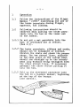
Operation
1.1
Follow the instructions of the Flight
Manual " JANUS" concerning the use of
the brake parachute during flight,
approach, and landing.
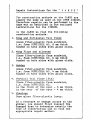
1.2
Following instructions should be
observed when putting the brake parachute into its box on the lower end
of the rudder.
1.2.1 Do not put a wet parachute into the
box. If necessary dry it before.
(See 2.5).
1.2.2 The brake parachute, ribbons and cords,
should not be entangled or twisted.
Stretch the chute and check its proper
shape. The two shroud lines, adjacent
to the name plate on the canopy base,
should run straight up to the attachment loop without being entangled with
the other shroud lines. If necessary
untangle the chute before putting it
into the box.
1.2.3 Fold up the stretched parachute into
the box in a S-shape manner, beginning
at the top of the canopy.
(See sketch).
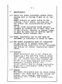
- 2 2
.Maintenance
2.1 Check the brake parachute always after
having used it during !light or at landing.
Minor defects as small holes in the
ribbons, little wears, soiling etc. do
not affect the serviceability of the
chute.
!£ the brake parachute shows greater
damages as tearing off of more than 10%
of the ribbons, spacers or shroud lines,
it must be taken out of service and be
repaired before further use.
2.2 Brake parachutes not in use must be
reviewed in intervals of about 60 days.
2.3 The brake parachutes must be inspected
at the end of 12 months after the
manufacturing inspection of the sailplane
and during the annual inspections thereafter.
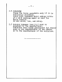
2.4 Storage
Brake parachutes not in use should be
stored in a dry and airy room at about
20°c (68°F) and 65% rel. humiditiy of
the air. Protect them from vermins and
do not store them together with food 1
chemicals (battery acids) etc.
Do not expose them to strong insolation
which has a detrimental effect on the
ribbon fabric.
2.5 Drying
Wet brake parachutes must be dried before
further use. Hang them up for airing and
drying. Avoid however temperatures
exceeding 40°C (104°F) and strong insolation.
- 3 2.6 Cleaning
Clean the brake parachute only if it is
absolutely necessary.
Clean with lukewarm water adding little
of a mild washing agent as used for
Nylon fabrics.
Do not scrub, rub, and wring.
2.? Greater damages (see 2.1) must be
repaired by the manufacturer.
There!ore send brake parachutes for repair
only to the manufacture.r of the chutes
or to the manufacturer or the sailplane.
--- _________________ __
....,..