1
ReDSeeDS User Guide
(for version 0.6.2)
v. 0.01
Lucyna Skrzypek, Piotr Łabęcki
Translation and edition:
edition: Michał Śmiałek
Warsaw University
of Technology
smog.iem.pw.edu.pl
Table of Contents
TABLE OF CONTENTS ........................................................................................................................................ 1
1
INTRODUCTION ....................................................................................................................................... 2
2
WORKING WITH REDSEEDS ..................................................................................................................... 5
3
2.1
RUNNING THE TOOL AND MANAGING PROJECTS ................................................................................................... 5
2.2
CREATING USE CASES ...................................................................................................................................... 6
2.3
CREATING SCENARIOS AND VOCABULARY NOTIONS ............................................................................................... 7
2.4
NOTION MANAGEMENT ................................................................................................................................ 10
2.5
VALIDATION AND CODE GENERATION ............................................................................................................... 13
WORKING WITH THE GENERATED CODE ............................................................................................... 14
3.1
OVERVIEW OF THE GENERATED CODE ............................................................................................................... 14
3.2
DATA TRANSFER AND DATA ACCESS OBJECTS .................................................................................................... 15
3.3
THE VIEW LAYER .......................................................................................................................................... 18
3.4
THE PRESENTER LAYER .................................................................................................................................. 24
3.5
THE MODEL LAYER ....................................................................................................................................... 26
1
1 Introduction
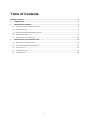
The main characteristic of ReDSeeDS is the construction of software, driven by requirements models.
This changes proportions in which the analysts and programmers participate in software development
– reducing the need for direct programming in e.g. Java. ReDSeeDS uses familiar notation of use cases, scenarios and domain models (vocabulary). Assuming correct structure of the requirements model
it becomes possible to generate automatically a significant amount of application code. This results in
reducing the role of programmers to updating the code generated by ReDSeeDS.
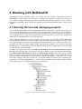
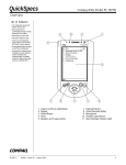
Figure 1: Main ReDSeeDS screen
Requirements are specified within ReDSeeDS in a comprehensible yet formally precise language
called RSL (Requirements Specification Language). ReDSeeDS contains a sophisticated editor of
RSL. The fundamental structure of the language can be summarized by the following informal formula:
RSL = actors + use cases +scenarios + notion vocabulary
RSL is the first language that coherently embeds vocabulary and domain (notion) modeling into use
case modeling. This way it assures much better coherence and comprehensibility of specifications.
RSL allows for defining relations between domain elements and their visualization in diagrams. It also
determines ways to denote various phrases and notions to be able to generate good quality architectures of the target applications. The basis for this are simple Subject-Verb-Object sentences that define
the application logic. RSL has several common points with UML but it defines its own specific constructs and concentrates on requirements modelling.
RSL is defined using a so-called metamodel. Metamodels are models that describe other models at an
abstract level. In practice, such models are represented as a set of related metaclasses with textual de2
scriptions. Appropriate definition of relations between metaclasses allows for defining the grammar of
a given modelling language.
Models and metamodels form a 4-level framework:
•
•
•
•
M0 – model instances (concrete objects of model elements like classes or use cases),
M1 – models (e.g. UML class models or use case models),
M2 – metamodels (metaclasses that represent language elements, e.g. classes and use cases),
M3 – metametamodels (metaclasses that represent elements of the language at level M2).
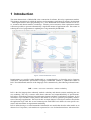
An example of a metamodel at level M2 (left), a model at level M1 (right) and concrete syntax at level
M0 (bottom) are presented in Figure 2.
Figure 2: RSL metamodel fragment
An important feature of the ReDSeeDS system is that is can generate Java code from RSL models.
This code complies with the Model-View-Presenter architectural pattern. Based on the requirements
models, ReDSeeDS creates the majority of the application logic (Presenter) and the user interface
(View), compliant with the Echo3 web technology. It also generates DAOs (Data Access Objects) and
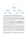
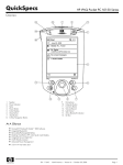
DTOs (Data Transfer Objects). Figure 3 presents the general schema of this transformation with an
example RSL specification transformed into code. Many details are presented further in this guide.
3
Figure 3: Example translation into code
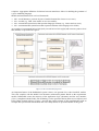
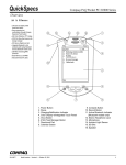
To generate code, ReDSeeDS uses standard code generators of UML tools: Enterprise Architect [x] or
Modelio [y]. After performing a transformation from RSL to UML, the UML models are transferred to
one of the UML tools and then their code generator executed. The transformation is written in a special model transformation language MOLA [z], according to the rules that are discussed further in this
guide. This process is presented in Figure 4.
Figure 4: Schema of the transaltion process
4
2 Working with ReDSeeDS
This chapter presents important aspects of working with the software requirements using the
ReDSeeDS tool. We will present such issues as: creating a new project, conventions for writing use
case scenarios, adding and managing notions, validation of models and generation of code. All these
elements are illustrated with an example specification for a Public Sport and Recreation Centre system
(PSRC).
2.1 Running the tool and managing projects
We can run the ReDSeeDS tool by selecting the batch file “redseeds.bat”. This file first runs the socalled JWGNL terminology server and then – the actual application (“redseeds.exe”). The terminology server can be minimized but it has to be running at all times. The server is responsible for terminology management that is used within requirements specifications. This is used for the requirements
reuse features of ReDSeeDS, not covered by this guide.
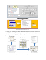
After running the application, we need to select a new workspace. It is a folder to which ReDSeeDS
will save the specifications we create. In order to copy our work to another computer we need to copy
this whole workspace folder. For easier handling, it is recommended to use a compression (ZIP) facility to place the folder in a single compressed file. Apart from the workspace, we also need to move the
terminology file “wordnetgraph.tg”from the JWGNL folder. This file contains all the new terms that
we have added in our requirements.
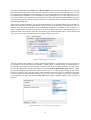
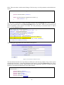
To create a new project we need to select File New Project, then select New Software Case Project and enter the project name. This creates a new project where we can create requirements packages
using Requirement Specification New Requirements Package in the tree browser context
menu. To structure our model we can create many requirements packages. In our example project we
divide the functional requirements specification into logical sub-packages. At the first level – by the
user (client, manager) and at the second level – by the functionality area (fitness club, swimming pool,
promotions, reservation management etc.). Such a division introduces order which facilitates further
work with the project. The effect of this can be seen in Figure 5.
Figure 5: Division of requirements into packages
5
2.2 Creating use cases
After creating packages, we can add requirements – use cases. To add a use case, we can first create a
use case diagram using New Use Case Diagram in the tree browser context menu. This creates a
new blank page where we can arrange use cases and associated actors. To add one of these elements
we can drag them from the Palette tool bar or use a context menu option (Add Use Case or Add
Actor). Adding a new use case in a diagram places it also in the current package in the tree browser. Adding an actor automatically places it in the Domain Specification Actors package.
After placing actors and use cases on a diagram we can relate them through dragging relationship
lines. This is possible only for actor – use case relationships. To relate two use cases we need to modify one of the use case’s scenarios. We should add an «invoke» sentence and choose the invoked use
case from a drop-down list (more about this later in this chapter). This will automatically create a directed relationship between that use case and the invoked one. The relationship is depicted by a dashed
arrow. It should be emphasized that RSL does not contain the standard «extend» and «include» relationships known from UML. Instead, it introduces the new «invoke» relationship which is much more
semantically precise.
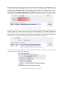
Figures 6 and 7 present two example use case diagrams for the PSRC system. More diagrams and the
full model can be downloaded from www.redseeds.eu (tutorials section).
Figure 6: Using the fitness club by the client
6
Figure 7: Managing the fitness club
2.3 Creating scenarios and vocabulary notions
After defining use cases we can proceed to writing their scenarios. For this purpose we need to select
(double-click) a use case and go to the scenario tab in the use case details window. In order to start
writing a scenario we first need to click at the Create SVO Sentence button, which will add the first
sentence. After this we can write consecutive sentences which will have numbers assigned, after pressing Enter or clicking the create sentence icons. Above the first sentence, we can find the Precondition
section where we can introduce the conditions under which the use case can be started. The preconditions have no specific syntax and can be entered as free text.
The main scenario sentences have to follow a specific syntax with additional conventions. The basic
syntax is Subject – Verb – Object (noun verb noun), for example: “System saves book”. Normally,
articles (“a”, “the”) are not used. It is also possible to add a second (indirect) object with a preposition
but this is not recommended due to that it is not supported by code generation facilities. A general rule
is to build the simplest and shortest possible sentences. This prevents from generating redundant application logic code. It has to be also noted that the words used in sentences are reflected in code, so it
is not advised to use non-latin (country-specific) characters.
For every use case, many alternative scenarios can be created. To do this, we need to select the Fork
scenario button when writing any of the scenarios. This will effect in adding a condition sentence in
the current scenario and another condition in a newly created alternative scenario. The new scenario
will be available in an additional tab. I should be noted that the newly created scenario shows all the
sentences from the main scenario that are prior to the fork. For instance, if the main scenario has 4
sentences, after which a fork was made (adding a condition sentence), also the alternative scenario will
show the same 4 sentences but with a different condition sentence that follows them. After the alternative condition, we can enter the alternative scenario sentences. They will be numbered according to the
number of the last sentence before the fork (e.g. 4.1.1, 4.1.2). After the alternative scenario is finished,
it can return to the main scenario. This can be done by selecting Create rejoin sentence. After creating sucha a sentence, we need to select a specific sentence in another scenario to which the rejoining is
to be made.
When the scenario finishes use case execution we should specify the final status for that scenario.
There are two possible options to choose: Create final/success sentence (for positive endings) and
Create final/failure sentence (for negative – e.g. erroneous – endings). This creates the final status
7
statement of either success or failure and a Postcondition section. In the postcondition we can specify
the desired state of the system at the end of the specific scenario. It can be noticed that a use case can
have only one precondition (at the beginning) and several postconditions (for each alternative scenario). Entering these conditions is not necessary for code generation but it is worth doing for two reasons. Fists, it makes the requirements specification more clear and facilitates understanding. Second, it
can clarify the generated code because the conditions are transformed into comments at relevant places
within the generated code.
After writing scenario sentences, we need to mark their parts. It is recommended to first write the scenario text if full and only then mark sentence parts. This helps in detecting possible logical errors in
scenario flow and does not distract from determining meritorious correctness of the scenarios. To
mark a sentence part, we need to select the given word or phrase and choose the appropriate part of
speech from the context menu. After this, the sentence part is denoted with colour – nouns in blue and
verbs in red. An example for sentence part marking is shown in Figure 8.
Figure 8: Marking sentence parts
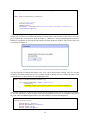
After the sentences are marked, we need to add notions and their so-called senses. This process has to
be performed to build the domain specification. Adding senses is needed mostly for requirements reuse and we will not discuss it in this guide. To add a notion from a scenario sentence, we need to double-click the appropriate sentence part. This will open the Domain Statement Editor window. In this
window, the appropriate sentence part is shown. If we click it, we will be able to define its sense. This
is shown in Figure 10. We can select one of the available senses from a list. For common words, their
senses are taken from the WordNet database. If none of the senses is suitable, or no sense is available,
we can add our own sense by selecting Add sense which opens a separate window. This is shown in
Figure 9.
Figure 9: Adding a nes sense for a word/phrase
8
In the domain editor, the phrases that are not yet turned into domain notions, are highlighted in red. If
we don’t want to play with adding senses by hand, we can use an automatic option. This is available
through pressing the Add all button. This automatically adds all the senses (generates new ones or
selects the first ones from the lists) and inserts notions and verb phrases to the domain model. We can
then find them under Domain Specification Notions in the project tree browser. Figure 10 illustrates a typical domain editor window during the process of adding a new notion to the domain model.
Figure 10: Assigning a sense to a notion
According to the Subject – Verb – Object syntax, the first part of each sentence is automatically detected as an actor or a system element. Thus, when we select the first part of a sentence, instead of the
domain statement editor we will see another window. This window offers just a single selection between an actor and a system element. As for the domain elements, the actor or the system element can
have their sense assigned automatically by the system. This is illustrated in Figure 11.
Figure 11: Selecting actors and system elements
As a summary of the above guidelines we can study Figures 12 and 13 which show two well-formed
scenarios, ready for potential code generation.
Figure 12: Example main use case scenario
9
Figure 13: Example alternative scenario
2.4 Notion management
After the notions were created from use case scenarios, they need to be organized. We need to specify
which notions denote elements of the user interface (widows, messages, forms, etc.), which denote
elements of the business domain, and which are their attributes. To make the distinction clear, we
should preferably place each of the notion types in separate packages. This can be done by selecting
New Notions Package in the project browser context menu.
The package containing user interface elements can be named with a name starting with “!UI” (e.g.
“!UIElements”). Elements in this package will be various windows and buttons for which specific UI
classes will be generated in code. It is recommended to place all the buttons in a sub-package of
!UIElements, called “!Buttons”.
All the business domain elements can be placed under the package called simply “Notions”. A separate package is recommended for notion attributes, called “!Attributes”. It is a characteristic feature of
RSL, that the attributes are kept as separate entities in the model. A single attribute (e.g. “name”) can
be assigned to different domain notions (e.g. the “name” of a “person” and the “name” of a “club facility”).
To add an attribute to a domain notion, we need to make two operations. First, we need to mark an
element as an attribute (and preferably place it under “!Attributes”). This is done by selecting “Attribute” as the element type in the domain element editor. In addition to this, we need to add a special
marker <at> in the Description field. This is needed for older versions of the ReDSeeDS code generator and will not be needed in the future. The effect of this marking is illustrated in Figure 14.
Figure 14: Attribute marking
The second operation is to drag the attribute and add it to another domain element. This should be
done in the project browser field. We need to drop an attribute at the domain element. Then, we need
to select Add as attribute, and the dropped attribute will be shown on the attribute list of the domain
elements. An example of this is shown in Figure 15.
10
Figure 15: Attrributes assigned to the “credential” notion
RSL provides the capability to add our own markers to domain elements. For the current code generator, several markers are predefined. The marker should be selected from the drop-down list and/or
(depending on the generator version) entered in the Description field. The following table summarizes
the predefined markers.
Notion type
Marking
Remarks
Domain notion
None
Domain notions can be related with other domain notions, attributes, lists and screens.
List
<li>
A List has to be related to just single Domain notion –
the list element type. Multiplicity at the list element side
has to be set to „*’’. A list can be related to a screen.
Attribute
<at>
An Attribute has to have a primitive type assigned
(String, Integer, Boolean, Date, etc.). An Attribute can
be related with any number of Domain notions.
Screen (Frame)
<fr>
A Screen can be related with any number of Domain
notions or Lists.
11
Button (Trigger)
Message
<tr>
Buttons can be (optionally) related to Screens.
<ms>
Contents
</ms>
Figure 16 presents an example of mapping between the above notion types and elements of the user
interface.
Figure 16: Example mappings between notions and UI elements
While tidying up the notions in the Notions package, the user can create a notions diagram. This diagram can help in presenting clearly the relationships existing in the domain vocabulary. For this purpose, we need to select the option New Notions Diagram. Then, we can drag all the necessary
notions from the project browser tree. We can also create new notions by selecting them from the
toolbar. We need to remember not to place too many notions on one diagram because it reduces its
comprehensibility. An example notions diagram, presenting notions related to the “Create profile” use
case is presented in Figure 17.
12
Figure 17: Diagram pojęć dla przypadku użycia „Create profile”
2.5 Validation and code generation
Before we start generating Java code, it is a good idea to validate the requirements specification. For
this purpose we should open the context menu for the Requirements Specification package and
choose the Validate option. This will invoke a validation procedure which will detect errors and issue
warnings. When there are no errors, we can try generating code. To do this, we again need to select the
context menu for the Requirements Specification package and then choose the Generate Implementation option. This starts the transformation process. The transformation exports the generated models
and code to either Enterprise Architect or Modelio. Selection of the tool and some parameters of the
target code (like folders) can be set in the configuration window (Window Preferences ReDSeeDS/Generation).
The transformation process can take some minutes and it finishes with an appropriate message. This
creates new elements in the project browser tree, under Architecture or Detailed Design. In case for
generation using Enterprise Architect, also the Code folder will be created and an appropriate EAP file
will appear, which is illustrated in Figure 18. For generation to Modelio, the generation will update the
workspace according to the parameters (folders) set in the configuration window.
Figure 18: Structure of the generated implementation
13
3 Working with the generated code
This chapter presents a detailed description of how to implement a system, based on our PSRC system
example. We will use the code generated by ReDSeeDS and update it to obtain a fully working system. We will present which code was automatically generated and which needs modification.
3.1 Overview of the generated code
The generated code is placed in the “App” folder in the target workspace. It contains classes and interfaces grouped into appropriate packages. The structure of this Java code follows the Model-ViewPresenter (MVP) pattern. MVP is a popular architectural pattern used to separate the application logic
from presentation and domain logic. This way, the UI code is clearly distinguished from the data processing code and the code that controls the application. This results in better clarity of code and easier
maintenance. MVP application can be also subject to relatively easy shifts in the applied technology.
Figure 19: Graphical presentation of the MVP parttern
Each of the three MVP layers is responsible for specific tasks, illustrated in Figure 19. The View layer
is responsible for displaying data that is passed by the Presenter layer from the Model layer. The View
also handles passing data from the user, down to the Presenter. This is normally done using event handlers. The main role of the Presenter is to control the sequence of updates made to the Model and to
the View. The Presenter can request data from the Model and then pass it to the View, and vice-versa.
It is thus an intermediary between these two layers. What is important, the View and the Model do not
communicate directly and have no knowledge of themselves. The Model layer is responsible for executing the domain logic. It processes data and persists it (usually using a database).
The “App” folder has to be placed within the workspace of a programming IDE. For instance, in
Eclipse, we need to create a new project and import code into it. If the transformation in ReDSeeDS is
configured correctly, code can be placed under the appropriate project automatically. Figure 20 presents the code structure for the PSRC system, imported into Eclipse.
14
Figure 20: Example of the generated package structure
Appropriately named packages realize the above described layers of the MVP pattern. It can be also
noted that besides the three layers, the transformation generates Data Transfer Objects (DTO) and
Data Access Objects (DAO) which will be explained in the next sections.
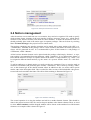
3.2 Data Transfer and Data Access Objects
We will start by explaining the supportive packages of „App.DTO”, „App.DAO” and
„App.DAO.util”. As it was already mentioned, data flows between the three layers. To handle this
data, we can group it into special classes that are called Data Transfer Objects. ReDSeeDS generated
DTOs from the domain notions (not UI elements). All the DTO classes have the “X” prefix added and
placed in the „App.DTO” package. Figure 21 presents some example contents for our example system.
Figure 21: Example contents of “App.DTO”
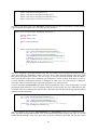
When the domain notions have appropriately assigned attributes, the DTO classes will have these attributes generated, together with a default constructor and “get” and “set” operations.
public class XTrainerData {
private
private
private
private
private
private
String description;
String email;
String specialization;
String trainerFullName;
int xTrainerDataID;
int yearsOfExperience;
15
public XTrainerData(){
}
...
public String getDescription(){
return description;
}
...
public void setDescription(String description){
this.description = description;
}
}
The above code fragment shows part of the DTO structure generated for the Trainer Data notion. The
first part contains declarations of all the attributes and the standard constructor. This is followed by the
getters and setters, here presented only for the “description” attribute. Similar methods are generated
for other attributes. This illustrates the advantage of assigning all the attributes in the requirements
model. In such situation, the code is ready to be used and needs no manual changes.
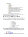
Further helpful elements generated by ReDSeeDS are the Data Access Objects. They provide an interface for communication with the data source, which in this case is the H2 database. They separate the
domain logic from the data access part. All the DAOs are generated from the same domain notions as
the DTOs. Their name has the “DAO” suffix added and they are placed in the “App.DAO” package.
Example contents of this package is presented in Figure 22.
Figure 22: Example contents of “App.DAO”
All the classes shown in Figure 22 implement the IObjectDAO interface. This interface contains declarations of key operations for managing the data in the database. These operations allow for writing,
reading, modifying and deleting database elements. For this code to work correctly, some manual
changes are needed. This is illustrated in the following code fragment which presents the method that
writes a new Promotion object to the database.
public int savePromotion(XPromotionData p) {
int res = 0;
Statement stm = null;
try {
stm = this.connection.createStatement();
int id = getRowCount("PROMOTION");
String sql = "INSERT INTO PUBLIC.PROMOTION "
+"(ID, NAME, DESCRIPTION, DISCOUNT, EXPIRATION_DATE, TYPE)"
+" VALUES ("+ id +", '"+ p.getPromotionName() +"','"
+ p.getDescription() +"',"+ p.getDiscount() +" ,'"
+ p.getExpirationDate() +"','"+ p.getType() +"');";
16
res = stm.executeUpdate(sql);
} catch (SQLException e) {
e.printStackTrace();
} finally {
if (stm != null) {
try {
stm.close();
} catch (SQLException e) {
e.printStackTrace();
}
}
}
return res;
}
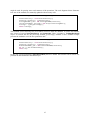
The DAO code has to be aligned with the database structure which is currently not generated by
ReDSeeDS. For the above code, the structure is illustrated in Figure 23. The database has to be designed and implemented in an external tool.
Figure 23: Example database table
DAO classes are supported by the code generated in the “App.DAO.utils” package. An important class
which is part of this package is ConnectionFactory, and its fragment is shown below.
public class ConnectionFactory {
private String dbDriver = "org.h2.Driver";
private static ConnectionFactory factory = null;
private String password = "";
private Properties prop = new Properties();
private
String
url
=
"jdbc:h2:file:C:\\Studia\\Sem
dyplomowa\\Baza\\mosir.db";
private String user = "sa";
(...)
public ConnectionFactory(){
try {
Class.forName(dbDriver);
prop.setProperty("user", user);
prop.put("password", password);
} catch (ClassNotFoundException e) {
e.printStackTrace();
}
}
(...)
public Connection getConnection(){
Connection conn = null;
try {
conn = DriverManager.getConnection(url, prop);
} catch (SQLException e) {
e.printStackTrace();
}
17
7\\Praca
return conn;
}
}
The important parameter is “dbDriver”, which points to the name of the database controlled for the H2
database. The “url” parameter refers to the path where the database file resides. By default, this address is seen as the user’s home catalogue with its name beginning with “test”. The getConnection()
method is responsible for establishing connection with the indicated URL.
3.3 The View layer
The “App.View” package contains all the code responsible for interaction of the user with the application. The current ReDSeeDS transformation generates classes that conform to the Echo 3 web UI
technology. All the View classes have the “V” prefix. They are created from the respectively typed
notions from the domain model written in RSL. Typically, it involves the notions placed previously in
the “UI” packages like !UIPages, !UIForms or !UIMessages. The generator creates various components of the user interface code like web pages, forms, message windows. Thus, the “App.View”
package is vast. Its main interface is called IView. The main classes are EchoApp and EchoServlet.
IView contains declarations of operations that are responsible for displaying respective UI elements.
The EchoApp class implements the IView interface. Its implementation is generated in its entirety by
ReDSeeDS and does not necessitate any manual changes. The following fragment presents the code
for the method that displays the application’s main page. The methods that display other UI elementa
have similar structure.
public void showCustomerApplicationPage(){
if (currentPage != null)
pageStack.push(currentPage);
VCustomerApplicationPage page = new VCustomerApplicationPage();
page.init(presenter);
show(page);
}
Pages are responsible mainly for presenting data to the users. They also enable navigation through
various buttons and associated event handlers. For example the VHomePage class represents the application’s start page. From this point, the user can decide to navigate to one of the client or manager
subpages by pressing a button. The following fragment presents an example of code for rendering
buttons and defining the associated event handlers.
public class VHomePage extends ContentPane implements ActionListener {
private
private
private
private
private
MutableStyle buttonStyle;
Column column;
IPresenter presenter;
Button customerApplicationButton;
Button managerApplicationButton;
...
public void actionPerformed(ActionEvent e){
if (e.getActionCommand().equals("customerApplicationButton")) {
presenter.SelectsCustomerApplicationButton();
}
if (e.getActionCommand().equals("managerApplicationButton")) {
presenter.SelectsManagerApplicationButton();
}
}
...
private void addContent(){
customerApplicationButton = new Button("Customer application");
18
customerApplicationButton.setStyle(buttonStyle);
customerApplicationButton.setActionCommand("customerApplicationButton”);
customerApplicationButton.addActionListener(this);
column.add(customerApplicationButton);
managerApplicationButton = new Button("Manager application");
managerApplicationButton.setStyle(buttonStyle);
managerApplicationButton.setActionCommand("managerApplicationButton");
managerApplicationButton.addActionListener(this);
column.add(managerApplicationButton);
}
}
The addContent() method generates two buttons to be placed on the respective web page. The role of
the “customerApplicationButton” is to navigate to the client subpage, and the role of the
“managerApplicationButton” – to the manager subpage. The actionPerformed(ActionEvent e) method
defines the events after pressing one of the buttons. In both cases, the code invokes an appropriate
Presenter layer operation. In our case, the method of this Presenter operation will further call an operation to display a relevant page (see further description). This code is generated automatically and does
not necessitate any manual changes.
A special kind of pages are those containing forms. They allow presenting and entering data that can
be further handled by the Presenter. The whole structure is constructed during code generation which
significantly speeds-up work. The programmer is not concerned with defining appropriate labels and
text fields because this is done automatically by the code generator. The result is illustrated using code
for the registration form.
public class VRegistrationForm extends ContentPane implements ActionListener {
private Button _closeButton;
private MutableStyle buttonStyle;
private Column column;
private Button createAccountButton;
private Label emailLabel;
private TextField emailTextField;
private Label firstNameLabel;
private TextField firstNameTextField;
private Label flatNumberLabel;
private TextField flatNumberTextField;
private Grid grid;
private GridLayoutData gridLayout;
private Label houseNumberLabel;
private TextField houseNumberTextField;
private Label lastNameLabel;
private TextField lastNameTextField;
private Label localityLabel;
private TextField localityTextField;
private Label newPasswordLabel;
private TextField newPasswordTextField;
private Label personalDataHeadingLabel;
private Label phoneNumberLabel;
private TextField phoneNumberTextField;
private Label postalCodeLabel;
private TextField postalCodeTextField;
private IPresenter presenter;
private Label streetLabel;
private TextField streetTextField;
private Label confirmNewPasswordLabel;
private TextField confirmNewPasswordTextField;
...
}
19
The above code shows a fragment of the VRegistrationForm class, that contains a list of attributes. It
is worth noting that ReDSeeDS generates two elements (Label and TextField) for each attribute in the
domain vocabulary for a given domain notion.
/* Add controls for personal data notion */
// Add notion heading spanning two columns
personalDataHeadingLabel = new Label("personal data");
gridLayout = new GridLayoutData();
gridLayout.setColumnSpan(2);
gridLayout.setBackground(new Color(105, 89, 205));
personalDataHeadingLabel.setLayoutData(gridLayout);
personalDataHeadingLabel.setFont(new Font(Font.HELVETICA,
tent(15)));
personalDataHeadingLabel.setForeground(Color.WHITE);
grid.add(personalDataHeadingLabel);
Font.ITALIC,
new
Ex-
//Add control for notion attribute
firstNameLabel = new Label("first name: ");
gridLayout = new GridLayoutData();
gridLayout.setAlignment(Alignment.ALIGN_RIGHT);
firstNameLabel.setLayoutData(gridLayout);
grid.add(firstNameLabel);
firstNameTextField = new TextField();
firstNameTextField.setWidth(new Extent(75, Extent.PERCENT));
grid.add(firstNameTextField);
The above code shows a fragment of the addContent() method, required for all window classes. It
illustrates the way the form title and labels with text fields are initialized. As we can see, most of the
elements are ordinary text fields. However, in certain situations (like for the “password” attribute) the
code needs slight manual modification. The following code shows the appropriately modified part of
code (highlighted).
//Add control for notion attribute
newPasswordLabel = new Label("password: ");
gridLayout = new GridLayoutData();
gridLayout.setAlignment(Alignment.ALIGN_RIGHT);
newPasswordLabel.setLayoutData(gridLayout);
grid.add(newPasswordLabel);
newPasswordTextField = new PasswordField();
newPasswordTextField.setWidth(new Extent(75, Extent.PERCENT));
grid.add(newPasswordTextField);
The last issue is the collection of data from the form fields and passing it to the Presenter. This is done
in the event handler code. By default, the appropriate code looks like the one shown below which pertains to the “Create account” button.
public void actionPerformed(ActionEvent e){
...
if (e.getActionCommand().equals("createAccountButton")) {
presenter.SelectsCreateAccountButton();
}
}
The current ReDSeeDS transformation does not generate the code for getting the data from the fields
and passing it to the Presenter. Thus, this part has to be added manually. The following code fragment
shows the necessary changes made to the actionPerformed() method.
public void actionPerformed(ActionEvent e){
...
if (e.getActionCommand().equals("createAccountButton")) {
boolean is_correct = true;
is_correct = validateRegistrationData();
20
if(is_correct){
XPersonalData rd = new XPersonalData();
rd.setFirstName(firstNameTextField.getText());
rd.setLastName(lastNameTextField.getText());
rd.setStreet(streetTextField.getText());
rd.setHouseNumber(Integer.parseInt(houseNumberTextField.getText()));
if (!flatNumberTextField.getText().equals("")){
rd.setFlatNumber(Integer.parseInt(flatNumberTextField.getText()));
}
rd.setPostalCode(Integer.parseInt(postalCodeTextField.getText()));
rd.setLocality(localityTextField.getText());
rd.setPhoneNumber(Integer.parseInt(phoneNumberTextField.getText()));
XCredential c = new XCredential();
c.setLogin(emailTextField.getText());
c.setNewPassword(newPasswordTextField.getText());
c.setCurrentPassword(newPasswordTextField.getText());
presenter.SelectsCreateAccountButton(rd, c);
}else{
presenter.wrongData();
}
}
The user data is read into two DTOs: XPersonalData and XCredential. It is worth noting that
ReDSeeDS generates all the validation operations in the Model layer. However, often it is necessary to
validate if the entered data is in proper format and complete. In such cases, validation within Presentation seems more optimal. This necessitates writing manually an appropriate method (here:
validateRegistrationData()). This, however, means that part of the application logic is transferred to
the Presenter which should normally be avoided.
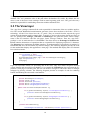
Figure 24: Registration form
Figure 24 shows the final form which was produced with the above presented code. The form shows
also some example data transferred from the database (see further description).
Forms can also present the data, which was passed by the Presenter from the Model. An example is
shown in code below which is a fragment of the VPromotionDetailsPage class. The initial code was
generated by ReDSeeDS just as shown previously. To present data, we need to pass an appropriate
21
DTO. This necessitates certain manual changes. The first step is to add a parameter to the default constructor.
public class VPromotionDetailsPage extends ContentPane implements ActionListener {
...
private XPromotionData promotion;
public VPromotionDetailsPage(XPromotionData p){
this.promotion = p;
}
}
We also need to remember to change the IView interface and the EchoApp class. Next, we need to
write code to transfer data from theXPromotionData DTO to the form’s fields. We also need to block
edition capabilities of the respective text fields. The code pertaining to “promotion name” is shown
below (see the highlighted lines).
//Add control for notion attribute
promotionNameLabel = new Label("promotion name: ");
gridLayout = new GridLayoutData();
gridLayout.setAlignment(Alignment.ALIGN_RIGHT);
promotionNameLabel.setLayoutData(gridLayout);
grid.add(promotionNameLabel);
promotionNameTextField = new TextField();
promotionNameTextField.setText(promotion.getPromotionName());
promotionNameTextField.setEnabled(false);
promotionNameTextField.setWidth(new Extent(75, Extent.PERCENT));
grid.add(promotionNameTextField);
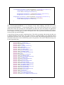
After running the application, the screen looks as in Figure 25.
Figure 25: Promotion details screen
The last element from the View layer that we will discuss is the message window. They can be used to
communicate short texts. Classes that implement such windows extend the WindowPane class. These
elements don’t need any specific improvements from the programmer. However, a proper message
should be specified in the appropriate source RSL element.
public class VCancelReservationConfirmationMessage extends WindowPane implements
ActionListener {
private
private
private
private
private
Button _okButton;
MutableStyle buttonStyle;
Column column;
Label messageText;
IPresenter presenter;
22
public VCancelReservationConfirmationMessage(){
}
...
public void init(IPresenter presenter){
...
// Add message content
setTitle("Message");
setModal(true);
messageText = new Label("Reservation has been cancelled successfully.");
column.add(messageText);
...
}
The above code presents a fragment of the VCancelReservationConfirmationMessage class, which
informs the user about successful cancellation of a reservation. The structure of this class is very simple. It contains the “messageText” field one button (“_okButton”). The presented fragment of the init()
method is responsible for placing the title and the message inside the window. The result of this code
is presented in Figure 26.
Figure 26: Okno komunikatu o pomyślnym anulowaniu rezerwacji
The last fragment is to handle the button event. As it can be noticed, after clicking “OK”, the window
should be closed and usually the previous window should be shown. This necessitates an update to the
generated code, as shown below (see the highlighted line).
public void actionPerformed(ActionEvent e){
if (e.getActionCommand().equals("_okButton")) {
userClose();
((EchoApp) ApplicationInstance.getActive()).closeCurrentPage();
}
}
The default constructor of the message window has no parameters and in most cases this is satisfactory. In some situations we need to show some more information to the user. An example is the following code where an additional parameter (reservation number) is passed and displayed.
public class VConfirmationToEnrollForFitnessClassesMessage extends WindowPane implements ActionListener {
private
private
private
private
Button _okButton;
MutableStyle buttonStyle;
Column column;
Label messageText;
23
private IPresenter presenter;
private int reservationID;
public VConfirmationToEnrollForFitnessClassesMessage( int id){
this.reservationID = id;
}
}
After these manual changes, the window looks in Figure 27.
Figure 27: Okno komunikatu o pomyślnym zapisaniu się na zajęcia fitness
3.4 The Presenter layer
The Presenter manages the whole application. It is an intermediary in communication between the
Model and the View. It controls the behavior according to the use case scenarios. The contents of the
main “App.Presenter” package is shown in Figure 28.
Figure 28: Zawartość pakietu ‘App.Presenter’
It consists of two elements. IPresenter is the interface that defines all the application logic operations.
It is implemented by the PresenterImpl class.
public interface IPresenter {
public void SelectsAddFitnessClassesButton();
public void SelectsAddNewFitnessClassesButton();
public void SelectsAddPromotionButton();
public void SelectsAddTrainerButton();
public void SelectsAddTrainingButton();
public void SelectsCancelReservationButton();
24
public void SelectsChangeButton();
public void SelectsChangePasswordButton();
public void SelectsChangePersonalDataButton();
public void SelectsCreateAccountButton();
…
}
The above code show part of the IPresenter definition directly after its generation. All the methods
represent actions performed after a UI event (pressing buttons).
public class PresenterImpl implements IPresenter {
private IModel model;
int res;
private IView view;
public PresenterImpl(){
}
...
public void SelectsAddFitnessClassesButton(){
res = model.ValidatesFitnessClassesData();
if ( res == 1 /*fitness classes data valid*/) {
res = model.SavesFitnessClassesData();
view.showNewFitnessClassesConfirmationMessage();
} else if ( res == 2 /*day or time invalid*/) {
view.showNewFitnessClassesError();
}else if( res == 3 /*incorrect or missing data*/) {
view.showGeneralValidationError();
}
}
...
}
The above fragment is generated automatically. The SelectAddFitnessClassesButton() method is called
while processing the “Add fitness classes” use case. This is done after the manager fills-in the form
and presses the appropriate button. The first step is to call the validation method from the Model.
Next, based on the results of this validation, one of alternative actions is taken. If the data is correct, it
is saved and then confirmation message is displayed. In other cases, an error message is displayed.
This logic reflects exactly the logic expressed in respective use case scenarios.
It can be noted that the IPresenter operations have not parameters. Thus, a key modification is to add
appropriate DTO parameters. This is explained using the “Create profile” use case. When the user data
is entered, it has to be transferred to the Presenter. The following code presents the appropriate method
updated with the parameters.
public void SelectsCreateAccountButton(XPersonalData rd, XCredential c){
res = model.ValidatesRegistrationData(c);
if ( res == 1 /*registration data is valid*/) {
res = model.SavesPersonalData(rd, c);
view.showRegisterConfirmationMessage();
} else if ( res == 2 /*registration data is not valid*/) {
view.showRegistrationError();
}
}
The two paratmers are of types: XPersonalData oraz XCredential, which were generated automatically. The data is transferred from the View to the Model using DTOs of these two types. It is worth
noting that the methods in the View layer have necessary parameters generated and also the related
25
procedure calls in the Presenter have these parameters present. This is illustrated in the following
code.
public void SelectsSwimmingPoolScheduleButton(){
List<XSwimmingPoolScheduleItemData> swimmingPoolSchedule = null;
swimmingPoolSchedule = model.DownloadsSwimmingPoolSchedule();
view.showSwimmingPoolSchedulePage(swimmingPoolSchedule);
}
3.5 The Model layer
The Model layer contains all the data processing and data storage operations. Just like for the Presenter, the structurte of the Model is very simple. This is illustrated in Figure 29.
Figure 29: Zawartość pakietu „App.Model"
The IModel interface declares all the data processing operations, and the ModelImpl class implements it.
public interface IModel {
public int ChangesCredentials();
...
public int DeletesTrainerData();
public int DeletesTrainingData();
...
public int DownloadsPersonalData();
public int DownloadsPromotionsList();
...
public int SavesTrainingData();
public int ValidatesCredentials();
...
}
The above fragment shows some of the operations of the IModel interface for our example system.
The related methods consist in validating, reading, modifying and saving objects and lists of objects.
They are also generated without any parameters. ReDSeeDS does not generate any code of the Model
methods. This is entirely left to the programmer. However, for vast majority of the methods this task is
quite simple. It is mostly equivalent to calling appropriate methods from the “App.DAO” package,
already presented previously in this guide. All the generated operations return an integer value which
26
might be used for passing some result statuses of the operations. The code fragment below illustrates
how one of the methods was manually updated with necessary code.
public List<XTrainingData> DownloadsTrainingsList(){
ConnectionFactory f = new ConnectionFactory();
Connection connection = f.getConnection();
TrainingDataDAO s_dao = new TrainingDataDAO(connection);
List<XTrainingData> trainings = new ArrayList<XTrainingData>();
trainings = s_dao.getTrainings();
return trainings;
}
This method serves retrieving lists of available excercises from the database. It creates and initiates
two objects of types ConnectionFactory and Connection. Then, it initiates a TrainingDataDAO
object. To retrieve the list, the previously defined getTrainings() method is used. Another example
presents the method to save the new promotion data.
public int SavesPromotionData(XPromotionData p){
ConnectionFactory f = new ConnectionFactory();
Connection connection = f.getConnection();
PromotionDataDAO p_dao = new PromotionDataDAO(connection);
int res = p_dao.savePromotion(p);
return res;
}
In this case, an input parameter (XPromotionData) had to be added. This schema can be used to implement all other methods in the Model layer.
27