1
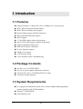
IEEE802.11a+g Access Point with PoE
User’s Guide
Version 1.0
Aug. 2005
Copyright Statement
No part of this publication may be reproduced, stored in a retrieval system, or
transmitted in any form or by any means, whether electronic, mechanical,
photocopying, recording or otherwise without the prior writing of the publisher.
Windows® 98/ME/2000/XP are trademarks of Microsoft® Corp.
All copyright reserved.
1
Table of Contents
1. INTRODUCTION
5
1.1 FEATURES
1.2 PACKAGE CONTENTS
1.3 SYSTEM REQUIREMENTS
1.4 WIRELESS NETWORK SCENARIOS
AS AN ACCESS POINT
AS A STAND-ALONE REPEATER
AS A POINT TO MULTI-POINTS BRIDGE
5
5
5
6
6
7
7
2. HARDWARE INSTALLATION
8
2.1 APPEARANCE
2.2 HARDWARE CONNECTION
8
9
3. ETHERNET / WLAN CLIENT
10
4. ACCESS WEB-BASED UTILITY
12
5. SETUP WIZARD
13
5.1 TIME SETTINGS
5.2 DEVICE IP SETTINGS
5.3 WIRELESS SETTINGS
5.3.1 SECURITY-WEP
5.3.2 802.1X
5.3.3 WPA-PSK / WPA2-PSK
5.3.4 WPA / WPA2
13
14
15
17
18
19
20
5.4 SAVE CONFIG
21
6. ADVANCED SETTINGS
22
6.1 PASSWORD SETTINGS
6.2 SYSTEM MANAGEMENT
6.3 SNMP SETTINGS
6.4 MAC FILTERING SETTINGS
22
23
25
27
2
6.5 WIRELESS SETTINGS
6.6 OPERATIONAL MODE
6.7 RADIUS SETTINGS
28
30
31
7. DEVICE STATUS
33
7.1 SYSTEM LOG
7.2 WIRELESS CLIENT TABLE
7.3 BRIDGE TABLE
34
35
35
8. SYSTEM TOOLS
36
8.1 FIRMWARE UPGRADE
8.2 CONFIGURATION SAVE OR RESTORE
8.3 FACTORY DEFAULT
8.4 REBOOT
9 HELP
36
37
38
38
39
9.1 WHAT IF YOU FORGOT THE PASSWORD?
10. SPECIFICATION
39
40
3
Regulatory Information
Federal Communication Commission Interference Statement
This equipment has been tested and found to comply with the limits for a Class B digital
device, pursuant to Part 15 of the FCC Rules. These limits are designed to provide reasonable
protection against harmful interference in a residential installation. This equipment generates,
uses and can radiate radio frequency energy and, if not installed and used in accordance with
the instructions, may cause harmful interference to radio communications. However, there is
no guarantee that interference will not occur in a particular installation. If this equipment does
cause harmful interference to radio or television reception, which can be determined by
turning the equipment off and on, the user is encouraged to try to correct the interference by
one of the following measures:
- Reorient or relocate the receiving antenna.
- Increase the separation between the equipment and receiver.
- Connect the equipment into an outlet on a circuit different from that to which
the receiver is connected.
- Consult the dealer or an experienced radio/TV technician for help.
FCC Caution: To assure continued compliance, (example - use only shielded interface cables
when connecting to computer or peripheral devices) any changes or modifications not
expressly approved by the party responsible for compliance could void the user’s authority to
operate this equipment.
This device complies with Part 15 of the FCC Rules. Operation is subject to the following two
conditions: (1) This device may not cause harmful interference, and (2) this device must
accept any interference received, including interference that may cause undesired operation.
IMPORTANT NOTE:
FCC Radiation Exposure Statement:
This equipment complies with FCC radiation exposure limits set forth for an
uncontrolled environment. This equipment should be installed and operated
with minimum distance 20cm between the radiator & your body.
This transmitter must not be co-located or operating in conjunction with any other
antenna or transmitter.
4
1. Introduction
1.1 Features
High performance 11 Mbps (802.11b) or 54Mbps (802.11a/g) data rate
Wi-Fi, WPA certificated interoperability
WDS (Wireless Bridge) mode support
Repeater Mode support (Wireless Repeater)
WPA with PSK/TKIP/AES support
WPA2 support
152-bit WEP support (Atheros Proprietary)
Super A/G™ mode support (Atheros Proprietary)
Support adjustable output power
IEEE 802.3af (PoE) compliance
Privacy Separator support
SNMP v1/v2 support
ACKTimeOut setting
User Limitation (Static Load Balancing)
1.2 Package Contents
One 802.11A+G ACCESS POINT
One 5V AC power adapter with a barrel connector
CD of the 802.11A+G ACCESS POINT User’ Guide
Two Reverse SMA Antennas
1.3 System Requirements
PC (equipped with Ethernet network card or wireless adapter and has appropriate
network card driver and TCP/IP installed)
Windows® 98/SE/2000/XP
RJ-45 Ethernet Cable
5
1.4 Wireless Network Scenarios
A group of wireless stations communicating with each other is called a Basic
Service Set (BSS) and is identified by a unique SSID.
When an 802.11A+G ACCESS POINT is used, it can be configured to operate in the
following three network configurations
As An Access Point
When configured in the Access Point mode, the 802.11A+G ACCESS POINT
allows a group of wireless stations to communicate with each other through it. Such
a network is called an Infrastructure BSS.
The 802.11A+G ACCESS POINT further provides bridging functions between the
wireless network and the wired LAN network.
When multiple access points are connected to the same LAN segment, stations can
roam from one 802.11A+G ACCESS POINT to another without losing their
connections, as long as they are using the same SSID. This is shown in the
diagram below.
6
As A Stand-Alone Repeater
The purpose of a repeater is to expand an existing infrastructure BSS. When
configured to operate in the Repeater Mode, the 802.11A+G ACCESS POINTs sit
between wireless stations and a “root” AP whose BSS is being expanded, as shown
below:
As A Point to Multi-Points Bridge
When configured to operate in the Wireless Distribution System (WDS) Mode, the
802.11A+G ACCESS POINT provides bridging functions between the LAN behind
it and separate LANs behind other AP’s operating in the WDS mode. The system
will support up to eight such AP’s in a WDS configuration.
Note that an 802.11A+G ACCESS POINT running in the WDS mode can also
support wireless stations simultaneously, as shown in the left most AP in the
diagram below:
7
2. Hardware Installation
2.1 Appearance
ANTENNA
POWER
RESET
LAN
POWER:
RESET:
Power connector.
Resets the AP to factory defaults. Insert a straightened paperclip
into the hole to press the button. Press and hold for about 2~5
seconds, and then wait for the AP to finish booting.
LAN:
Lan cable connector.
LED Description
11a
11b/g
100M
LINK/ACT
Power
Status
On
OFF
Blinking
Wireless
Link is activated
No Wireless connection
Transmit / Receive Data
LAN
Link is activated
No LAN connection
Transmit / Receive Data
8
Power
Power
No Power
2.2 Hardware Connection
1
Choose a place for the AP.
(1) Locate the AP at the center of your wireless network for better coverage
of the wireless stations.
(2) Adjust the direction of the antennas.
2
Connect the cables.
(1) Connect the power cable.
(2) Connect one end of the Ethernet cable to the AP and the other end to the
PC.
LAN
POWER
Electrical Outlet
PC
9
3. Ethernet / WLAN Client
You can access the AP’s Web interface via Ethernet or wireless network. Before
doing so, you have to make sure that your PC is on the same subnet with the AP.
The AP’s default settings are:
IP Address: 192.168.1.1
Subnet Mask: 255.255.255.0
DHCP server: Disabled
Therefore, you need a static IP for your PC’s TCP/IP settings:
IP Address: 192.168.1.* (* is a number between 2~254)
Subnet Mask: 255.255.255.0
Follow the steps below to configure a static IP for your PC. Later, if you enable the
AP’s DHCP server, you may set your PC to be a DHCP client.
1
Set up TCP/IP for your PC.
For Windows 98/ME
(1) Click Start→Settings→Control Panel.
(2)
(3)
(4)
(5)
(6)
(7)
Double click “Network”.
Select “TCP/IP” protocol and click “Properties”.
On the IP Address tab, select “Specify an IP address”.
Enter the IP address and subnet mask.
Select Gateway tab and set the gateway value.
Click “OK” twice to save the new settings. Restart your PC if necessary.
For Windows 2000/XP
(1) Click Start→Settings→Control Panel.
(2) Double click “Network Dial-up Connections” or “Network
Connections”.
(3) Right click “Local Area Connection” and select “Properties”.
(4) Select “Use the following IP address” and enter the IP settings.
(5) Click “OK” when finished.
2
Set up wireless client.
If you choose to wirelessly access the AP, be sure your PC is equipped with
802.11a or 802.11b or 802.11g wireless devices. If you found that your
wireless device cannot communicate with the AP, even the link status
10
indicates a successful connection, make sure the following settings are
properly configured.
Operation Mode: Infrastructure
SSID: wlan
Authentication: Open
Encryption: None
11
4. Access Web-Based Utility
1
Be sure the AP is installed and PC is configured properly.
Make sure you have followed steps described in Chapter 2 and Chapter 3 for
Hardware Installation and PC Configuration.
2
Open the Web browser and type http://192.168.1.1 in URL field.
This address is the default IP of the AP.
3
Utility window appears. Click “Setup Wizard”.
4
Log-on page appears. Enter “password”, and click “LOG ON”.
The default password is “password”. The password you entered is displayed
as a string of dots.
5
See Chapter 5~Chapter 9 for using the Configuration Utility.
You may click “Help” to get help with commonly asked questions about the
AP.
12
5. Setup Wizard
The Setup Wizard will guide you through a series of configuration screens to set up
the basic functionality of the device. After you finish the settings, remember to press
the “FINISH” button for the settings to take effect. See Chapter 5.4 Save Config for
details.
5.1 Time Settings
After logging in, the time settings page appears. The device time is automatically
set to the local time of the management PC at the first time a connection is made. To
modify the device’s time, modify the appropriate fields, then click NEXT.
13
5.2 Device IP Settings
The Device IP Settings screen allows you to configure the IP address and subnet of
the device. Although you can rely on a DHCP server to assign an IP address to the
802.11A+G ACCESS POINT automatically, it is recommended that you configure a
static IP address manually in most applications.
If you choose to assign the IP address manually, check the button that says “Assign
static IP to this device” and then fill in the following fields
IP Address and IP Subnet Mask: These values default to 192.168.1.1 and
255.255.255.0, respectively. It is important to note that there are similar
addresses falling in the standard private IP address range and it is an essential
security feature of the device. Because of this private IP address, the device can
no longer be accessed (seen) from the Internet.
Gateway IP Address: Enter the IP address of your default gateway.
DNS Server: The Domain Name System (DNS) is a server on the Internet that
translates logical names such as “www.yahoo.com” to IP addresses like
66.218.71.80. In order to do this, a query is made by the requesting device to a
DNS server to provide the necessary information. If your system administrator
requires you to manually enter the DNS Server addresses, you should enter
them here.
14
If you choose to use a DHCP Server to acquire an IP address for the 802.11A+G
Access Point automatically, check the button that says, “Use the DHCP protocol to
automatically get the IP address for this device”. Again, as a reminder, it is
recommended that your 802.11A+G ACCESS POINT should be assigned a static IP
address in order to make it easy for you to manage the device later on.
5.3 Wireless Settings
Network Name (SSID): The SSID is the network name used to identify a
wireless network. The SSID must be the same for all devices in the wireless
network (i.e. in the same BSS). Several access points on a network can have the
same SSID. The SSID length is up to 32 characters. The default SSID is
“wlan”.
Disable SSID Broadcasting: An access point periodically broadcasts its SSID
along with other information, which allows client stations to learn its existence
while searching for access points in a wireless network. Check Disable if you
do not want the device to broadcast the SSID.
15
The wireless module is IEEE 802.11g and 802.11b
compliant, and choosing “11g/b” allows both 802.11b and 802.11g client
stations to get associated. However, choosing “11g” allows only 802.11g client
stations to get associated and get better overall performance. 802.11a is not
Mode (WLAN Mode):
compliant with either 802.11b or 802.11g; choosing “11a” only allows 802.11a
client stations to get associated. The same explanation for both of the radios.
Channel: Select a channel from the available list to use. All devices in a BSS
must use the same channel. You can select Auto to let the system pick up the
best channel for you.
Note! The available channels are different from country to country and for
different WLAN mode.
Security Policy: You can select different security policy to provide association
authentication and/or data encryption. See Chapter 5.3.1~Chapter 5.3.4 for
details.
16
5 . 3 . 1 S e c u r i t y- W E P
WEP allows you to use data encryption to secure your data from being eavesdropped
by malicious people. It allows 3 types of key: 64 (WEP64), 128 (WEP128), and
152 (WEP152) bits. You can configure up to 4 keys using either ASCII or
Hexadecimal format.
Key Settings (WEP Key 1~4): The length of a WEP64 key must be equal to 5
bytes, a WEP128 key is 13 bytes, and a WEP152 key is 16 bytes. For WEP64
and WEP128, you can just enter a pass-phrase and click the GENERATE
button to generate the four keys. So you can use a mnemonic string as the
pass-phrase instead of memorizing the four keys.
Key Index: You have to specify which of the four keys will be active.
Once you enable the WEP function, please make sure that both the 802.11A+G
ACCESS POINT and the wireless client stations use the same key.
Note! Some wireless client cards only allow Hexadecimal digits for WEP keys.
Please note that when configuring WEP keys, a WEP128 ASCII key
looks like “This is a key”(13 characters), while a WEP128 Hex key looks
like “54-68-69-73-20-69-73-20-61-20-6b-65-79”(13 bytes).
17
5.3.2 802.1x
802.1x allows users to leverage a RADIUS server to do association authentications.
You can also enable dynamic WEP keys (64, 128, 152-bit) to have data encryption.
Here you do not have to enter the WEP key manually because it will be generated
automatically and dynamically.
Note! After you have finished the configuration wizard, you have to configure the
Radius Settings in Advanced Settings in order to make the 802.1x function
work.
18
5.3.3 WPA-PSK / WPA2-PSK
Wi-Fi Protected Access (WPA) with Pre-Shared Key (PSK) provides better security
than WEP keys. It does not require a RADIUS server in order to provide association
authentication, but you do have to enter a shared key for the authentication purpose.
The encryption key is generated automatically and dynamically.
Pre-shared Key: This is an ASCII string with 8 to 63 characters. Please make
sure that both the 802.11A+G ACCESS POINT and the wireless client stations
use the same key.
Encryption Type: There are two encryption types TKIP and CCMP (AES).
While CCMP provides better security than TKIP, some wireless client stations
may not be equipped with the hardware to support it. You can select Both to
allow TKIP clients and CCMP clients to connect to the Access Point at the
same time.
Group Rekey Interval: A group key is used for multicast/broadcast data, and
the rekey interval is time period that the system will change the group key
periodically. The shorter the interval is, the better the security is. 60 seconds is
a reasonable time, and it is used by default.
19
5.3.4 WPA / WPA2
Wi-Fi Protected Access (WPA) requires a RADIUS server available in order to do
authentication (same as 802.1x), thus there is no shared key required.
The Encryption Type and Group Rekey Interval settings are same as WPA-PSK’s.
20
5.4 Save Config
If you make changes on the web-based configuration utility, remember to press the
FINISH button for your modification to take effect. This also makes your new
settings saved into the permanent memory on your system.
Congratulations! You are now ready to use the 802.11A+G ACCESS POINT.
Note! If you change the device’s IP address, as soon as you click on FINISH
you will no longer be able to communicate with your 802.11A+G
ACCESS POINT. You need to change your IP address and then re-boot
your computer in order to resume the communication.
21
6. Advanced Settings
The Advanced Settings tab on the top row of the window allows you to perform
modifications that normally you may not need to do for general operations except
changing your password from the default factory setting (this is highly recommended
for security purposes).
6.1 Password Settings
The default factory password is “password”. To change the password, press the Password
Settings button to enter the Password Settings screen, then enter the current password
followed by the new password twice. The entered characters will appear as asterisks.
22
6.2 System Management
Clicking the System Management button to configure system related parameters to
for the 802.11A+G ACCESS POINT.
Local Management: Choose whether to disable the management from wireless
client or not.
Management Session Time-out: This setting specifies the duration of idle
time (inactivity) before a web browser or telnet management session times out.
The default time-out value is 10 minutes.
UPnP: The Universal Plug and Play (UPnP) feature allows a Windows
XP/ME PC to discover this 802.11A+G Access Point and automatically show
an icon on the screen. Then a user can double-click the icon to access this
23
device directly (without having to find out its IP address).
Syslog: Syslog is an IETF (Internet Engineering Task Force - the Internet
standards body)-conformant standard for logging system events (RFC-3164).
When the 802.11A+G ACCESS POINT encounters an error or warning
condition (e.g., a log-in attempt with an invalid password), it will create a log in
the system log table. To be able to remotely view such system log events, you
need to check the Enable Syslog box and configure the IP address of a Syslog
daemon. When doing so, the 802.11A+G ACCESS POINT will send logged
events over network to the daemon for future reviewing.
Syslog server IP address: The IP address of the PC where the Syslog daemon
is running.
Email Log: Choose whether or not to enable Email Log. If enabled, enter the
email server and email address.
24
6.3 SNMP Settings
Click SNMP Settings to configure SNMP Community. SNMP (Simple Network
Management Protocol) is a widely used network monitoring and control protocol.
SNMP works by sending messages, Protocol Data Units (PDUs), to different parts of
a network. SNMP-compliant devices, called agents, store data about themselves in
Management Information Bases (MIBs) and return this data to the SNMP requests.
Enable SNMP: Choose whether or not to enable SNMP.
System Information: Enter the Name, Location and Contact persons for
SNMP manager.
Community String: Access to the SNMP device is controlled through
community strings. Community strings can be thought of as passwords.
If
you don’t have the correct community strings, you cannot retrieve any data or
25
make any changes.
or for Write.
Community strings can control the access rights: for Read
Name and IP Address:
Enter Name and IP Address for SNMP trap manager.
SNMP Trap: The Access point receives SNMP Traps from network
equipment (routers, switches and workstations). Traps are sent when errors or
specific events occur on the network. Traps are normally only sent to end
stations which are currently sending SNMP requests to the device in question.
26
6.4 MAC Filtering Settings
The 802.11A+G ACCESS POINT allows you to define a list of MAC addresses that
are allowed or denied to access the wireless network
To add a MAC address into the table, enter a mnemonic name and the MAC address,
and then click ADD.
The table lists all configured MAC Filter entries. To delete entries, check the
corresponding select boxes and then press DELETE SELECTED.
Disable MAC address control list: When selected, no MAC address filtering
will be performed.
Enable GRANT address control list: When selected, data traffic from only
the specified devices in the table will be allowed in the network.
Enable DENY address control list: When selected, data traffic from the
devices specified in the table will be denied/discarded by the network.
27
6.5 Wireless Settings
Beacon Interval: The 802.11A+G ACCESS POINT broadcasts beacon frames
regularly to announce its existence. The beacon Interval specifies how often
beacon frames are transmitted - in time unit of milliseconds. The default value
is 100, and a valid value should be between 1 and 65,535.
RTS Threshold: RTS/CTS frames are used to gain control of the medium for
transmission. Any unicast (data or control) frames larger than specified RTS
threshold must be transmitted following the RTS/CTS handshake exchange
mechanism. The RTS threshold should have a value between 1-2347 bytes,
with a default of 2347. It is recommended that this value does not deviate from
the default too much.
28
Fragmentation Threshold: When the size of a unicast frame exceeds the
fragmentation threshold, it will be fragmented before the transmission. It
should have a value of 256-2346 bytes, with a default of 2346. If you
experience a high packet error rate, you should slightly decrease the
Fragmentation Threshold.
DTIM Interval: The 802.11A+G ACCESS POINT buffers packets for stations
that operate in the power-saving mode. The Delivery Traffic Indication
Message (DTIM) informs such power-conserving stations that there are packets
waiting to be received by them. The DTIM interval specifies how often the
beacon frame should contain DTIMs. It should have a value between 1 to 255
with a default value of 3.
Enable privacy separator for 2 radio: enable/disable.
Radio 1/Radio 2 Transmit Power: 100%, 75%, 50%, 25%, 12%.
Age Out Timer: Ranges from 10 to 65535 seconds. The default is 300.
AckTimeOut: Ranges from 10 to 255. The default is 25.
AckTimeOut (Turbo-11a): Ranges from 10 to 255. The default is 22.
AckTimeOut(11g): Ranges from 10 to 255. The default is 48.
AckTimeOut(Turbo-11g): Ranges from 10 to 255. The default is 22.
29
6.6 Operational Mode
The 802.11A+G ACCESS POINT can be configured to operate in one of the
following two modes as mentioned previously in Chapter 1.4 Wireless Network
Scenarios:
(1) Access Point
(2) Wireless Distribution System (Bridge Mode)
When configured as a Bridge, you need to further configure the name and MAC
address of its peer Wireless Distribution System devices.
30
6.7 Radius Settings
Radius servers provide centralized authentication services to wireless clients.
Two user authentication methods can be enabled: one based on MAC address filter,
the other based on 802.1x EAP authentication.
MAC address filtering based authentication requires a MAC address filter table to be
created in either the 802.11A+G ACCESS POINT (as described in the Chapter 6.4
MAC Filtering Settings) and/or the Radius server. During the authentication phase
of a wireless station, the MAC address filter table is searched for a match against the
wireless client’s MAC address to determine whether the station is to be allowed or
denied to access the network.
The Radius server can also be used for 802.1x EAP authentication. IEEE 802.1x is
an IEEE standard that is based on a framework that involves stations to be
authenticated (called Supplicant), an authentication server (a Radius Server) that
provides authentication services, and an authenticator that provides necessary
translation and mediating functions between the authentication server and the
stations to be authenticated. The 802.11A+G ACCESS POINT acts as an
authenticator, and it relays authentication messages between the RADIUS server and
client devices being authenticated.
IEEE 802.1x EAP authentication is enabled by selecting the Security Policy as
802.1x or WPA (see Chapter 5.3 Wireless Settings).
31
Enable Radius Server: Check this option to enable RADIUS server.
Server IP: The IP address of the RADIUS server
Port Number: The port number that your RADIUS server uses for
authentication. The default setting is 1812.
Shared secret: This is used by your RADIUS server in the Shared Secret field
in Radius protocol messages. The shared secret configured in the 802.11A+G
ACCESS POINT must match the shared secret configured in the RADIUS
server. The shared secret can contain up to 64 alphanumeric characters.
Retry Times: The number of times the 802.11A+G ACCESS POINT should
attempt to contact the primary server before giving up.
32
7. Device Status
The following chapters cover other management aspects of your 802.11A+G
ACCESS POINT:
How to view the device status
How to view the system log
How to upgrade the firmware of your 802.11A+G ACCESS POINT
How to save or restore configuration changes
How to reset the configuration to the factory default.
How to reboot your 802.11A+G ACCESS POINT
What if you forgot the password
You can monitor the system status and get general device information from the
Device Information screen:
This is at the left-bottom corner of the Device Status
window.
33
7.1 System Log
The 802.11A+G ACCESS POINT maintains a system log that you can use to track
events that have occurred in the system. Such event messages can sometimes be
helpful in determining the cause of a problem that you may have encountered.
You can select System Log on the left side of the Device Status window to view log
events recorded in the system. The System Log entries are shown in the main screen
along with the log level, the severity level of messages that are being displayed
(lower is severer), and the uptime, which is the amount of time since the 802.11A+G
ACCESS POINT was boot-up.
34
7.2 Wireless Client Table
The wireless client table lists the current wireless clients and its MAC address, state,
and traffic statistics. You can check this table by clicking Wireless Client Table at
the left side of the Device Status window.
7.3 Bridge Table
The bridge table shows all MAC entries learned from the wired LAN interface,
wireless clients, and WDS peers (if running in the WDS mode). You can check this
table by clicking Bridge Table at the left side of the Device Status window.
35
8. System Tools
8.1 Firmware Upgrade
You can upgrade the firmware of your 802.11A+G ACCESS POINT (the software
that controls your 802.11A+G ACCESS POINT’s operation). Normally, this is done
when a new version of firmware offers new features that you want, or solves
problems that you have encountered with the current version. System upgrade can
be performed through the System Upgrade window as follows:
1
In System Tools tab, select “Firmware Upgrade”.
Browse
2
Download the firmware.
Download the firmware from the distributor’s web site to your local disk.
3
Enter the path and filename and then click “UPGRADE”.
Enter the path and filename of the downloaded firmware file (or click
Browse to locate the firmware file). Click the Upgrade button to start
upgrading.
36
4
Reset the system.
When the upgrading is complete, you need to reset the system for the new
firmware to take effect.
Note!
It is recommended that you do not upgrade your 802.11A+G ACCESS
POINT unless the new firmware contains a new feature that you want
or if it contains a fix to a problem that you’ve encountered.
8.2 Configuration Save or Restore
You can save system configuration settings to a file, and later download it back to
the 802.11A+G ACCESS POINT by following the steps below.
1
In System Tools tab, select “Configuration Save and Restore”.
Browse
2
Click “SAVE TO FILE” or “RESTORE FROM FILE”.
Click “SAVE TO FILE” to save your configuration to a management host.
To restore from file, please enter the path of the configuration file (or click
the Browse button to locate the file) and then click “RESTORE FROM
FILE”.
37
8.3 Factory Default
You can reset the configuration of your 802.11A+G ACCESS POINT to the factory
default settings.
1
In System Tools tab, select “Factory Default”.
2
Click YES button.
8.4 Reboot
You can reboot your 802.11A+G ACCESS POINT from the Browser.
1
In System Tools tab, select “Reboot System”.
2
Click YES button.
Note!
Rebooting the 802.11A+G ACCESS POINT disconnects any active
clients, and therefore will disrupt any current data traffic.
38
9 Help
You can click “Help” to get help with frequently asked questions about the wireless
Access Point.
9.1 What If You Forgot the Password?
If you forgot the password, the only way to recover is to clear the device
configuration and return the unit to its original state as shipped from the factory. To
do so, insert a straightened paperclip into the RESET hole on the back panel of the
AP to press the button. Press and hold for about 2~5 seconds, and then wait for the
AP to finish booting. Please note that this will also clear your current configuration
and restore the configuration from the factory default.
39
10. Specification
Dimension
190.0(L) x 145.5(w) x 29.0(H) mm
LAN Port
1X RJ-45 10/100Mbps port with PoE (802.3af) support
Power Supply
External Power Adapter with 100V,input 5V/2A
Power Over Ethernet (802.3afl)
Operating
0 ~ 40°C
Temperature Range
Operating Humidity 10% to 90%
Range
IEEE802.11a 5GHz OFDM
Wireless LAN
IEEE802.11b 2.4GHz CCK
Standard
IEEE802.11g 2.4GHz OFDM
Compliance
Atheros Proprietary Super A/G™ mode
Wireless
Frequency Range
802.11a:
4.9 to 5.0 and 5.03 to 5.091GHz
5.15 to 5.25 GHz
5.15 to 5.35 GHz
5.725 to 5.825 GHz
802.11b/g:
2.412~2.472GHz
2.412~2.462GHz
Channels Support
(Default: Japan)
802.11b only
FCC: 11 (1~11)
Europe(ETSI): 13 (1~13)
Japan: 14 (1~14)
802.11b/g
FCC: 11 (1~11)
Europe(ETSI): 13 (1~13)
Japan: 13 (1~13)
802.11a
FCC: 12
Europe(ETSI): 19
Japan: 4 (34,38,42,46)
802.11a Turbo
FCC: 5
Atheros Proprietary Super A/G™ mode
40
Super a without Turbo (Japan)
Super a with Dynamic Turbo
Super a with Static Turbo
802.11g Turbo
Super g without Turbo (Japan)
Super g with Dynamic Turbo
Super g with Static Turbo
Modulation
Technology
Wireless Transmit
Power
Orthogonal Frequency Division Multiplexing (OFDM)
Complementary Code Keying (CCK)
IEEE802.11a mode: 17dBm@54Mbps
20dBm@6Mbps
IEEE802.11g mode: 17dBm@54Mbps
20dBm@11Mbps
20dBm@1Mbps
IEEE802.11b mode: 14dBm
Wireless Receive
Sensitivity
IEEE802.11a mode: -85dBm@6Mbps
-65dBm@54Mbps
IEEE802.11g mode: -91dBm@1Mbps
-84dBm@11Mbps
-65dBm@54Mbps
WLAN Network
Architecture Type
Infrastructure mode
WDS
Repeater
Wireless Operation Indoor: Up to 50 m
Range
Outdoor: Up to 300m
Compliant
Radio Approvals: pass TELEC/FCC pre-test
Standards
EMI and Susceptibility (Class B): Pass VCCI/FCC pre-test
Others:
IEEE 802.11a
IEEE 802.11g
IEEE 802.3af
41